EP1243682A2 - Method and apparatus for longitudinal orientation of hosiery articles - Google Patents
Method and apparatus for longitudinal orientation of hosiery articles Download PDFInfo
- Publication number
- EP1243682A2 EP1243682A2 EP02006372A EP02006372A EP1243682A2 EP 1243682 A2 EP1243682 A2 EP 1243682A2 EP 02006372 A EP02006372 A EP 02006372A EP 02006372 A EP02006372 A EP 02006372A EP 1243682 A2 EP1243682 A2 EP 1243682A2
- Authority
- EP
- European Patent Office
- Prior art keywords
- sock
- duct
- sensors
- dragging
- orientation
- Prior art date
- Legal status (The legal status is an assumption and is not a legal conclusion. Google has not performed a legal analysis and makes no representation as to the accuracy of the status listed.)
- Withdrawn
Links
- 238000000034 method Methods 0.000 title claims abstract description 20
- 210000003127 knee Anatomy 0.000 claims abstract description 5
- 238000011144 upstream manufacturing Methods 0.000 claims description 6
- 238000001514 detection method Methods 0.000 claims description 4
- 230000003287 optical effect Effects 0.000 claims description 3
- 230000000903 blocking effect Effects 0.000 claims description 2
- 238000010025 steaming Methods 0.000 description 3
- 238000010586 diagram Methods 0.000 description 2
- 238000004519 manufacturing process Methods 0.000 description 2
- 238000004806 packaging method and process Methods 0.000 description 2
- 230000006978 adaptation Effects 0.000 description 1
- 238000003491 array Methods 0.000 description 1
- 238000012986 modification Methods 0.000 description 1
- 230000004048 modification Effects 0.000 description 1
- 238000004826 seaming Methods 0.000 description 1
Images


Classifications
-
- D—TEXTILES; PAPER
- D06—TREATMENT OF TEXTILES OR THE LIKE; LAUNDERING; FLEXIBLE MATERIALS NOT OTHERWISE PROVIDED FOR
- D06C—FINISHING, DRESSING, TENTERING OR STRETCHING TEXTILE FABRICS
- D06C5/00—Shaping or stretching of tubular fabrics upon cores or internal frames
- D06C5/005—Shaping or stretching of tubular fabrics upon cores or internal frames of articles, e.g. stockings
-
- D—TEXTILES; PAPER
- D05—SEWING; EMBROIDERING; TUFTING
- D05B—SEWING
- D05B23/00—Sewing apparatus or machines not otherwise provided for
- D05B23/007—Sewing units for assembling parts of knitted panties or closing the stocking toe part
Landscapes
- Engineering & Computer Science (AREA)
- Textile Engineering (AREA)
- Treatment Of Fiber Materials (AREA)
- Footwear And Its Accessory, Manufacturing Method And Apparatuses (AREA)
Abstract
Description
- The present invention refers to a method for longitudinal orientation of hosiery articles such as socks, knee socks or similar for their successive loading on supports for their handling.
- Furthermore the invention relates to an apparatus that carries out this method.
- In the following description, reference is made to socks, being it clear that the same method can be extended to knee socks and other hosiery articles.
- In an automatic production cycle, before that a sock reaches the final packaging, it must follow a path with various working steps.
- Usually, at the beginning the sock is picked up automatically or manually from a container and is then subject to intermediate steps that can provide seaming, steaming, up to the final packaging.
- For the automatic handling of socks supports are used that are elongated bodies, on which each sock is put, that orient automatically the sock according to a plane of steaming or of seam. For loading socks onto the supports for their handling automatic conveyors are used operated by air currents that drag the socks from a pick up position at the container and load them in turn on a handling support that is present in a loading station.
- For loading the sock, the position of the band portion and of the tip portion with respect to the supports must be known. Only in this way the band portion of the sock can be found and manipulated by mechanical means that open it and convey it towards the handling support.
- Automatic loading systems exist that pick up socks randomly oriented from a container, that separate them from one another and stretch them by means of air currents. However, such systems do not allow to detect the position of the band portion and of the tip portion with respect to a conveying direction. This needs that an operator controls singularly stretched socks and operates an inversion of the orientation for all those socks for which the band portion and tip portion are arranged in a wrong direction.
- It is therefore object of the present invention to provide a method for longitudinal orientation of socks, knee socks or similar that operates in a completely automatic way.
- It is, furthermore, an object of the invention to provide an automatic apparatus that carries out this method.
- According to the invention, the method for longitudinal orientation provides the steps of:
- preliminarily stretching the sock in an orienting duct, whereby the sock is arranged in the duct with its two ends aligned longitudinally;
- detecting by means of sensors the position of an end that is either a tip portion or a band portion;
- after the detecting step, conveying the sock in the duct in a direction according to which the position is known of the band portion with respect to the tip portion, whereby before the introduction of the sock in a loading duct a step is provided of inversion of the sock if the band portion is not oriented in the chosen direction, or a step of rejection.
- Preferably, for conveying the sock an air flow is selectively operated in the duct of orientation, whereby the sock proceeds in the duct in either one or the other direction and is then deviated into a loading duct so that it is conveyed in the loading duct with band portion and tip portion oriented in a predetermined way by the sensor means.
- The preliminary stretching step of the sock can be carried out by means of an air flow after preliminary grasping a first end thereof, whereby the second end engages the sensor means.
- Preferably, for carrying out the detecting step a mechanical dragging step is provided starting from its second end through the sensors scanning at least a part of the first end thereof.
- In a possible embodiment the sensors carry out contemporaneously a scanning step of the sock upstream of the dragging means and downstream of the dragging means, whereby the profiles can be at the same time measured of the first and second end and a comparison between them is made.
- Preferably, after the preliminary stretching step the second end of the sock extends between dragging means, the latter pinching the second end and dragging the sock after that the air flow has stopped, the first end being left free and the sensor means scanning the sock in the portion set between the first and second end.
- Advantageously, for a correct scanning of the sock, the sock is pressed between the sensor means during the dragging, for stretching any possible folds and improving the scanning conditions.
- In a possible embodiment, the sock after the preliminary stretching step moves substantially in a plane, at least a portion of the sock being scanned by the sensors orthogonally to the plane, whereby the sensors recognise the top plan profile of the tip portion or of the band portion.
- Alternatively, the sock after the preliminary stretching step moves substantially in a plane and at least a portion of the sock is scanned by the sensors parallel to the plane, whereby the sensors recognise different heights of the side profile of the tip portion or of the band portion.
- According to another aspect of the invention, an apparatus for longitudinal orientation of a sock comprises:
- a duct of orientation wherein the sock is present with its two ends aligned longitudinally,
- sensor means for scanning the profile of the sock at an end and determining whether it is a tip portion or a band portion,
- means for creating selectively in the duct of orientation an air flow that drags the sock in a predetermined way and brings it in a loading duct,
- means for deviating the sock so that it enters the loading duct with tip portion and band portion oriented in a predetermined way.
- Preferably, mechanical dragging means of the sock are also provided along the duct of orientation and through the sensor means, which detect the profile of at least a part of the sock at the passage controlled by the dragging means.
- The dragging means can comprise at least two dragging rollers that pinch the sock and convey it so that at least a portion thereof passes through the sensor means.
- In a possible embodiment, the sensor means are grouped as first sensors upstream of the dragging means and seconds sensors downstream of the dragging means, whereby the profiles can be at the same time measured of the first and second end and a comparison between them is made.
- Preferably, the sensor means comprise a head that pushes the sock against a counter-surface belonging to the duct, whereby the sock is dragged between the head and the counter-surface for stretching any possible folds and to allow a correct detecting step of its profile.
- In a preferred embodiment, means are provided for stretching the sock in the duct comprising:
- means for grasping a first end thereof leaving the second end free,
- means for creating an air flow from the first to the second end;
- means for blocking the dragging means against the second end stretched by the air flow, the dragging means dragging the sock after that the air flow has stopped, the first end being left free at the sensor means and at least a part of the sock crossing the sensor means.
- Preferably, in the duct of orientation two grids are provided movable between a open position and a closed position, at each grid grasping means being provided, the sensor means and the dragging means being arranged between said two grids.
- The sensor means comprise advantageously an array of sensors with a density that allows a sufficient definition of the contour of the end of the sock. They can be chosen among: optical, mechanical, pneumatic, electrical sensors.
- Further characteristics of the method and of the device for automatic longitudinal orientation according to the present invention will be made clearer with the following description of an embodiment thereof, exemplifying but not limitative, with reference to the attached drawings, wherein:
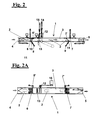
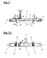
- figures from 1 to 6, show a diagrammatical longitudinal sectional view of a duct according to the invention for orientation of a sock in various steps of the orienting method;
- figures from 1A to 6A show a top plan view of the diagrammatical view of figures from 1 to 6 in the respective operative steps;
- figures 7,7A and 7B show a possible scanning view of an end of the sock;
- figure 8 shows a flow-sheet of the scanning, orienting operations of the sock and for feeding it correctly to the loading unit on a finishing machine;
- figure 9 shows an embodiment of the invention wherein two array of sensors are provided upstream and downstream of the dragging rollers, for allowing a comparison between the scanning diagram of the tip portion and of the band portion; figure 10 shows a further embodiment of the invention wherein the sensors operate according to directions parallel to the plane of the sock, for scanning different heights of the side profile of the tip portion or of the band portion.
- For the longitudinal orientation of a
sock 2 anapparatus 1 is provided shown diagrammatically in figures 1 and 1A. It comprises aduct 3 having afirst mouth 4 and asecond mouth 5 that have valves for allowing in theduct 3 air currents that are directed in either directions. - The
duct 3 has afirst grid 6 and asecond grid 7 rotatable with respect to pins 6' and 7'. - At the
grids devices elements - A
dragging device 12 is provided having pinch-rollers associated to a device ofdetection 13 of the profile of the socks. Thedragging device 12 can be lowered or raised by means of apiston 14, whereas the device ofdetection 13 can be lowered or raised by means of apiston 15. - The process of longitudinal orientation begins with picking up
sock 2, for example by a sucker from a container (not shown in the figure) and its introduction in aduct 3. The various steps are summarized also in the diagram of figure 8. - The socks that enter in the
duct 3 by means of an air flow fromgrid 6 togrid 7, then hit against thegrid 7 that is in closed position (see figures 2 and 2A). Thegrasping device 9 moveselement 10 in order to grasp one sock. In presence of more socks, that can be detected by means of optical sensors that consider the volume occupied by the mass of socks, an air jet is delivered in a direction of thefirst grid 6, that is in raised position, so that all thefurther socks 2 are rejected through the duct 3 (see figures 3 and 3A). - With reference to figures 4 and 4A, when the socks in excess have left the
duct 3, thefirst grid 6 is closed and thesock 2 previously grasped is released and hits againstfirst grid 6. Then, thesock 2 is grasped by the other graspingdevice 8 and the air flow is inverted, i.e. fromgrid 6 towardsgrid 7, whereby thesock 2 is stretched longitudinally. For assuring the stretching condition, the operations now described between the two grids can be repeated, so that the sock is effectively stretched and is not grasped bydevice 8 in a central zone. - When
sock 2 is still being grasped, the dragging means 12 are lowered, whereby thesock 2 is dragged in the direction towardssecond grid 7, whereas the air flow stops momentarily, and contemporaneously with dragging means 12 the sensor means 13 carry out a scanning step of the sock 2 (see figures 5, 5A, 7, 7A, 7B). - To assure that
sock 2 is oriented correctly and can then proceed for successive steps of the production cycle, it is necessary that tip portion 2' (see figure 7A) is arranged according to the direction ofsecond grid 7. In other words, thesensors 13 must detect the presence of the portion 2' from its contour oriented towardsgrid 6, this meaning that the band portion is oriented correctly towards grid 7 (see figures 6 and 6A). - In this case,
second grid 7 opens and under an air flow directed fromgrid 6 togrid 7 the sock is pushed away fromduct 3, towards a loading station where steaming forms or handling forms are present. Otherwise,sock 2 is pushed in an opposite direction and, by a deviatingflap 4, enters an inversion duct that brings it with the band portion oriented forward towards the loading station. - With reference to figure 9, according to a different embodiment of the invention, two arrays of
sensors 13 and 13' are provided respectively upstream and downstream of the draggingrollers 12, for allowing a comparison between the scanned shape of the tip portion 2' and of the band portion. This way, it is possible to orient socks that have only a slight difference between tip portion and band portion. The double scanning increases the detection precision when the sock tends to traverse obliquely in the duct. - As shown in figure 10, according to a further embodiment of the invention,
sensors sock 2 for detecting different heights of the side profile of the tip portion 2' or of the band portion. In fact, in many types of socks the tip portion, not yet steamed, tends to fold owing to the different tension of the knitted zones of the tip. This difference can be detected alternatively or in addition to the solution previously described, wherein the sensors are oriented in a direction orthogonal to the plane of the sock. - The foregoing description of a specific embodiment will so fully reveal the invention according to the conceptual point of view, so that others, by applying current knowledge, will be able to modify and/or adapt for various applications such an embodiment without further research and without parting from the invention, and it is therefore to be understood that such adaptations and modifications will have to be considered as equivalent to the specific embodiment. The means and the materials to realise the different functions described herein could have a different nature without, for this reason, departing from the field of the invention. It is to be understood that the phraseology or terminology employed herein is for the purpose of description and not of limitation.
Claims (18)
- A method for longitudinal orientation of tubular knitted elements such as socks (2), knee socks or the like, said tubular elements having two respective ends as a tip portion (2') and a band portion, comprising the steps of:preliminarily stretching the sock (2) in a duct (3) of orientation, whereby the sock (2) is present in the duct (3) of orientation with its two ends aligned longitudinally;detecting by means of sensors (13) the position of an end that is either a tip portion (2') or a band portion;after the detecting step, conveying the sock (2) in the duct (3) in a direction according to which the position is known of the band portion with respect to the tip portion (2'), whereby before the introduction of the sock (2) in a loading duct (3) a step is provided of inversion of the sock (2) if the band portion is not oriented in the chosen direction, or a step of rejection.
- Method according to claim 1, wherein for conveying the sock (2) an air flow is selectively sent in the duct (3) of orientation whereby the sock (2) proceeds in the duct (3) in either one or the other direction and is then deviated into a loading duct (3) so that it is conveyed in the loading duct (3) with band portion and tip portion (2') oriented in a predetermined way by said sensor means.
- Method according to claim 1, wherein the preliminary stretching step of the sock (2) is carried out by means of an air flow after preliminarily grasping a first end thereof, whereby the second end engages said sensor means.
- Method according to claim 1, wherein for carrying out said detecting step a mechanical dragging step is provided (12) starting from its second end through said sensors (13) that carry out a scanning of at least part of the first end thereof.
- Method according to claim 1, wherein said sensors carry out a contemporaneous scanning of said sock upstream and downstream of said dragging means (12), whereby the profiles can be at the same time detected of said first and second end and a comparison between them is made.
- Method according to claim 4, wherein after said preliminary stretching step the sock extends with said second end between dragging means (12), the latter pinching said second end and dragging the sock (2) after that the air flow has stopped, the first end being left free and the sensor means (13) scan the sock (2) in the portion set between said first and said second end.
- Method according to claim 5, wherein for a correct scanning the sock (2) is pressed between the sensor means (13) during the dragging step, for stretching any possible folds and improving the scanning conditions.
- Method according to claim 1, wherein the sock (2) after said preliminary stretching step moves substantially in a plane, said sensors (13) scanning at least a portion of said sock (2) orthogonally to said plane, whereby said sensors recognise the plan profile of said tip portion (2') or of said band portion.
- Method according to claim 1, wherein the sock (2) after said preliminary stretching step moves substantially in a plane, said sensors (13) scanning at least a portion of said sock (2) parallel to said plane, whereby said sensors recognise different heights of the side profile of said tip portion (2') or of said band portion.
- Apparatus for longitudinal orientation of a sock (2) according to the one of the previous claims, comprising:a duct (3) of orientation wherein said sock (2) is present with its two ends aligned longitudinally,sensor means (13) for scanning the profile of said sock (2) at one end of said sock (2) and determining whether it is a tip portion (2') or a band portion,means for creating selectively an air flow in said duct (3) of orientation that drags said sock (2) in a predetermined way and brings it in a loading duct (3),means for deviating said sock (2) so that it enters said loading duct (3) with tip portion (2') and band portion oriented in a predetermined way .
- Apparatus according to claim 10, wherein mechanical dragging means (12) of the sock (2) are also provided along said duct (3) of orientation and through said sensor means (13), the latter detecting the profile of at least one part of said sock (2) at the passage controlled by said dragging means (12).
- Apparatus according to claim 11, wherein said dragging means (12) comprise at least two dragging rollers that pinch said sock (2) and convey it so that at least a portion thereof passes through said sensor means (13).
- Apparatus according to claim 11, wherein said sensor means are grouped as first sensors upstream of said dragging means (12) and seconds sensors downstream said dragging means (12), whereby the profiles can be at the same time measured of said first and second end and a comparison between them is made.
- Apparatus according to claim 12, wherein said sensor means (13) comprise a head that pushes said sock (2) against a counter-surface belonging to said duct (3), whereby said sock (2) is dragged between said head and said counter-surface for stretching any possible folds and for allowing a correct detection of its profile.
- Apparatus according to claim 12, wherein means are provided for stretching the sock (2) in said duct (3) comprising:means for grasping a first end thereof leaving the second end free,means for creating an air flow from the first to the second end;means for blocking said dragging means (12) against said second end stretched by said air flow, said dragging means (12) dragging the sock (2) after that the air flow has stopped, the first end being left free, the sensor means (13) scanning at least one part of said sock that crosses them.
- Apparatus according to claim 10, wherein in said duct (3) of orientation two grids are provided (6,7) movable between an open position and a closed position, at each grid (6,7) grasping means being provided (8,9), the sensor means (13) and the dragging means (12) being arranged between said two grids (6,7).
- Apparatus according to claim 10, wherein said sensor means (13) comprise an array of sensors (13) with a density that allows a sufficient definition of the contour of at least a portion of the sock (2).
- Apparatus according to claim 10, wherein said sensor means (13) are chosen among: optical sensors (13), mechanical sensors (13), pneumatic sensors (13), electrical sensors (13).
Applications Claiming Priority (2)
| Application Number | Priority Date | Filing Date | Title |
|---|---|---|---|
| IT2001PI000021A ITPI20010021A1 (en) | 2001-03-21 | 2001-03-21 | METHOD AND EQUIPMENT FOR THE LONGITUDINAL ORIENTATION OF FOOTWEAR ITEMS |
| ITPI010021 | 2001-03-21 |
Publications (2)
| Publication Number | Publication Date |
|---|---|
| EP1243682A2 true EP1243682A2 (en) | 2002-09-25 |
| EP1243682A3 EP1243682A3 (en) | 2003-07-09 |
Family
ID=11452998
Family Applications (1)
| Application Number | Title | Priority Date | Filing Date |
|---|---|---|---|
| EP02006372A Withdrawn EP1243682A3 (en) | 2001-03-21 | 2002-03-21 | Method and apparatus for longitudinal orientation of hosiery articles |
Country Status (3)
| Country | Link |
|---|---|
| US (1) | US6719177B2 (en) |
| EP (1) | EP1243682A3 (en) |
| IT (1) | ITPI20010021A1 (en) |
Cited By (5)
| Publication number | Priority date | Publication date | Assignee | Title |
|---|---|---|---|---|
| WO2005100664A1 (en) * | 2004-04-16 | 2005-10-27 | Golden Lady Company S.P.A. | Machine for handling tubular knitted articles, such as socks or the like |
| WO2007000782A1 (en) * | 2005-06-29 | 2007-01-04 | Golden Lady Company S.P.A. | Device for handling tubular knitted articles, in particular socks and the like |
| WO2007020668A1 (en) * | 2005-08-19 | 2007-02-22 | Golden Lady Company S.P.A. | Device for longitudinally spreading a flexible article, such as a tubular knitted article |
| WO2007135702A1 (en) * | 2006-05-19 | 2007-11-29 | Golden Lady Company S.P.A. | Method and device to discriminate two ends of an article from each other |
| CN101522975B (en) * | 2006-10-13 | 2013-01-30 | 金莱迪公司 | Device and method to align the edge surrounding an end of a tubular knitted article |
Families Citing this family (7)
| Publication number | Priority date | Publication date | Assignee | Title |
|---|---|---|---|---|
| ITFI20020106A1 (en) * | 2002-06-18 | 2003-12-18 | Matec Spa | DEVICE AND METHOD FOR DETECTING THE ORIENTATION OF MANUFACTURERS SUCH AS MEN'S SOCKS AND SOCKS |
| RU2006140369A (en) * | 2004-04-16 | 2008-05-27 | Голден Лейди Компани С.П.А. (It) | INSTALLATION FOR PROCESSING HOLLOW KNITTED ITEMS, SUCH AS SOCKS OR SOMETHING |
| WO2007020667A1 (en) * | 2005-08-19 | 2007-02-22 | Golden Lady Company S.P.A. | Device and method for handling tubular knitted articles, such as stockings and socks or the like |
| ITFI20060132A1 (en) * | 2006-05-31 | 2007-12-01 | Golden Lady Co Spa | METHOD AND DEVICE TO PNEUMATICALLY RELEASE A FLEXIBLE EXTENDED MANUFACTURE, SUCH AS A SOCK OR SOCK |
| US20110131922A1 (en) * | 2008-08-27 | 2011-06-09 | Doeka Asia Sdn. Bhd. | Device for separating and packing elastic products |
| IT201900006700A1 (en) * | 2019-05-09 | 2020-11-09 | Cortese S R L | METHOD AND APPARATUS FOR PAIRING MEN'S SOCKS |
| CN113862906A (en) * | 2021-08-27 | 2021-12-31 | 宁波考比锐特智能科技有限公司 | Sock seam turning and fixing integrated machine |
Citations (6)
| Publication number | Priority date | Publication date | Assignee | Title |
|---|---|---|---|---|
| US4611733A (en) * | 1984-06-22 | 1986-09-16 | Takatori Machinery Mfg. Co., Ltd. | Apparatus for automatically relocating the stocking toe part correctly on the setting frame |
| US5511501A (en) * | 1994-04-05 | 1996-04-30 | Monarch Knitting Machinery Corporation | Method and apparatus for handling flexible objects |
| US5884822A (en) * | 1996-07-09 | 1999-03-23 | Matec S.R.L. | Method and apparatus for picking up and moving tubular articles |
| US5992712A (en) * | 1997-07-10 | 1999-11-30 | Takatori Corporation | Method and apparatus for processing hose material |
| EP1178143A2 (en) * | 2000-07-21 | 2002-02-06 | Matec Spa | Method for detecting the orientation of a textile product having two different ends, apparatus for implementing said method and orientator device associated with said apparatus |
| EP1221502A2 (en) * | 2001-01-03 | 2002-07-10 | Threadbear, L.L.C. | Method and apparatus for detecting and controlling orientation of articles for further processing |
Family Cites Families (3)
| Publication number | Priority date | Publication date | Assignee | Title |
|---|---|---|---|---|
| US3704565A (en) * | 1970-08-24 | 1972-12-05 | Intech Corp | Method of and apparatus for producing hosiery |
| IT1283271B1 (en) * | 1996-03-18 | 1998-04-16 | Essedue S R L | PNEUMATIC FEEDING DEVICE FOR SOCKS, USED WITH PNEUMATIC TRANSPORT SYSTEMS OF AD SOCKS |
| DE19627812A1 (en) * | 1996-07-11 | 1998-01-15 | Wepamat Maschinenbau Gmbh | Method and device for aligning essentially tubular textile goods |
-
2001
- 2001-03-21 IT IT2001PI000021A patent/ITPI20010021A1/en unknown
-
2002
- 2002-03-21 EP EP02006372A patent/EP1243682A3/en not_active Withdrawn
- 2002-03-21 US US10/104,753 patent/US6719177B2/en not_active Expired - Fee Related
Patent Citations (6)
| Publication number | Priority date | Publication date | Assignee | Title |
|---|---|---|---|---|
| US4611733A (en) * | 1984-06-22 | 1986-09-16 | Takatori Machinery Mfg. Co., Ltd. | Apparatus for automatically relocating the stocking toe part correctly on the setting frame |
| US5511501A (en) * | 1994-04-05 | 1996-04-30 | Monarch Knitting Machinery Corporation | Method and apparatus for handling flexible objects |
| US5884822A (en) * | 1996-07-09 | 1999-03-23 | Matec S.R.L. | Method and apparatus for picking up and moving tubular articles |
| US5992712A (en) * | 1997-07-10 | 1999-11-30 | Takatori Corporation | Method and apparatus for processing hose material |
| EP1178143A2 (en) * | 2000-07-21 | 2002-02-06 | Matec Spa | Method for detecting the orientation of a textile product having two different ends, apparatus for implementing said method and orientator device associated with said apparatus |
| EP1221502A2 (en) * | 2001-01-03 | 2002-07-10 | Threadbear, L.L.C. | Method and apparatus for detecting and controlling orientation of articles for further processing |
Cited By (5)
| Publication number | Priority date | Publication date | Assignee | Title |
|---|---|---|---|---|
| WO2005100664A1 (en) * | 2004-04-16 | 2005-10-27 | Golden Lady Company S.P.A. | Machine for handling tubular knitted articles, such as socks or the like |
| WO2007000782A1 (en) * | 2005-06-29 | 2007-01-04 | Golden Lady Company S.P.A. | Device for handling tubular knitted articles, in particular socks and the like |
| WO2007020668A1 (en) * | 2005-08-19 | 2007-02-22 | Golden Lady Company S.P.A. | Device for longitudinally spreading a flexible article, such as a tubular knitted article |
| WO2007135702A1 (en) * | 2006-05-19 | 2007-11-29 | Golden Lady Company S.P.A. | Method and device to discriminate two ends of an article from each other |
| CN101522975B (en) * | 2006-10-13 | 2013-01-30 | 金莱迪公司 | Device and method to align the edge surrounding an end of a tubular knitted article |
Also Published As
| Publication number | Publication date |
|---|---|
| US6719177B2 (en) | 2004-04-13 |
| US20020148864A1 (en) | 2002-10-17 |
| EP1243682A3 (en) | 2003-07-09 |
| ITPI20010021A1 (en) | 2002-09-21 |
Similar Documents
| Publication | Publication Date | Title |
|---|---|---|
| US6719177B2 (en) | Method and apparatus for longitudinal orientation of hosiery articles | |
| US5165355A (en) | Method and apparatus for handling hosiery blanks | |
| JPH04276289A (en) | Conveying method, positioning method, setting apparatus, transfer apparatus, handling apparatus and conveying apparatus for cylindrical member | |
| US3704565A (en) | Method of and apparatus for producing hosiery | |
| US7412789B2 (en) | Process for aligning a laundry article and device for carrying out the process | |
| EP1421231A1 (en) | Device for transferring a tubular knitted article from the machine where it is made to means for closing the toe | |
| EP0184340A2 (en) | Transfer mechanism for and method of transferring hosiery articles | |
| US5511501A (en) | Method and apparatus for handling flexible objects | |
| US5771830A (en) | Method and apparatus for manipulating a length of flexible material | |
| WO2009141842A1 (en) | Method and device for reversing tubular articles, such as socks and stockings, after closure of the toe | |
| US7290409B2 (en) | Method and device for handling a tubular knitted article, in particular a sock | |
| US20110158785A1 (en) | Apparatus for automatic transfer of textile articles from a linking machine to a boarding machine | |
| ITRM980346A1 (en) | PROCEDURE AND EQUIPMENT FOR PROCESSING TEXTILE MATERIAL IN TUBULAR FORM | |
| US3806009A (en) | Method and apparatus for handling hosiery | |
| US6820497B2 (en) | Method and apparatus for detecting and controlling orientation of articles for further processing | |
| US5544603A (en) | Apparatus for handling flexible objects | |
| JP2005501187A (en) | Method and apparatus for opening an edge of a tubular knitted article or similar article | |
| US5373977A (en) | Method for transferring pantyhose from a line closer machine to a toe-closer machine and apparatus for the implementation thereof | |
| US3768226A (en) | Flat folding & stacking method and apparatus | |
| EP1375722B1 (en) | Apparatus and method for detecting the orientation of textile products such as stockings and socks | |
| JPH03245885A (en) | Apparatus for removing fallen bottle | |
| US3426552A (en) | Hosiery take-up and delivery apparatus | |
| KR20200020923A (en) | Textile automatic spreader | |
| US5477996A (en) | Method and apparatus for automatically positioning stockings in a pantyhose-forming machine | |
| US6334547B1 (en) | Method and apparatus for manipulating a length of flexible material |
Legal Events
| Date | Code | Title | Description |
|---|---|---|---|
| PUAI | Public reference made under article 153(3) epc to a published international application that has entered the european phase |
Free format text: ORIGINAL CODE: 0009012 |
|
| AK | Designated contracting states |
Kind code of ref document: A2 Designated state(s): AT BE CH CY DE DK ES FI FR GB GR IE IT LI LU MC NL PT SE TR |
|
| AX | Request for extension of the european patent |
Free format text: AL;LT;LV;MK;RO;SI |
|
| PUAL | Search report despatched |
Free format text: ORIGINAL CODE: 0009013 |
|
| AK | Designated contracting states |
Designated state(s): AT BE CH CY DE DK ES FI FR GB GR IE IT LI LU MC NL PT SE TR |
|
| AX | Request for extension of the european patent |
Extension state: AL LT LV MK RO SI |
|
| 17P | Request for examination filed |
Effective date: 20040107 |
|
| AKX | Designation fees paid |
Designated state(s): DE ES FR GB IT TR |
|
| RBV | Designated contracting states (corrected) |
Designated state(s): DE ES FR GB IT |
|
| 17Q | First examination report despatched |
Effective date: 20060928 |
|
| 17Q | First examination report despatched |
Effective date: 20060928 |
|
| RAP1 | Party data changed (applicant data changed or rights of an application transferred) |
Owner name: SANTONI S.P.A. |
|
| GRAP | Despatch of communication of intention to grant a patent |
Free format text: ORIGINAL CODE: EPIDOSNIGR1 |
|
| STAA | Information on the status of an ep patent application or granted ep patent |
Free format text: STATUS: THE APPLICATION IS DEEMED TO BE WITHDRAWN |
|
| 18D | Application deemed to be withdrawn |
Effective date: 20080722 |