EP0184263A1 - Device for transporting a flexible strip - Google Patents
Device for transporting a flexible strip Download PDFInfo
- Publication number
- EP0184263A1 EP0184263A1 EP85201980A EP85201980A EP0184263A1 EP 0184263 A1 EP0184263 A1 EP 0184263A1 EP 85201980 A EP85201980 A EP 85201980A EP 85201980 A EP85201980 A EP 85201980A EP 0184263 A1 EP0184263 A1 EP 0184263A1
- Authority
- EP
- European Patent Office
- Prior art keywords
- strip
- pressure
- rollers
- coupling member
- force
- Prior art date
- Legal status (The legal status is an assumption and is not a legal conclusion. Google has not performed a legal analysis and makes no representation as to the accuracy of the status listed.)
- Granted
Links
Images


Classifications
-
- G—PHYSICS
- G01—MEASURING; TESTING
- G01D—MEASURING NOT SPECIALLY ADAPTED FOR A SPECIFIC VARIABLE; ARRANGEMENTS FOR MEASURING TWO OR MORE VARIABLES NOT COVERED IN A SINGLE OTHER SUBCLASS; TARIFF METERING APPARATUS; MEASURING OR TESTING NOT OTHERWISE PROVIDED FOR
- G01D15/00—Component parts of recorders for measuring arrangements not specially adapted for a specific variable
- G01D15/28—Holding means for recording surfaces; Guiding means for recording surfaces; Exchanging means for recording surfaces
-
- B—PERFORMING OPERATIONS; TRANSPORTING
- B41—PRINTING; LINING MACHINES; TYPEWRITERS; STAMPS
- B41J—TYPEWRITERS; SELECTIVE PRINTING MECHANISMS, i.e. MECHANISMS PRINTING OTHERWISE THAN FROM A FORME; CORRECTION OF TYPOGRAPHICAL ERRORS
- B41J13/00—Devices or arrangements of selective printing mechanisms, e.g. ink-jet printers or thermal printers, specially adapted for supporting or handling copy material in short lengths, e.g. sheets
- B41J13/26—Registering devices
- B41J13/30—Side lays or gauges
-
- B—PERFORMING OPERATIONS; TRANSPORTING
- B41—PRINTING; LINING MACHINES; TYPEWRITERS; STAMPS
- B41J—TYPEWRITERS; SELECTIVE PRINTING MECHANISMS, i.e. MECHANISMS PRINTING OTHERWISE THAN FROM A FORME; CORRECTION OF TYPOGRAPHICAL ERRORS
- B41J15/00—Devices or arrangements of selective printing mechanisms, e.g. ink-jet printers or thermal printers, specially adapted for supporting or handling copy material in continuous form, e.g. webs
- B41J15/16—Means for tensioning or winding the web
Definitions
- the invention relates to a device for transporting a flexible strip along a guide provided with at least two conical pressure rollers which are rotable about an axis at right angles to the transport direction of the strip, which engage under resilient force the strip located on transport rollers and a support, whose apices face each other and which are made at least at the area of the pressure contact with the strip of an elastically deformable material, the force exerted by one pressure roller on the strip differing from the force exerted by the other pressure roller on the strip.
- the known device has the disadvantage that the difference in pressure force due to tolerances in the rigidity and the dimensions of the two springs not always has that value which is desirable for obtaining an optimum guidance (directional effect) and for holding the strip taut to the optimum.
- the invention has for its object to avoid the said disadvantage.
- the invention is for this purpose characterized in that a spring common to both pressure rollers exerts via at least one coupling member different forces on the pressure rollers.
- the invention is based on the recognition of the fact that, when for both pressure rollers use is made of only one spring, no spring tolerances need be taken into account, which in the most unfavourable case would be summed.
- the difference in pressure forces can thus be kept within comparatively narrow limits.
- the European Patent Application 0102022 discloses a device in which use is also made of a separate spring for each pressure roller. However, there is not intentionally applied a difference in pressure force for obtaining a directional effect towards the guide. Such a directional effect may occur in this case unintentionally and incidentally due to spring tolerances. It will be appreciated that in such a case no directional effect of a predetermined strength is obtained. The known device is therefore solely intended to hold the strip taut.
- US-PS 3929327 discloses a device in which a directional effect towards a guide is obtained by means of a single elastically deformable conical roller. In this case, there is no question of simultaneously directing and stretching the strip.
- a particular embodiment of the device according to the invention which supplies an additional stretching force and directional effect on the strip, is further characterized in that one pressure roller is rotatably journalled in a first tiltable lever-shaped coupling member having a first lever arm, while the other pressure roller is journalled in a second tiltable lever-shaped coupling member having a second lever arm different from the first lever arm, one end of the common spring exerting a tensile force on the first coupling member and the other end of the spring exerting a tensile force on the second coupling member.
- a preferred embodiment of the device according to the invention in which the axis of rotation of the pressure rollers invariably crosses the transport direction of the strip perpendicularly, is further characterized in that each of the coupling members is tiltable about a line which crosses the axis of rotation of the relevant pressure roller perpendicularly and which is parallel to the transport direction of the strip and is constituted by the connection line between two pivots of the coupling member.
- a further embodiment of the invention having a comparatively compact construction is characterized in that the coupling member consists of a movable bridge which is coupled with both pressure rollers and is subjected to an asymmetrical pressure force by the common spring, this bridge being provided with positioning rollers which are supported by roller surfaces of rotatable connection arms which support the rotatable pressure rollers.
- the device shown in Figure 1 is a device for transporting strip-shaped information carriers (for example paper strips) and is preferably used in so-called writing recording devices and printing devices.
- recording devices a possibility is the automatic recording of measurement results, but also the display of graphs, diagrams and images visible on a monitor.
- writing pins For recording and displaying, use is made of writing pins.
- printing devices printing devices
- a possibility resides in matrix printers having impact members or thermal printing members, optical printers having a photo-sensitive information carrier or electronic typewriters. Such printers may be computer-controlled.
- the device shown in Figure 1 has a frame 1 with a bottom 3 and two parallel side walls 5 and 7 arranged at right angles thereto.
- a beam 2 extends at right angles to the side walls 5 and 7, while along this beam a printing head 4 is guided, which is shown only diagrammatically. For the sake of clarity, the front wall and the rear wall of the transport device and the printing or writing members are not shown.
- a plate-shaped support 9 for a paper strip 11 which is supplied from a paper supply 13.
- the paper supply 13 consists of a stack of telescopically folded paper.
- the side wall 5 has secured to it a strip-shaped transverse guide 15 for the paper strip 11, whose plane is at right angles to the plane of the support 9 parallel to the bottom 3.
- the transverse guide 15 extends parallel to the transport direction of the paper strip 11, which is indicated by an arrow 17.
- the transverse guide 15 may also be integrated in the side wall 5 and may constitute the upper part thereof, as is shown in Figures 2 and 3, or may form part of one of the coupling members described below.
- a console 19 secured to the side wall 5 forms a support for a first lever-shaped coupling member 21, while a console 23 secured to the side wall 7 forms a support for a second lever-shaped coupling member 25.
- the coupling members 21 and 25 are preferably made of a transparent material for the sake of the visibility of the printed information.
- the first coupling member 21 comprises a plate-shaped paper guide 27, which is parallel to the support 9, and a transverse partition wall 29 and a longitudinal partition wall 31. Both partition walls 29 and 31 are at right angles to the paper guide 27.
- the transverse partition wall is at right angles to the paper transport direction 17, while the longitudinal partition wall 31 is parallel thereto.
- the paper guide 27 has secured on it a U-shaped bracket 33, in which a first conical pressure roller 35 is rotatably journalled.
- the second coupling member 25 comprises a plate-shaped paper guide 37 which is parallel to the support 9 as well as a transverse partition wall 39 and a longitudinal partition wall 41. Both partition walls 39 and 41 are at right angles to the paper guide 37.
- the transverse partition wall 39 is at right angles to the paper transport direction 17, while the longitudinal partition wall 41 is parallel thereto.
- the paper guide 37 has secured on it a U-shaped bracket 43, in which a second conical pressure roller 45 is rotatably journalled.
- the axes of rotation of the conical rollers 35 and 45 whose apices face each other, are in line with each other and cross the paper transport direction 17 perpencidularly.
- Two driving rollers 49 and 51 corresponding to the pressure rollers 35 and 45 are secured on a driving shaft 47 rotatably journalled in the side walls 5 and 7.
- the axes of rotation of the pressure rollers 35 and 45 are parallel to the driving shaft 47.
- the paper guides 27 and 37 windows 53 and 55 are provided, through which the pressure rollers 35 and 45 are passed (see Figures 2 and 3).
- the support 9 is provided with windows 57 and 59, through which the driving rollers 49 and 51 are passed (see Figure 3).
- the paper strip 11 is located between the pressure rollers 35 and the corresponding driving roller 49 and between the pressure roller 45 and the corresponding driving roller 51.
- the pressure contact between the pressure rollers 35 and 45 and the paper strip 11 and the driving rollers 49 and 51, respectively, is obtained by means of the coupling members 21 and 25.
- the coupling members 21 and 25 are tiltable about tilting lines 61 and 63, respectively, by means of a tensile spring 65.
- the tilting line 61 is constituted by the connection line between two pivots 67 and 69, while the tilting line 63 is constituted by the connection line between two pivots 71 and 73.
- FIG 4 a detail of the substantially identical pivots 67, 69, 71 and 73 is shown.
- Each of the pivots is constituted by a sphere section 75 which is provided with a cylindrical part 77 welded in a cylindrical dish 79 with an annular collar 81 of the fixedly arranged consoles 19 and 23.
- the paper guides 27 and 37 there are formed two openings 83, of which the boundary walls form a section of a conical surface. The paper guides 27 and 37 can consequently slide along the walls of the openings 83 and can thus tilt about the tilting lines 61 and 63.
- the coupling members 21 and 25 act as lever, which are rotatable about the tilting lines 61 and 63.
- the distances A and B, respectively (see Figure 3) between the pressure points of the conical rollers 35 and 45 and the tilting lines 61 and 63 are different so that the lever arms are also different.
- the length of the first lever arm is consequently equal to A, while the length of the second lever arm is equal to B.
- the directional force on the paper strip in the direction 85 is also accurately defined and the risk of bulging and folding or rumpling, respectively, of the paper strip 11 due to ar excessively large engagement force against the transverse guide 15 is considerably reduced.
- the triangles formed by the two pivots and the centre of the relevant pressure rollers are triangles which are rotatable about the relevant tilting lines (see Figure 2).
- the conical pressure rollers 35 and 45 are preferably obtained by injection-moulding from silicon rubber or polyurethane and are secured on the relevant rotary shaft by means of a bearing bush.
- the pressure rollers have a cylindrical part which adjoins a conical part (section of a cone) and establishes the connection with the said bearing bush.
- the conical part of the pressure rollers is preferably 5 made hollow in order to obtain a sufficiently large deformability. This is desirable in connection with the desired size of the contact area with the paper strip. Hollow conical pressure rollers are otherwise known per se from the aforementioned US-PS 3929327.
- the driving rollers 49 and 51 are preferably made of steel. For the sake of a good application to the paper strip, the driving rollers are provided with a longitudinal knurl which may be hardened. This permits the so-called "breathing" of the paper in transverse direction at comparatively low transport speeds and under changing climatologic conditions.
- the pivots 67,69,71 and 73 are kept free of clearance. Since the tensile force F applies in a vertical plane through the pivots 67 and 71, the reaction force in the pivots 69 and 73 is comparatively small. This force can be added to a pre-tension force of dish springs (not shown) arranged at the area of the pivots 69 and 73 between the consoles 19 and 23 and the paper guides 27, 37.
- the tensile force F s would preferably have to apply in a vertical plane halfway between the pivots 67,69 and the pivots 71,73 from a viewpoint of distribution of forces, this is not the case for the sake of the visibility of the printed information and the possibility of recording annotations directly beside the printed information.
- the paper guides 91 guide the paper strip 11 from the stack 13 to the support 9. With a transport which takes place in a direction opposite to the direction 17, the paper guides 91 favour the formation of the stack 13.
- the paper guides 91 may be replaced by a curved plate.
- the paper guides 27 and 37 with the pressure rollers 35 and 45 can be lifted so that the paper strip 11 can readily be removed.
- the rod 95 is provided for this purpose near the lefthand and the righthand end with tongues 99 and 101 which upon rotation of the rod 95 are in engagement with tongues 103 and 105 formed at the coupling members 21 and 25.
- the coupling members 21 and 25 are tilted about the tilting lines 61 and 63 (see also Figure 5).
- a cam follower (not shown further) on the laterally displaceable rod 95 and a cam on the coupling members 21 and 25, the rod 95 can be locked in the position indicated by dotted lines.
- the alternative embodiment of the device according to the invention shown in Figures 6, 7 and 8, which is provided as far as possible with reference numerals corresponding to those in the preceding Figures, has only one coupling member 109 in the form of a bridge.
- the bridge 109 is constituted by a transverse rod 111 which is passed through openings in the side walls 5 and 7 and has two arms 113 and 115 which are at right angles to the transverse rod 111.
- the arms 113 and 115 have secured to them rotatable positioning rollers 117 and 119, by means of which the bridge 109 can be moved over roller surfaces of strip-shaped connection arms 121 and 123.
- connection arms 121 and 123 are secured to shafts 125 and 127 which are rotatably journalled in the side walls 5 and 7 (see Figure 6).
- the conical pressure rollers 35 and 45 are rotatably journalled on rods 129 and 131 rigidly connected to the connection arms 121 and 123.
- the windows 57 and 59 through which the driving rollers 49 and 51 are passed, which are in pressure contact with the conical pressure rollers 35 and 45.
- the transverse guide 15 (see Figure 1) is constituted in the present case by the side wall 5. Since the compression spring 135 is arranged asymmetrically at a distance A from the positioning roller 117 and at a distance B from the positioning roller 121, where A is smaller than B, the driving rolller 49 is subjected to a larger pressure force by the pressure roller 35 then that to which the driving roller 51 is subjected by the pressure roller 45. When the pressure force of the spring 135 is made equal to F , the pressure forces F L and F R exerted by the pressure rollers 35 and 45 satisfy the relations:
- the positioning rollers 117 and 119 are in the position shown in Figure 6, in which the parallel connection lines between the axes of rotation of the positioning rollers 117 and 119 and between the axes of rotation of the pressure rollers 35 and 45 are located in the same vertical plane.
- the centre line of the driving shaft 47 is also located in this vertical plane.
- the said connection lines and the said centre line are consequently shifted, projected on the horizontal plane, with respect to the connection line between the rotary shafts 125 and 127 of the rotatable connection arms 121 and 123.
- connection arms 121 and 123 rotate about the shafts 125 and 127 and the pressure rollers 35 and 45 are simultaneously lifted of the paper strip 11 (not shown in Figure 6) and the driving rollers 49 and 51.
- the paper strip 11 can then readily be removed.
- Figure 8 illustrates how the bridge 109 can be moved over the connection arms 121 and 123.
- the positioning rollers 117 and 119 (see also Figures 6 and 7) are rotatably journalled on-stub shafts 137 and 139 which are secured to arms 113 and 115.
- each of shafts 137 and 139 is pivotable about the centre of rotation of a pin 143, which is slidably and rotatably guided in a slot 145 in the side walls 5 and 7.
- a pin 143 which is slidably and rotatably guided in a slot 145 in the side walls 5 and 7.
- the lever 141 is a prolonged part of the arms 113 and 115.
- the pin 143 is secured to the lever 141.
- connection arms 121 and 123 Due to the pressure force of the spring 135, the connection arms 121 and 123 are rotated about the shafts 125 and 127 as soon as the positioning rollers 117 and 119 pass the arms 125 and 127.
- the pin 143 slides during this rotational movement upwards in the slot 145 whilst simultaneously rotating. It will be appreciated that the levers 141 are held by the spring 135 in the position shown in dotted lines until they are manually returned to the vertical position.
- the invention provides a transport device for writing and printing devices, in which the directional force and the pressure force are strongly independent of spring tolerances, whilst moreover component parts are saved.
- the said forces can be kept sufficiently accurately within the desired limits in the wide range of transport speeds (up to 2 m/sec) occurring in practice. Thus, the risk of bulging and meandering paper is considerably reduced.
- the invention is described with reference to a transport device for writing and printing devices, in which standard paper is used, it is not limited thereto.
- the invention can be used in the transport of flexible information strips both of comparatively large and small length. In the latter case, information sheets or sheet-like information strips are concerned. Due to the fact that the transport device ensures that a longitudinal edge of the information carrier engages thesaid transverse guide, the beginning of printing or writing information always occurs at a defined area of the information carrier.
- Theinformation carrier may be constituted by the conventional paper or by multi-layer strips with, for example, a dielectric layer, a heat-sensitive layer or a pressure-sensitive layer for electrostatic, thermal or impact printing arrangements.
- the heat transfer to the information carrier can be obtained by means of a so-called thermal printing head or laser printing head.
- Printing devices in which ink drops are used, are also included.
- the term "flexible strip” does not include those strips in which the magnetization of a layer is varied by a magnetic printing head.
- those flexible strips should be excluded which are provided for the manufacture of clothing or . fabrics with a print or a pattern.
- flexible strips such as credit cards and other official documents, which are provided with a print or a pattern, are also included.
- the printed strip has to comprise information or data, although, as already stated, this strip is not of magnetic nature.
Abstract
Description
- The invention relates to a device for transporting a flexible strip along a guide provided with at least two conical pressure rollers which are rotable about an axis at right angles to the transport direction of the strip, which engage under resilient force the strip located on transport rollers and a support, whose apices face each other and which are made at least at the area of the pressure contact with the strip of an elastically deformable material, the force exerted by one pressure roller on the strip differing from the force exerted by the other pressure roller on the strip.
- In the "Hewlett-Packard Journal" of December 1982,
pages 29 and 30, a device is described of the kind mentioned in the opening paragraph, which is marketed under the tradename "7470 A Graphics Plotter". Although it is not apparent from the said decoment how the various pressure forces of the pressure rollers are obtained, it can be ascertained that each of the pressure rollers of the marketed device is coupled with a rotatable lever loaded by a tensile spring. The force exerted by the two springs on the pressure rollers in a direction at right angles to the plane of the strip at the area of the pressure contact is different. This has the effect that the strip will directionally engage the said guide and is at the same time held taut. - The known device has the disadvantage that the difference in pressure force due to tolerances in the rigidity and the dimensions of the two springs not always has that value which is desirable for obtaining an optimum guidance (directional effect) and for holding the strip taut to the optimum.
- The invention has for its object to avoid the said disadvantage.
- The invention is for this purpose characterized in that a spring common to both pressure rollers exerts via at least one coupling member different forces on the pressure rollers.
- The invention is based on the recognition of the fact that, when for both pressure rollers use is made of only one spring, no spring tolerances need be taken into account, which in the most unfavourable case would be summed. The difference in pressure forces can thus be kept within comparatively narrow limits.
- It should be noted that the European Patent Application 0102022 discloses a device in which use is also made of a separate spring for each pressure roller. However, there is not intentionally applied a difference in pressure force for obtaining a directional effect towards the guide. Such a directional effect may occur in this case unintentionally and incidentally due to spring tolerances. It will be appreciated that in such a case no directional effect of a predetermined strength is obtained. The known device is therefore solely intended to hold the strip taut.
- Furthermore, US-PS 3929327 discloses a device in which a directional effect towards a guide is obtained by means of a single elastically deformable conical roller. In this case, there is no question of simultaneously directing and stretching the strip.
- A particular embodiment of the device according to the invention, which supplies an additional stretching force and directional effect on the strip, is further characterized in that one pressure roller is rotatably journalled in a first tiltable lever-shaped coupling member having a first lever arm, while the other pressure roller is journalled in a second tiltable lever-shaped coupling member having a second lever arm different from the first lever arm, one end of the common spring exerting a tensile force on the first coupling member and the other end of the spring exerting a tensile force on the second coupling member.
- A preferred embodiment of the device according to the invention, in which the axis of rotation of the pressure rollers invariably crosses the transport direction of the strip perpendicularly, is further characterized in that each of the coupling members is tiltable about a line which crosses the axis of rotation of the relevant pressure roller perpendicularly and which is parallel to the transport direction of the strip and is constituted by the connection line between two pivots of the coupling member.
- A further embodiment of the invention having a comparatively compact construction is characterized in that the coupling member consists of a movable bridge which is coupled with both pressure rollers and is subjected to an asymmetrical pressure force by the common spring, this bridge being provided with positioning rollers which are supported by roller surfaces of rotatable connection arms which support the rotatable pressure rollers.
- The invention will be described more fully with reference to the drawing, in which:
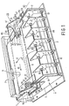
- Figure 1 is a perspective view of a preferred embodiment of the device according to the invention,
- Figure 2 is a diagrammatic plan view of the device shown in Figure 1,
- Figure 3 is a diagrammatic cross-section of the device shown in Figure 1,
- Figure 4 shows a detail of a pivot for the coupling member used in the device shown in Figures 1 to 3,
- Figure 5 is a diagrammatic side elevation of the device shown in Figure 1,
- Figure 6 is a diagrammatic plan view of an alternative embodiment of the device according to the invention,
- Figure 7 is a diagrammatic cross-section of the device shown in Figure 6,
- Figure 8 is a diagrammatic side elevation of the device shown in Figure 6.
- The device shown in Figure 1 is a device for transporting strip-shaped information carriers (for example paper strips) and is preferably used in so-called writing recording devices and printing devices. In recording devices, a possibility is the automatic recording of measurement results, but also the display of graphs, diagrams and images visible on a monitor. For recording and displaying, use is made of writing pins. In printing devices (printers), a possibility resides in matrix printers having impact members or thermal printing members, optical printers having a photo-sensitive information carrier or electronic typewriters. Such printers may be computer-controlled. The device shown in Figure 1 has a
frame 1 with abottom 3 and twoparallel side walls side walls printing head 4 is guided, which is shown only diagrammatically. For the sake of clarity, the front wall and the rear wall of the transport device and the printing or writing members are not shown. In the transport device is present a plate-shaped support 9 for apaper strip 11, which is supplied from apaper supply 13. Thepaper supply 13 consists of a stack of telescopically folded paper. Theside wall 5 has secured to it a strip-shapedtransverse guide 15 for thepaper strip 11, whose plane is at right angles to the plane of thesupport 9 parallel to thebottom 3. Thetransverse guide 15 extends parallel to the transport direction of thepaper strip 11, which is indicated by an arrow 17. As a matter of course, thetransverse guide 15 may also be integrated in theside wall 5 and may constitute the upper part thereof, as is shown in Figures 2 and 3, or may form part of one of the coupling members described below. Aconsole 19 secured to theside wall 5 forms a support for a first lever-shaped coupling member 21, while aconsole 23 secured to theside wall 7 forms a support for a second lever-shaped coupling member 25. Thecoupling members - The
first coupling member 21 comprises a plate-shaped paper guide 27, which is parallel to thesupport 9, and atransverse partition wall 29 and alongitudinal partition wall 31. Bothpartition walls paper guide 27. The transverse partition wall is at right angles to the paper transport direction 17, while thelongitudinal partition wall 31 is parallel thereto. Thepaper guide 27 has secured on it aU-shaped bracket 33, in which a firstconical pressure roller 35 is rotatably journalled. Thesecond coupling member 25 comprises a plate-shaped paper guide 37 which is parallel to thesupport 9 as well as atransverse partition wall 39 and alongitudinal partition wall 41. Bothpartition walls paper guide 37. Thetransverse partition wall 39 is at right angles to the paper transport direction 17, while thelongitudinal partition wall 41 is parallel thereto. Thepaper guide 37 has secured on it aU-shaped bracket 43, in which a secondconical pressure roller 45 is rotatably journalled. The axes of rotation of theconical rollers driving rollers pressure rollers driving shaft 47 rotatably journalled in theside walls pressure rollers driving shaft 47. In thepaper guides windows pressure rollers support 9 is provided withwindows driving rollers paper strip 11 is located between thepressure rollers 35 and thecorresponding driving roller 49 and between thepressure roller 45 and thecorresponding driving roller 51. The pressure contact between thepressure rollers paper strip 11 and thedriving rollers coupling members coupling members lines tensile spring 65. Thetilting line 61 is constituted by the connection line between twopivots tilting line 63 is constituted by the connection line between twopivots identical pivots sphere section 75 which is provided with acylindrical part 77 welded in acylindrical dish 79 with anannular collar 81 of the fixedly arrangedconsoles paper guides openings 83, of which the boundary walls form a section of a conical surface. Thepaper guides openings 83 and can thus tilt about thetilting lines tensile spring 65 to thecoupling members pivots coupling members tilting lines conical rollers tilting lines spring 65 is equal to Fs, the pressure forces FL and FR of the respective conical pressure rollers satisfy the relations: -

paper strip 11 is held taut in a direction indicated in Figure 1 by an arrow 85 (at right angles to the transport direction 17), but also in that a resulting force is exerted on thepaper strip 11 in the direction of thearrow 85, which urges the longitudinal edge of thepaper strip 11 against thetransverse guide 15. Thepaper strip 11 is consequently held constantly against thetransverse guide 15 during the transport in the direction 17 so that meandering of thepaper strip 11 is prevented. Due to the fact that use is made of only onecommon spring 65 for bothpressure rollers direction 85 is also accurately defined and the risk of bulging and folding or rumpling, respectively, of thepaper strip 11 due to ar excessively large engagement force against thetransverse guide 15 is considerably reduced. It should be noted that the triangles formed by the two pivots and the centre of the relevant pressure rollers are triangles which are rotatable about the relevant tilting lines (see Figure 2). Theconical pressure rollers rollers spring 65 on thecoupling members support 9 on thepressure rollers pivots pivots pivots pivots consoles pivots pivots - Two
parallel rods side walls paper strip 11 from thestack 13 to thesupport 9. With a transport which takes place in a direction opposite to the direction 17, the paper guides 91 favour the formation of thestack 13. The paper guides 91 may be replaced by a curved plate. - By means of a
rod 95 which is rotatably journalled in thelongitudinal partition walls actuation arm 97 is secured (see Figures 2 and 3), the paper guides 27 and 37 with thepressure rollers paper strip 11 can readily be removed. Therod 95 is provided for this purpose near the lefthand and the righthand end withtongues rod 95 are in engagement withtongues coupling members rod 95, thecoupling members tilting lines 61 and 63 (see also Figure 5). By means of a cam follower (not shown further) on the laterallydisplaceable rod 95 and a cam on thecoupling members rod 95 can be locked in the position indicated by dotted lines. - The alternative embodiment of the device according to the invention shown in Figures 6, 7 and 8, which is provided as far as possible with reference numerals corresponding to those in the preceding Figures, has only one
coupling member 109 in the form of a bridge. Thebridge 109 is constituted by atransverse rod 111 which is passed through openings in theside walls arms transverse rod 111. Thearms rotatable positioning rollers bridge 109 can be moved over roller surfaces of strip-shapedconnection arms connection arms shafts side walls 5 and 7 (see Figure 6). Theconical pressure rollers rods connection arms bracket 133 secured on thebottom 3 and the strip-shaped transverse rod 111 acompression spring 135, which keeps thepositioning rollers connection arms support 9 are provided thewindows rollers conical pressure rollers rods pressure rollers side wall 5. Since thecompression spring 135 is arranged asymmetrically at a distance A from thepositioning roller 117 and at a distance B from thepositioning roller 121, where A is smaller than B, the drivingrolller 49 is subjected to a larger pressure force by thepressure roller 35 then that to which the drivingroller 51 is subjected by thepressure roller 45. When the pressure force of thespring 135 is made equal to F , the pressure forces FL and FR exerted by thepressure rollers -

- In the pressed condition of the
pressure rollers positioning rollers positioning rollers pressure rollers shaft 47 is also located in this vertical plane. The said connection lines and the said centre line are consequently shifted, projected on the horizontal plane, with respect to the connection line between therotary shafts rotatable connection arms bridge 109 with thepositioning rollers connection arms shafts 125 and 127 (compared with the position shown in Figure 6), theconnection arms shafts pressure rollers rollers paper strip 11 can then readily be removed. Figure 8 illustrates how thebridge 109 can be moved over theconnection arms positioning rollers 117 and 119 (see also Figures 6 and 7) are rotatably journalled on-stub shafts arms rotatable lever 141, each ofshafts slot 145 in theside walls lever 141 is rotatably coupled with theshafts lever 141 is a prolonged part of thearms lever 141. Upon rotation of thelevers 141 in counterclockwise direction to the position shown in Figure 8 in dotted lines, thepositioning rollers connection arms spring 135, theconnection arms shafts positioning rollers arms slot 145 whilst simultaneously rotating. It will be appreciated that thelevers 141 are held by thespring 135 in the position shown in dotted lines until they are manually returned to the vertical position. - The invention provides a transport device for writing and printing devices, in which the directional force and the pressure force are strongly independent of spring tolerances, whilst moreover component parts are saved. The said forces can be kept sufficiently accurately within the desired limits in the wide range of transport speeds (up to 2 m/sec) occurring in practice. Thus, the risk of bulging and meandering paper is considerably reduced.
- Although the invention is described with reference to a transport device for writing and printing devices, in which standard paper is used, it is not limited thereto. The invention can be used in the transport of flexible information strips both of comparatively large and small length. In the latter case, information sheets or sheet-like information strips are concerned. Due to the fact that the transport device ensures that a longitudinal edge of the information carrier engages thesaid transverse guide, the beginning of printing or writing information always occurs at a defined area of the information carrier. Theinformation carrier may be constituted by the conventional paper or by multi-layer strips with, for example, a dielectric layer, a heat-sensitive layer or a pressure-sensitive layer for electrostatic, thermal or impact printing arrangements. In the case of thermal printing devices, the heat transfer to the information carrier can be obtained by means of a so-called thermal printing head or laser printing head. Printing devices, in which ink drops are used, are also included. It will be appreciated that the term "flexible strip" does not include those strips in which the magnetization of a layer is varied by a magnetic printing head. Furthermore, those flexible strips should be excluded which are provided for the manufacture of clothing or . fabrics with a print or a pattern. However, flexible strips, such as credit cards and other official documents, which are provided with a print or a pattern, are also included. In general, it may be said that the printed strip has to comprise information or data, although, as already stated, this strip is not of magnetic nature.
Claims (4)
Applications Claiming Priority (2)
| Application Number | Priority Date | Filing Date | Title |
|---|---|---|---|
| NL8403725A NL8403725A (en) | 1984-12-07 | 1984-12-07 | Device for transporting a flexible strip. |
| NL8403725 | 1984-12-07 |
Publications (2)
| Publication Number | Publication Date |
|---|---|
| EP0184263A1 true EP0184263A1 (en) | 1986-06-11 |
| EP0184263B1 EP0184263B1 (en) | 1989-10-11 |
Family
ID=19844876
Family Applications (1)
| Application Number | Title | Priority Date | Filing Date |
|---|---|---|---|
| EP85201980A Expired EP0184263B1 (en) | 1984-12-07 | 1985-11-27 | Device for transporting a flexible strip |
Country Status (6)
| Country | Link |
|---|---|
| US (1) | US4629177A (en) |
| EP (1) | EP0184263B1 (en) |
| JP (1) | JPS61145056A (en) |
| CA (1) | CA1257882A (en) |
| DE (1) | DE3573562D1 (en) |
| NL (1) | NL8403725A (en) |
Cited By (3)
| Publication number | Priority date | Publication date | Assignee | Title |
|---|---|---|---|---|
| DE9000255U1 (en) * | 1990-01-11 | 1991-05-16 | Siemens Nixdorf Informationssysteme Ag, 4790 Paderborn, De | |
| EP0485786A1 (en) * | 1990-10-26 | 1992-05-20 | Canon Kabushiki Kaisha | Sheet feeding apparatus |
| US5284333A (en) * | 1990-10-26 | 1994-02-08 | Canon Kabushiki Kaisha | Sheet feeding apparatus |
Families Citing this family (12)
| Publication number | Priority date | Publication date | Assignee | Title |
|---|---|---|---|---|
| FR2593157B1 (en) * | 1986-01-17 | 1988-11-04 | Benson Sa | PRESSURE ROLLER DEVICE FOR A SYSTEM FOR DRIVING A PRINTING MEDIUM ON A PRINTING MACHINE. |
| EP0419185B1 (en) * | 1989-09-18 | 1999-03-31 | Canon Kabushiki Kaisha | Conveying rotational member for an ink recording apparatus |
| US5324022A (en) * | 1992-11-16 | 1994-06-28 | Eastman Kodak Company | Tandem frusto-conical roller mechanism for receiver member edge registration |
| US5460457A (en) * | 1993-02-01 | 1995-10-24 | Eastman Kodak Company | Thermal printer having tapered rollers to maintain receiver alignment |
| US5368403A (en) * | 1993-04-30 | 1994-11-29 | Hewlett-Packard Company | Carriage support system for computer driven printer |
| DE69504263T2 (en) * | 1994-09-22 | 1999-04-08 | Eastman Kodak Co | Apparatus and method for assembling random arrangements of sheets into ordered stacks |
| KR200301930Y1 (en) * | 1997-11-20 | 2003-06-09 | 삼성전자 주식회사 | Paper image guide device for printer |
| US6269995B1 (en) | 1998-04-29 | 2001-08-07 | Gerber Scientific Products, Inc. | Friction drive apparatus for strip material |
| US6052144A (en) * | 1998-06-01 | 2000-04-18 | Eastman Kodak Company | Image printing |
| US6283655B1 (en) | 1998-06-30 | 2001-09-04 | Gerber Scientific Products, Inc. | Friction-feed plotter with laterally-movable drive roller, and related method for plotting on sheets of different widths |
| US6637634B1 (en) | 1998-12-21 | 2003-10-28 | Gerber Scientific Products, Inc. | Methods for calibration and automatic alignment in friction drive apparatus |
| US6202954B1 (en) | 1999-04-20 | 2001-03-20 | Datamax Corporation | Media tracking guide |
Citations (2)
| Publication number | Priority date | Publication date | Assignee | Title |
|---|---|---|---|---|
| DE1803860A1 (en) * | 1968-10-18 | 1970-05-27 | Kalle Ag | Method and device for spreading material webs |
| EP0102022A2 (en) * | 1982-08-30 | 1984-03-07 | HONEYWELL BULL ITALIA S.p.A. | Printing form stretching device in a printer |
Family Cites Families (3)
| Publication number | Priority date | Publication date | Assignee | Title |
|---|---|---|---|---|
| US2071682A (en) * | 1936-05-20 | 1937-02-23 | American Sheet & Tin Plate | Apparatus for guiding and aligning strip material |
| US2801102A (en) * | 1951-08-20 | 1957-07-30 | Monforts Fa A | Guiding arrangement for webs, comprising two movable pairs of rollers |
| US4068789A (en) * | 1975-10-24 | 1978-01-17 | Young Engineering, Inc. | Method and apparatus for controlling a moving web |
-
1984
- 1984-12-07 NL NL8403725A patent/NL8403725A/en not_active Application Discontinuation
-
1985
- 1985-11-27 DE DE8585201980T patent/DE3573562D1/en not_active Expired
- 1985-11-27 EP EP85201980A patent/EP0184263B1/en not_active Expired
- 1985-12-05 JP JP60272624A patent/JPS61145056A/en active Granted
- 1985-12-05 CA CA000496953A patent/CA1257882A/en not_active Expired
- 1985-12-26 US US06/814,576 patent/US4629177A/en not_active Expired - Fee Related
Patent Citations (2)
| Publication number | Priority date | Publication date | Assignee | Title |
|---|---|---|---|---|
| DE1803860A1 (en) * | 1968-10-18 | 1970-05-27 | Kalle Ag | Method and device for spreading material webs |
| EP0102022A2 (en) * | 1982-08-30 | 1984-03-07 | HONEYWELL BULL ITALIA S.p.A. | Printing form stretching device in a printer |
Non-Patent Citations (1)
| Title |
|---|
| HEWLETT-PACKARD JOURNAL, vol. 33, no. 12, December 1982, pages 28-33; R.M. KEMPLIN et al.: "Graphics plotter mechanical design for performance and reliability at low cost" * |
Cited By (3)
| Publication number | Priority date | Publication date | Assignee | Title |
|---|---|---|---|---|
| DE9000255U1 (en) * | 1990-01-11 | 1991-05-16 | Siemens Nixdorf Informationssysteme Ag, 4790 Paderborn, De | |
| EP0485786A1 (en) * | 1990-10-26 | 1992-05-20 | Canon Kabushiki Kaisha | Sheet feeding apparatus |
| US5284333A (en) * | 1990-10-26 | 1994-02-08 | Canon Kabushiki Kaisha | Sheet feeding apparatus |
Also Published As
| Publication number | Publication date |
|---|---|
| JPH0578499B2 (en) | 1993-10-28 |
| EP0184263B1 (en) | 1989-10-11 |
| CA1257882A (en) | 1989-07-25 |
| DE3573562D1 (en) | 1989-11-16 |
| US4629177A (en) | 1986-12-16 |
| JPS61145056A (en) | 1986-07-02 |
| NL8403725A (en) | 1986-07-01 |
Similar Documents
| Publication | Publication Date | Title |
|---|---|---|
| EP0184263B1 (en) | Device for transporting a flexible strip | |
| US5634729A (en) | Magnetic reader with a flexible pressure film pressure pad | |
| US5762431A (en) | Thermal printer and method for using | |
| EP0595321B1 (en) | Sheet convey apparatus | |
| EP0063590B1 (en) | Selective paper insertion and feeding means for individual sheet printing apparatus | |
| JPS6099692A (en) | Ink ribbon cassette supporting device | |
| US4956662A (en) | Apparatus for and method of recording color picture image | |
| EP1018435A2 (en) | Printer with floating print head | |
| US5795087A (en) | Pivoting roller for skewless document feed | |
| CN108068475A (en) | Recording device | |
| KR0132862B1 (en) | Apparatus & method guiding paper for a printer | |
| EP0384631B1 (en) | Transport device | |
| US5405205A (en) | Sheet medium transport system, particularly for printers and plotters | |
| US6239825B1 (en) | Thermal printing apparatus | |
| USRE38473E1 (en) | Printer with floating print head with alignment surfaces to position printhead | |
| US4813780A (en) | Image mask for microfilm roll handler | |
| JP2713778B2 (en) | Airline boarding pass issuing machine | |
| KR100533409B1 (en) | Print unit and a printer using the same | |
| IE69331B1 (en) | A Printer | |
| EP1652681B1 (en) | Image recording apparatus and sheet material transporting apparatus | |
| JP4334400B2 (en) | Intermediate transfer type thermal transfer printer | |
| WO1992018948A1 (en) | Dot-matrix printer | |
| JP3691324B2 (en) | Double thermal printer | |
| US3199444A (en) | Coded tag printer using punched tags | |
| JP3616479B2 (en) | Ticket issuing device |
Legal Events
| Date | Code | Title | Description |
|---|---|---|---|
| PUAI | Public reference made under article 153(3) epc to a published international application that has entered the european phase |
Free format text: ORIGINAL CODE: 0009012 |
|
| AK | Designated contracting states |
Kind code of ref document: A1 Designated state(s): DE FR GB IT NL SE |
|
| 17P | Request for examination filed |
Effective date: 19861204 |
|
| 17Q | First examination report despatched |
Effective date: 19880414 |
|
| GRAA | (expected) grant |
Free format text: ORIGINAL CODE: 0009210 |
|
| AK | Designated contracting states |
Kind code of ref document: B1 Designated state(s): DE FR GB IT NL SE |
|
| REF | Corresponds to: |
Ref document number: 3573562 Country of ref document: DE Date of ref document: 19891116 |
|
| ITF | It: translation for a ep patent filed |
Owner name: ING. C. GREGORJ S.P.A. |
|
| ET | Fr: translation filed | ||
| PLBE | No opposition filed within time limit |
Free format text: ORIGINAL CODE: 0009261 |
|
| STAA | Information on the status of an ep patent application or granted ep patent |
Free format text: STATUS: NO OPPOSITION FILED WITHIN TIME LIMIT |
|
| 26N | No opposition filed | ||
| PGFP | Annual fee paid to national office [announced via postgrant information from national office to epo] |
Ref country code: GB Payment date: 19921105 Year of fee payment: 8 |
|
| PGFP | Annual fee paid to national office [announced via postgrant information from national office to epo] |
Ref country code: FR Payment date: 19921120 Year of fee payment: 8 |
|
| PGFP | Annual fee paid to national office [announced via postgrant information from national office to epo] |
Ref country code: SE Payment date: 19921126 Year of fee payment: 8 |
|
| ITTA | It: last paid annual fee | ||
| PGFP | Annual fee paid to national office [announced via postgrant information from national office to epo] |
Ref country code: NL Payment date: 19921130 Year of fee payment: 8 |
|
| PGFP | Annual fee paid to national office [announced via postgrant information from national office to epo] |
Ref country code: DE Payment date: 19930128 Year of fee payment: 8 |
|
| PG25 | Lapsed in a contracting state [announced via postgrant information from national office to epo] |
Ref country code: GB Effective date: 19931127 |
|
| PG25 | Lapsed in a contracting state [announced via postgrant information from national office to epo] |
Ref country code: SE Effective date: 19931128 |
|
| PG25 | Lapsed in a contracting state [announced via postgrant information from national office to epo] |
Ref country code: NL Effective date: 19940601 |
|
| NLV4 | Nl: lapsed or anulled due to non-payment of the annual fee | ||
| GBPC | Gb: european patent ceased through non-payment of renewal fee |
Effective date: 19931127 |
|
| PG25 | Lapsed in a contracting state [announced via postgrant information from national office to epo] |
Ref country code: FR Effective date: 19940729 |
|
| PG25 | Lapsed in a contracting state [announced via postgrant information from national office to epo] |
Ref country code: DE Effective date: 19940802 |
|
| REG | Reference to a national code |
Ref country code: FR Ref legal event code: ST |
|
| EUG | Se: european patent has lapsed |
Ref document number: 85201980.1 Effective date: 19940610 |