EP0184013A2 - Method for the measurement of hydrostatic and gas pressure in a sealed bore hole - Google Patents
Method for the measurement of hydrostatic and gas pressure in a sealed bore hole Download PDFInfo
- Publication number
- EP0184013A2 EP0184013A2 EP85114119A EP85114119A EP0184013A2 EP 0184013 A2 EP0184013 A2 EP 0184013A2 EP 85114119 A EP85114119 A EP 85114119A EP 85114119 A EP85114119 A EP 85114119A EP 0184013 A2 EP0184013 A2 EP 0184013A2
- Authority
- EP
- European Patent Office
- Prior art keywords
- measuring
- probe
- pressure
- measuring tube
- tube
- Prior art date
- Legal status (The legal status is an assumption and is not a legal conclusion. Google has not performed a legal analysis and makes no representation as to the accuracy of the status listed.)
- Granted
Links
- 238000005259 measurement Methods 0.000 title claims abstract description 14
- 238000000034 method Methods 0.000 title claims description 9
- 230000002706 hydrostatic effect Effects 0.000 title 1
- 239000000523 sample Substances 0.000 claims abstract description 64
- 238000009530 blood pressure measurement Methods 0.000 claims abstract description 9
- 239000007788 liquid Substances 0.000 claims abstract description 4
- 238000007789 sealing Methods 0.000 claims description 15
- 239000012528 membrane Substances 0.000 claims description 14
- 230000005540 biological transmission Effects 0.000 claims description 10
- 238000005452 bending Methods 0.000 claims description 7
- 230000006835 compression Effects 0.000 claims description 6
- 238000007906 compression Methods 0.000 claims description 6
- 238000013461 design Methods 0.000 description 4
- 239000007789 gas Substances 0.000 description 3
- 239000007787 solid Substances 0.000 description 3
- 239000011083 cement mortar Substances 0.000 description 2
- 239000004744 fabric Substances 0.000 description 2
- 238000013022 venting Methods 0.000 description 2
- XLYOFNOQVPJJNP-UHFFFAOYSA-N water Substances O XLYOFNOQVPJJNP-UHFFFAOYSA-N 0.000 description 2
- 238000004026 adhesive bonding Methods 0.000 description 1
- 238000010276 construction Methods 0.000 description 1
- 238000010586 diagram Methods 0.000 description 1
- 230000009969 flowable effect Effects 0.000 description 1
- 239000003673 groundwater Substances 0.000 description 1
- 238000011835 investigation Methods 0.000 description 1
- 239000000463 material Substances 0.000 description 1
- 239000002245 particle Substances 0.000 description 1
- 230000000149 penetrating effect Effects 0.000 description 1
- 230000036316 preload Effects 0.000 description 1
- 238000003825 pressing Methods 0.000 description 1
- 230000001681 protective effect Effects 0.000 description 1
- 230000003313 weakening effect Effects 0.000 description 1
Images


Classifications
-
- E—FIXED CONSTRUCTIONS
- E21—EARTH OR ROCK DRILLING; MINING
- E21B—EARTH OR ROCK DRILLING; OBTAINING OIL, GAS, WATER, SOLUBLE OR MELTABLE MATERIALS OR A SLURRY OF MINERALS FROM WELLS
- E21B33/00—Sealing or packing boreholes or wells
- E21B33/10—Sealing or packing boreholes or wells in the borehole
- E21B33/12—Packers; Plugs
- E21B33/124—Units with longitudinally-spaced plugs for isolating the intermediate space
-
- E—FIXED CONSTRUCTIONS
- E21—EARTH OR ROCK DRILLING; MINING
- E21B—EARTH OR ROCK DRILLING; OBTAINING OIL, GAS, WATER, SOLUBLE OR MELTABLE MATERIALS OR A SLURRY OF MINERALS FROM WELLS
- E21B47/00—Survey of boreholes or wells
- E21B47/06—Measuring temperature or pressure
-
- E—FIXED CONSTRUCTIONS
- E21—EARTH OR ROCK DRILLING; MINING
- E21B—EARTH OR ROCK DRILLING; OBTAINING OIL, GAS, WATER, SOLUBLE OR MELTABLE MATERIALS OR A SLURRY OF MINERALS FROM WELLS
- E21B34/00—Valve arrangements for boreholes or wells
- E21B34/06—Valve arrangements for boreholes or wells in wells
- E21B34/14—Valve arrangements for boreholes or wells in wells operated by movement of tools, e.g. sleeve valves operated by pistons or wire line tools
Definitions
- the invention relates to a method for measuring liquid and gas pressure in a sealed borehole by means of a measuring tube introduced into the borehole, predetermined areas of the borehole, in which the pressure measurement is to be carried out, against each other through to the respective intended area between the outer wall of the measuring tube and sealing means provided on the borehole wall and the measurement is carried out by means of a measuring probe, the part designed for the measurement reaches a measuring point provided in the wall of the measuring tube, as well as a measuring tube for carrying out the method and a measuring probe for the measuring tube.
- the pressure is measured by establishing a connection to an interior of the measuring probe via a valve provided in the measuring tube wall, which is opened by the measuring probe, in which the measurement takes place.
- the object of the invention is to enable pressure measurement with high accuracy to avoid the disadvantages of the known method without the medium to be measured penetrating into the measuring tube. This object is achieved on the basis of the features of patent claim 1, by a measuring tube for carrying out the method according to patent claim 2 and by a measuring probe for this measuring tube according to patent claim 10.
- the measuring tube 1 consists of individual tube pieces 2 and tube sleeves 3 connecting them to one another, so that it can be done by continuously joining tube sleeves and tube pieces and thereby pushing them further into the borehole 4 to a desired length with a corresponding number of measuring points provided in the tube sleeves 5 can be put together.
- a sealing sleeve 6 is attached on the outside of the pipe section.
- the sealing sleeves 6 of the measuring tube are connected to one another by a filling line (not shown) in order to pressurize them by means of a supplied flowable medium, such as gas, water or cement mortar, so that they rest firmly and thus sealingly on the wall 7 of the borehole.
- a supplied flowable medium such as gas, water or cement mortar
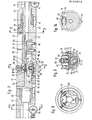
- the individual pipe sections 2 and the pipe sleeves 3 have guide grooves 12 for guiding the wheels 10, 11 of a measuring probe shown in FIGS. 4 to 12, which run parallel to the axis of the measuring pipe 1 and have an angular distance of 120 from one another. So that the guide grooves 12 of the pipe pieces and pipe sleeves can merge into one another, the pipe sleeves and pipe pieces are to be mounted in a predetermined angular position, for which purpose a positive engagement between them is provided, as in the example 2 shown by extensions 13, 14 which engage in a correspondingly shaped recess 15, 16 of the other part.
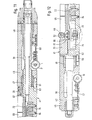
- a threaded hole 22 is provided in the pipe socket 3, into which the threaded connector 23 of the housing 24 of the measuring cell 25 is screwed.
- An O-ring 26 inserted between the measuring cell housing 24 and the pipe sleeve 3 ensures the sealing of the measuring tube.
- a pressure pick-up element designed as a piston 27 is movably mounted, in which the piston shaft 28 is guided in an axial ball bearing 29 in the threaded connector 23.
- the interior of the housing 24 receiving the piston 27 is outward, ie opposite the space 9, in which the pressure to be measured is present, sealed by a thin, highly elastic membrane 30.
- the outer end face of the piston 27 bears against this membrane or is fastened to it, for example by gluing.
- the pressure acting on the membrane 30 is thus transmitted to the piston 27, so that its underside comes into contact with the inner shoulder 32 of the housing 24. Only a very small piston travel 33 is required for the pressure measurement.
- a protective filter protection plate 35 which is inserted in the housing cover 36 which fastens the membrane 30 to the housing 24.
- the unit consisting of piston 27 and membrane 30 is preloaded in the direction of the interior of the measuring tube by a compression spring 31.
- the pressure acting on the inside of the membrane 30 is compensated by this compression spring.
- the compression spring is clamped, for example as shown, between the filter plate 35 and a cover plate 34 abutting the membrane 30.
- the compression spring 31 can be dispensed with for overpressure measurements.
- the free end of the piston shaft 28 projects a small amount into the interior of the measuring tube 3 and has a rounded tip 38 which is intended for the mechanical measuring contact with the measuring probe 40 described in more detail below.
- the measuring probe 40 forms an elongated, cylindrical one Body with a central part 41 which is relative to the longitudinal axis of the measuring probe the end parts 42, 43 guided by the wheels 10, 11 can be rotated.
- the parts 41, 42, 43 are supported relative to one another by plain bearing pairs 45, 46 and 47, 48, which are each provided on the two outer ends of the probe end parts 42, 43 and support elongated axle shafts 50, 51, which are located on both outer ends of the middle Probe part 41 are integrally formed.
- the axle shaft 51 enclosed by the front end part 43 of the measuring probe simultaneously forms the actuating rod for rotating the central probe part 41 in the measuring position or out of the measuring position and is drilled along its length so that it can accommodate connecting cables (not shown) to the measuring device provided in the central probe part.
- the rotary movement takes place, for example, through an angle of 45 ° between the positions shown in FIGS. 5 and 6.
- Can be the previously mentioned stop cam 20 of the measuring tube are each arranged on both sides to the guide grooves 12, so that the measuring probe un g e-stops in the measuring tube 1 moves when the central probe portion of the driving position shown in Figure 5 occupies in Fig.. If the measuring wheel of the measuring device 54 of the piston of the measuring cell with the angular distance of 45 ° passes laterally 53, the tip 38, and have accordingly the counter-stops 55, the stop cam 20 passes the measuring tube, the average probe portion 41 by 45 0 in FIG. 6 The angular position shown is rotated and the probe is retracted until the counter stops 55 come into exact contact with the stop cams 20, as the diagram in FIG. 4 shows schematically.
- the exact contact with the stop cams 20 and thus the exact alignment of the measuring probe 40 to the measuring tube 1 is ensured by the spherical design of the surface of the counter-stops 55 and the conical design of the surface of the stop cams 20.
- the guide wheels 10, 11 of the measuring probe also contribute to a precise alignment, those with a relatively precisely set front support the measuring probe in the guide grooves 12 of the measuring tube. This spring preload is given by the mounting of the guide wheels 10, 11 shown in FIGS. 11 and 12 at the end of a leaf spring 57, 58.
- stop bolts 60, 61 which are fastened with an axially parallel course in the probe end parts 42, 43 and engage in a circumferential groove 62, 63 of the central probe part 41, the end faces of which lie opposite one another in the circumferential direction of the measuring probe, stop surfaces for the stop bolts 60, 61 form.
- the measuring wheel 53 thus moves under the crest 38 and thus pushes the piston 27 of the measuring cell 25, which forms the pressure-absorbing member, outward a small distance relative to the measuring tube, and the measuring device 54 of the measuring probe measures the force required for this or the force required to keep the piston against the outside pressure acting on it out of contact with the housing shoulder 32 of the measuring cell.
- the measuring wheel 53 is mounted on an axis 66 which is located at the end of a lever 65 is attached, which runs parallel to the longitudinal axis of the measuring probe and is pivotable about an axis 67 relative to the measuring probe.
- the pivoting range of the lever 65 is very limited, since the lever end carrying the measuring wheel 53 on a transmission member 68 of the measuring device and a stop pin 69 is provided at the opposite end of the lever 65.
- the stop bolt 69 is designed as a threaded bolt with a lock nut 70 so that the pivoting range of the lever can be adjusted radially outwards.
- the measuring device 54 is arranged in a longitudinal cutout 70 of the solid main body 71 of the central probe part 41 which is approximately square in cross section.
- This recess 70 is closed by a membrane 72, which is held by a closure body 73 on the main body 71 by means of screw bolts 74.
- the transmission member 68 forms a closed frame 75 arranged in the recess 70, which surrounds a measuring beam 76 and is fixedly connected to it by a screw bolt 77 with a lock nut 78.
- a threaded bolt 79 fastened to the outside of the frame 75 of the transmission member 68 extends through an opening in the membrane 72 and up to the end of the lever 65 supporting the measuring wheel 53, so that it moves or deflects the measuring wheel 53 on the measuring beam 76 can transmit.
- a screw nut 80 is screwed onto the threaded bolt 79 and presses a washer 81, which surrounds the screw bolt, in a sealing manner against the membrane 72, so that it is between the frame 75 and this disc
- the measuring bar 76 is fixed at one end by two screws 84, 85 to the solid main body 71 of the measuring probe, in such a way that this measuring bar end rests firmly against the recess 70 on a raised base part 86.
- the remaining part of the measuring bar for example starting from its center, is located at a short distance from a stepped bottom part 88 of the recess 70, so that it can be bent out by the measuring movement of the transmission member 68 firmly connected to it.
- the bending movement of the measuring bar is limited by an adjusting screw 89 forming a stop, which is enclosed by the screw bolt 77, which connects the measuring bar to the frame 75 of the transmission member 68.
- the end of the adjusting screw 89 comes to a stop in a bottom recess 90 of the recess 70.
- This bottom recess 90 is provided for receiving the lower part of the frame 75 surrounding the measuring bar.
- a play 91 of 0.3 mm is set by the adjusting screw 89, for example.
- the force measurement by means of the measuring bar 76 is carried out by determining its bending deformation, in that strain gauges are attached to the outside of the measuring bar in a certain area 92, the stretching of which leads to a change in an electrical resistance.
- a suitable arrangement of the strain gauges to several and their electrical connection in the form of a Wheatston bridge circuit enable high measurement accuracy.
- the area 92 of the measuring bar on which the bending movement is measured has a considerable cross-sectional weakening due to a recess 93 which extends in the longitudinal direction of the measuring bar and has an opening 94 on the outside opposite the free end 87 of the bar.
- the measuring bar thus has an inwardly directed free end 95 which runs parallel to the bending region 92.
- the frame 75 of the transmission member 68 is fastened to this free end in the manner described. Consequently, the bending deformation is transferred from this inward free end 95 to the bending area via the free outer beam end 87.
- Designated at 96 is a piece of an electrical cable leading through the axle shaft 51 to the outside, which creates the connection between the strain gauges and an electrical measuring device arranged on the outside.
- a piece of a cable 97 leading outward from the measuring probe 40 is also: indicated in Fig. 4.
- the measuring arrangement described for the force measurement can also be designed differently, in that instead of a measuring bar with strain gauges commercially available force sensors are used which, according to the ohmic capacitive, instructive or piezoelectric measuring principle, measure a measuring movement against the constant force of a spring element into an electrical one Convert measurement signal.
- Fig. 13 shows an embodiment of a sealing device 100, which compared to the use of a seal cuff 6 according to the illustration in Fig. 1 ensures a more reliable and perfect seal of the area in which the pressure measurement is to take place. This is of great importance for an accurate determination of the pressure in this area.
- the sealing device 100 consists of a pair of sleeves 103, 104 attached to the outside of the measuring tube 101 via flanges 102, which are filled by means of a filling line 105 from outside the borehole 106 with a hardening filling medium, for example cement mortar, so that they seal lay against the borehole wall 107.
- the filling medium flows into the sleeves 103, 104 via a filling valve mechanism 109, 110 clearly shown in FIG. 14.
- the valve mechanism has a rubber-elastic hose piece 114 which surrounds the return line 111 and thus a number of holes 113 provided therein, so that backflow into the return line is prevented.
- the filled sleeves 103, 104 seal a space 116 between them, which is then also filled with, for example, a hardening filling medium 117. Since the latter comes into direct contact with the possibly uneven borehole wall 107, a seal is obtained which is considerably better than the seal simply by pressing on a sleeve.
- a second filling line is for filling the space 116 119 provided with a return line 120.
- the return line has a filling valve mechanism 122, which is of the same design as that already described with reference to FIG. 14.
- the return line 120 has a venting mechanism 123, which has a fabric sleeve attached to it, which encloses a number of holes 125 in the return line 120.
- the fabric of the cuff 124 allows air and / or water to flow from the space 116 into the return line, but retains the filling medium there.
- a sealing device 100 of the type described above is provided on both sides of a measuring cell 25 ′′.
Landscapes
- Geology (AREA)
- Life Sciences & Earth Sciences (AREA)
- Engineering & Computer Science (AREA)
- Mining & Mineral Resources (AREA)
- Physics & Mathematics (AREA)
- Environmental & Geological Engineering (AREA)
- Fluid Mechanics (AREA)
- Geochemistry & Mineralogy (AREA)
- General Life Sciences & Earth Sciences (AREA)
- Geophysics (AREA)
- Measuring Fluid Pressure (AREA)
- Examining Or Testing Airtightness (AREA)
- Infusion, Injection, And Reservoir Apparatuses (AREA)
- Pens And Brushes (AREA)
Abstract
Für die Messung von Flüssigkeits- und Gasdruck im Untergrund ist in ein Bohrloch ein Messrohr (1) eingesetzt und zur Abgrenzung von Bereichen, in denen die Druckmessung erfolgen soll, gegenüber der Bohrlochwand abgedichtet. In jedem dieser Bereiche ist in die Messrohrwand eine Messzelle (25) eingesetz, die ein bewegliches Druckaufnahmeorgan einschliesst, auf das der Druck des das Messrohr umgebenden Mediums wirkt. Ein Ende (38) des Druckaufnahmeorgans ragt in den Innenraum des Messrohres hinein und wird zum Messen vom Messrad (53) einer Messonde (40) unterfahren, so dass das Druckaufnahmeorgan entgegen dem auf ihn wirkenden Druck radial nach aussen bewegt wird. Die hierbei auf das Messrad (53) wirkende Kraft wird durch eine Messeinrichtung (54) für die Druckmessung ermittelt. Da die Messzelle (25) dicht in die Messrohrwand eingesetzt ist, dringt das zu messende Medium nicht in das Messrohr ein. Das Messrad (53) wird durch Verdrehen eines mittleren Teiles (41) der Messonde (40) relativ zu den auf Rädern (10, 11) geführten Endteilen (42, 43) der Messonde und ihr Heranfahren bis zu einem Kontakt von Anschlägen (55, 20) mit hoher Genauigkeit in Messposition gebracht, wie es Voraussetzung für eine hohe Präzision der Druckmessung ist.A measuring tube (1) is inserted into a borehole for measuring liquid and gas pressure in the subsurface and is sealed off from the borehole wall to delimit areas in which the pressure measurement is to take place. In each of these areas, a measuring cell (25) is inserted into the measuring tube wall, which includes a movable pressure-receiving element, on which the pressure of the medium surrounding the measuring tube acts. One end (38) of the pressure pick-up element protrudes into the interior of the measuring tube and is passed under the measuring wheel (53) of a measuring probe (40) for measurement, so that the pressure pick-up element is moved radially outward against the pressure acting on it. The force acting on the measuring wheel (53) is determined by a measuring device (54) for the pressure measurement. Since the measuring cell (25) is inserted tightly into the measuring tube wall, the medium to be measured does not penetrate the measuring tube. The measuring wheel (53) is turned by rotating a central part (41) of the measuring probe (40) relative to the end parts (42, 43) of the measuring probe guided on wheels (10, 11) and moving it up to a contact of stops (55, 20) brought into the measuring position with high accuracy, as is a prerequisite for high precision of the pressure measurement.
Description
Die Erfindung betrifft ein Verfahren zur Messung von Flüssigkeits- und Gasdruck in einem abgedichteten Bohrloch mittels eines in das Bohrloch eingebrachten Messrohres, wobei vorgegebene Bereiche des Bohrloches, in denen die Druckmessung erfolgen soll, gegeneinander durch beidseitig zu dem jeweiligen vorgesehenen Bereich zwischen der Aussenwand des Messrohres und der Bohrlochwand vorgesehene Dichtungseinrichtungen abgedichtet werden und die Messung mittels einer Messonde erfolgt, deren für die Messung ausgebildeter Teil an eine in der Wand des Messrohres vorgesehene Messstelle gelangt, sowie ein Messrohr zur Durchführung des Verfahrens und eine Messonde für das Messrohr.The invention relates to a method for measuring liquid and gas pressure in a sealed borehole by means of a measuring tube introduced into the borehole, predetermined areas of the borehole, in which the pressure measurement is to be carried out, against each other through to the respective intended area between the outer wall of the measuring tube and sealing means provided on the borehole wall and the measurement is carried out by means of a measuring probe, the part designed for the measurement reaches a measuring point provided in the wall of the measuring tube, as well as a measuring tube for carrying out the method and a measuring probe for the measuring tube.
Ein Verfahren dieser Art ist bekannt durch die US-Patentschriften 4 192 181 und 4 230 180. Die Druckmessung erfolgt beispielsweise für geophysikalische Untersuchungen, z.B. für den Tunnelbau, für Untersuchungen des Untergrundes an Staudämmen oder anderen Bauwerken oder auch zur Ermittlung von Grundwasserabsenkungen.A method of this kind is known from US Pat. Nos. 4,192,181 and 4,230,180. for tunnel construction, for investigations of the subsoil at dams or other structures or for the determination of groundwater subsidence.
Nach dem vorbekannten Verfahren erfolgt die Druckmessung, indem über ein in der Messrohrwand vorgesehenes Ventil, das durch die Messonde geöffnet wird, eine Verbindung mit einem Innenraum der Messonde hergestellt wird, in dem die Messung erfolgt. Durch das Ueberleiten des zu messenden Mediums in der Messonde können sich Druckveränderungen ergeben, die zu einem fehlerhaften Ergebnis führen, ausserdem können dabei Feststoffpartikel zu Störungen an dem hierbei verwendeten Ventilmechanismus führen.According to the previously known method, the pressure is measured by establishing a connection to an interior of the measuring probe via a valve provided in the measuring tube wall, which is opened by the measuring probe, in which the measurement takes place. By transferring the to be measured Medium in the measuring probe can result in pressure changes which lead to a faulty result, moreover, solid particles can lead to faults in the valve mechanism used here.
Der Erfindung liegt die Aufgabe zugrunde, zur Vermeidung der Nachteile des bekannten Verfahrens eine Druckmessung mit hoher Genauigkeit zu ermöglichen, ohne dass das zu messende Medium in das Messrohr eindringt. Die Lösung dieser Aufgabe erfolgt aufgrund der Merkmale des Patentanspruches 1, durch ein Messrohr zur Durchführung des Verfahrens gemäss Patentanspruch 2 sowie durch eine Messsonde für dieses Messrohr gemäss Patentanspruch 10.The object of the invention is to enable pressure measurement with high accuracy to avoid the disadvantages of the known method without the medium to be measured penetrating into the measuring tube. This object is achieved on the basis of the features of
Im folgenden wird die Erfindung anhand eines in den Zeichnungen dargestellten Ausführungsbeispieles näher erläutert. Es zeigt:
- Fig. 1 eine schematische Darstellung eines Teils des in einem Bohrloch montierten Messrohres in Axialschnitt,
- Fig. 2 einen Axialschnitt durch das Messrohr nach - Fig. 1 im Bereich einer Messstelle,
- Fig. 3 einen Querschnitt durch eine Messzelle des Messrohres nach Fig. 1 in vergrösserter Darstellung relativ zu den Darstellungen der Fig. 1 und 2,
- Fig. 4 eine Seitenansicht einer Messonde in schematischer Darstellung mit einem Teil des Messrohres,
- Fig. 5 einen Querschnitt durch die Messonde nach Fig. 1 in Fahrposition relativ zu dem Messrohr,
- Fig. 6 einen Querschnitt durch die Messonde in Messposition,
- Fig. 7 einen Axialschnitt durch den mittleren Bereich einer Messonde,
- Fig. 8 einen Querschnitt entlang der Linie VIII-VIII in Fig. 7,
- Fig. 9 einen Querschnitt entlang der Linie IX-IX der Fig. 7,
- Fig. 10 einen Querschnitt entlang der Linie X-X der Fig. 7,
- Fig. 11 einen axialen Teilquerschnitt der Messonde mit ihrem hinteren Ende,
- Fig. 12 einen axialen Teilschnitt durch die Messonde mit ihrem vorderen Ende,
- Fig. 13 eine schematische Darstellung eines Teiles eines in einem Bohrloch montierten Messrohres mit einer Dichteinrichtung,
- Fig. 14 einen Querschnitt durch einen Füllventilmechanismus und
- Fig. 15 einen Querschnitt durch einen Entlüftungsmechanismus.
- 1 is a schematic representation of a part of the measuring tube mounted in a borehole in axial section,
- 2 shows an axial section through the measuring tube according to FIG. 1 in the area of a measuring point,
- 3 shows a cross section through a measuring cell of the measuring tube according to FIG. 1 in an enlarged representation relative to the representations of FIGS. 1 and 2,
- Fig. 4 is a side view of a measuring probe in cal mathematical representation with part of the measuring tube,
- 5 shows a cross section through the measuring probe according to FIG. 1 in the driving position relative to the measuring tube,
- 6 shows a cross section through the measuring probe in the measuring position,
- 7 shows an axial section through the central region of a measuring probe,
- 8 shows a cross section along the line VIII-VIII in FIG. 7,
- 9 is a cross section along the line IX-IX of FIG. 7,
- 10 is a cross section along the line XX of FIG. 7,
- 11 shows an axial partial cross section of the measuring probe with its rear end,
- 12 shows an axial partial section through the measuring probe with its front end,
- 13 is a schematic representation of a part of a measuring tube mounted in a borehole with a sealing device,
- 14 shows a cross section through a filling valve mechanism and
- 15 shows a cross section through a venting mechanism.
Das Messrohr 1 besteht aus einzelnen aneinandergesetzten Rohrstücken 2 und diese miteinander verbindenden Rohrmuffen 3, so dass es sich durch.fortlaufendes Aneinanderfügen von Rohrmuffen und Rohrstücken und dabei weiteres Einschieben in das Bohrloch 4 auf eine gewünschte Länge mit einer entsprechenden Anzahl von in den Rohrmuffen vorgesehenen Messstellen 5 zusammensetzen lässt. An der Aussenseite des Rohrstückes ist auf nicht näher dargestellte Weise eine Dichtmanschette 6 befestigt. Die Dichtmanschetten 6 des Messrohres sind durch eine nicht dargestellte Fülleitung miteinander verbunden, um sie mittels eines zugeführten strömungsfähigen Mediums, wie Gas, Wasser oder Zementmörtel unter Druck zu setzen, so dass sie sich fest und damit dichtend an die Wand 7 des Bohrloches anlegen. Auf diese Weise ist jede Messstelle zwischen zwei Dichtmanschetten 6 eingeschlossen, so dass an ihr der in diesem eingeschlossenen Bereich vorhandene Druck gemessen werden kann. Dieser Druck kann durch Gas oder Flüssigkeit gebildet sein, die aus dem umgebenden Material 8 in den Raum 9 zwischen dem Messrohr 1 und der Bohrlochwand 7 eingedrungen sind.The measuring
Die einzelnen Rohrstücke 2 und die Rohrmuffen 3 haben für die Führung der Räder 10, 11 einer in den Fig. 4 - 12 dargestellten Messonde Führungsrillen 12, die achsparallel zu dem Messrohr 1 verlaufen und einen Winkelabstand von 120 zueinander aufweisen. Damit die Führungsrillen 12 der Rohrstücke und Rohrmuffen ineinander übergehen können, sind die Rohrmuffen und Rohrstücke in vorgegebener Winkelposition zueinander zu montieren, wofür ein formschlüssiger Eingriff zwischen ihnen vorgesehen ist, wie im Beispiel nach Fig. 2 durch Fortsätze 13, 14 gezeigt, die in eine entsprechend geformte Aussparung 15, 16 des anderen Teiles eingreifen. Es versteht sich, dass eine solche formschlüssige Verbindung auf verschiedene Weise erfolgen kann, ebenso wie die Sicherung der Lage der Teile zueinander in axialer Richtung durch radial oder tangential verlaufende Schrauben oder Bolzen, die sich durch beide miteinander zu verbindende Teile erstrecken. Die Verbindung hat jedoch so zu erfolgen, dass das Messrohr gas-oder flüssigkeitsdicht ist. Entsprechend Fig. 2 ist in einer Umfangsnut der Rohrstücke 2 ein O-Ring 18 eingelegt, so dass die das Rohrstück 2 umfassende Rohrmuffe 3 mit ihrer Innenwand an dem O-Ring dicht anliegt. An der Innenseite der Rohrmuffe 3 sind ausserdem angrenzend an jede Führungsrille 12 Anschlagnocken 20 vorgesehen, die für die genaue Positionierung der Messonde in Messposition dienen, wie im folgenden noch näher beschrieben wird.The
An der Messstelle 5 ist in der Rohrmuffe 3 ein Gewindeloch 22 vorgesehen, in das der Gewindestutzen 23 des Gehäuses 24 der Messzelle 25 eingeschraubt ist. Ein zwischen das Messzellengehäuse 24 und die Rohrmuffe 3 eingelegter O-Ring 26 gewährleistet die Abdichtung des Messrohres.At the
In der Messzelle 25 ist ein als Kolben 27 ausgeführtes Druckaufnahmeorgan beweglich gelagert, in dem der Kolbenschaft 28 in einem Axialkugellager 29 in dem Gewindestutzen 23 geführt ist. Der den Kolben 27 aufnehmende Innenraum des Gehäuses 24 ist nach aussen, d.h. gegenüber dem Raum 9, in dem der zu messende Druck vorhanden ist, durch eine dünne, hochelastische Membran 30 abgedichtet. An dieser Membran liegt die äussere Stirnfläche des Kolbens 27 an oder ist an ihr, z.B. durch Kleben, befestigt. Der auf die Membran 30 wirkende Druck wird somit auf den Kolben 27 übertragen, so dass seine Unterseite an der Innenschulter 32 des Gehäuses 24 auf Anlage gelangt. Für die Druckmessung ist nur ein sehr geringer Kolbenweg 33 erforderlich. Mit geringem Abstand von der Membran 30 ist diese von einer schützenden Filter-Schutzplatte 35 überdeckt, die in dem die Membran 30 am Gehäuse 24 befestigenden Gehäusedeckel 36 eingesetzt ist. Ur durch die Messung von äusserem Unterdruck relativ zu dem innerhalb des Messrohres vorhandenen Druck, d.h. normalerweise Atmosphärendruck, zu ermöglichen, ist die Einheit aus Kolben 27 und Membran 30 in Richtung zum Innenraum des Messrohres durch eine Druckfeder 31 vorbelastet. Durch diese Druckfeder wird der auf die Innenseite der Membran 30 wirkende Druck kompensiert. Die Druckfeder ist beispielsweise entsprechend der Darstellung zwischen der Filterplatte 35 und einer an der Membran 30 anliegenden Deckplatte 34 eingespannt. Für Ueberdruckmessungen kann auf die Druckfeder 31 verzichtet werden.In the measuring
Das freie Ende des Kolbenschaftes 28 ragt um ein geringes Mass in den Innenraum des Messrohres 3 hinein und weist eine abgerundete Kuppe 38 auf, die bestimmt ist für den mechanischen Messkontakt mit der im folgenden näher beschriebenen Messonde 40. Die Messonde 40 bildet einen langgestreckten, zylindrischen Körper mit einem mittleren Teil 41, der um die Längsachse der Messonde relativ zu den durch die Räder 10, 11 geführten Endteilen 42, 43 verdrehbar ist. Die Lagerung der Teile 41, 42. 43 zueinander erfolgt durch Gleitlagerpaare 45, 46 und 47, 48, die jeweils an den beiden äusseren Enden der Sondenendteile 42, 43 vorgesehen sind und langgestreckte Achsschäfte 50, 51 lagern, die an beiden äusseren Enden des mittleren Sondenteils 41 angeformt sind. Der vom vordern Endteil 43 der Messonde umschlossene Achsschaft 51 bildet gleichzeitig die Betätigungsstange zum Verdrehen des mittleren Sondenteiles 41 in Messposition oder aus der Messposition heraus und ist über seine Länge durchbohrt, so dass er nichtdargestellte Verbindungskabel zu der im mittleren Sondenteil vorgesehenen Messeinrichtung aufnehmen kann. Die Drehbewegung erfolgt beispielsweise um einen Winkel von 45 0 zwischen den in den Fig. 5 und 6 dargestellten Positionen. In der in Fig. 5 dargestellten Fahrposition befindet sich ein Messrad in axialer Richtung hinter dem Führungsrad 10, sein äusserer Umfang hat jedoch einen geringen Abstand von der Wand des Messrohres 1 und greift somit nicht in die Führungsrille 12 ein. Die bereits genannten Anschlagnocken 20 des Messrohres sind jeweils beidseitig zu den Führungsrillen 12 angeordnet, so dass die Messonde unge-hindert in dem Messrohr 1 verschoben werden kann, wenn der mittlere Sondenteil die in Fig. 5 gezeigte Fahrposition einnimmt. Hat das Messrad 53 der Messeinrichtung 54 die Kuppe 38 des Kolbens der Messzelle mit dem Winkelabstand von 45° seitlich passiert und haben entsprechend die Gegenanschläge 55 die Anschlagnocken 20 des Messrohres passiert, so wird der mittlere Sondenteil 41 um 450 in die in Fig. 6 dargestellte Winkelposition gedreht und die Sonde dabei soweit zurückgefahren, bis die Gegenanschläge 55 zur exakten Anlage an die Anschlagnocken 20 gelangen, wie die Darstellung der Fig. 4 schematisch zeigt. Die exakte Anlage an den Anschlagnocken 20 und damit die genaue Ausrichtung der Messonde 40 zum Messrohr 1 ist durch die kugelförmige Ausbildung der Oberfläche der Gegenanschläge 55 und die kegelförmige Ausbildung der Oberfläche der Anschlagnocken 20 gewährleistet. Zu einer genauen Ausrichtung tragen auch die Führungsräder 10, 11 der Messonde bei, die mit verhältnismässig genau eingestellter Vorspannung die Messonde in den Führungsrillen 12 des Messrohres abstützen. Diese Federvorspannung ist durch die in den Fig. 11 und 12 gezeigte Lagerung der Führungsräder 10, 11 am Ende einer Blattfeder 57, 58 gegeben. Die genaue Anschlagposition in Drehrichtung ist durch Anschlagbolzen 60, 61 gewährleistet, die mit achsparallelem Verlauf in den Sondenendteilen 42, 43 befestigt sind und in eine Umfangsnut 62, 63 des mittleren Sondenteils 41 eingreifen, deren in Umfangsrichtung der Messonde einander gegenüberliegenden Endflächen Anschlagflächen für die Anschlagbolzen 60, 61 bilden.The free end of the
Bei der erwähnten Rückfahrbewegung bis in Anschlagposition fährt somit das Messrad 53 unter die Kuppe 38 und schiebt damit den das Druckaufnahmeorgan bildenden Kolben 27 der Messzelle 25 relativ zum Messrohr um einen geringen Weg nach aussen, und die Messeinrichtung 54 der Messonde misst dabei die hierfür erforderliche Kraft bzw. die Kraft, die erforderlich ist, um den Kolben entgegen dem .aussen an ihm wirkenden Umgebungsdruck ausser Anlage an der Gehäuseschulter 32 der Messzelle zu halten. Damit beim Unterfahren des Messkolbens durch das Messrad dieses sich im wesentlichen nur radial zur Messonde bzw. zum Messrohr bewegt oder nur in dieser Richtung die Messkraft auf die Messeinrichtung 54 überträgt, ist das Messrad 53 auf einer Achse 66 gelagert, die am Ende eines Hebels 65 befestigt ist, der parallel zur Längsachse der Messonde verläuft und um eine Achse 67 relativ zur Messonde schwenkbar ist. Der Schwenkbereich des Hebels 65 ist sehr begrenzt, da das das Messrad 53 tragende Hebelende an einem Uebertragungsglied 68 der Messeinrichtung anliegt und am gegenüberliegenden Ende des Hebels 65 ein Anschlagbolzen 69 vorgesehen ist. Der Anschlagbolzen 69 ist als Gewindebolzen mit einer Kontermutter 70 ausgeführt, so dass der Schwenkbereich des Hebels radial nach aussen einjustierbar ist.During the mentioned return movement up to the stop position, the measuring
Die Drehbewegung des Messrades 53 beim Unterfahren des Kolbens 27 und die Schwenkbewegung des Hebels 65 sind ebenfalls sehr leichtgängig durch entsprechende Ausführung der Lagerungen, ebenso wie der Kolben 27 durch die Lagerung in einem Axialkugellager leicht beweglich ist.The rotary movement of the measuring
Die Messeinrichtung 54 ist in einer längsgerichteten und im Querschnitt angenähert quadratischen Aussparung 70 des massiven Hauptkörpers 71 des mittleren Sondenteils 41 angeordnet. Diese Aussparung 70 ist durch eine Membran 72 verschlossen, die durch einen Verschlusskörper 73 am Hauptkörper 71 mittels Schraubenbolzen 74 gehalten ist. Das Uebertragungsglied 68 bildet einen in der Aussparung 70 angeordneten, geschlossenen Rahmen 75, der einen Messbalken 76 umschliesst und mit diesem durch einen Schraubenbolzen 77 mit Kontermutter 78 fest verbunden ist. Ein aussen an dem Rahmen 75 des Uebertragungsgliedes 68 befestigter Gewindebolzen 79 erstreckt sich durch eine Oeffnung in der Membran 72 und bis an das das Messrad 53 lagernde Ende des Hebels 65 heran, so dass es dessen Bewegung bzw. die Auslenkung des Messrades 53 auf den Messbalken 76 übertragen kann. Auf den Gewindebolzen 79 ist eine Schraubenmutter 80 aufgeschraubt, die eine den Schraubenbolzen umschliessende Scheibe 81 dichtend gegen die Membran 72 presst, so dass diese zwischen dem Rahmen 75 und dieser Scheibe 81 eingeklemmt ist.The measuring
Der Messbalken 76 ist an einem Ende durch zwei Schrauben 84, 85 fest an dem massiven Hauptkörper 71 der Messonde befestigt, derart, dass dieses Messbalkenende fest an einem erhöhten Bodenteil 86 die Aussparung 70 anliegt. Der übrige Teil des Messbalkens, beispielsweise beginnend von seiner Mitte, befindet sich in geringem Abstand von einem abgesetzten Bodenteil 88 der Aussparung 70, so dass er durch die Messbewegung des mit ihm fest verbundenen Uebertragungsgliedes 68 ausbiegbar ist. Die Biegebewegung des Messbalkens ist durch eine einen Anschlag bildende Justierschraube 89 begrenzt, die von dem Schraubenbolzen 77 umschlossen ist, der den Messbalken mit dem Rahmen 75 des Uebertragungsgliedes 68 verbindet. Bei maximaler Ausbiegung des Messbalkens 76 gelangt das Ende der Justierschraube 89 in eine Bodenvertiefung 90 der Aussparung 70 zum Anschlag. Diese Bodenvertiefung 90 ist für die Aufnahme des unteren Teiles des den Messbalken umschliessenden Rahmens 75 vorgesehen. Durch die Justierschraube 89 wird beispielsweise ein Spiel 91 von 0,3mm eingestellt.The measuring
Die Kraftmessung mittels des Messbalkens 76 erfolgt durch Ermittlung seiner Biegeverformung, indem in einem bestimmten Bereich 92 aussen an dem Messbalken Dehnungs-Messstreifen befestigt sind, deren Dehnung zur Aenderung eines elektrischen Widerstandes führt. Eine geeignete Anordnung der Dehnmessstreifen zu mehreren und ihre elektrische Schaltverbindung in Form einer Wheatston'schen Brückenschaltung ermöglichen eine hohe Messgenauigkeit. Der Bereich 92 des Messbalkens, an dem die Biegebewegung gemessen wird, weist eine erhebliche Querschnittsschwächung aufgrund einer Aussparung 93 auf, die sich in Längsrichtung des Messbalkens erstreckt und auf dem dem freien Balkenende 87 gegenüberliegenden Ende eine Oeffnung 94 nach aussen hat. Somit hat der Messbalken ein nach innen gerichtetes freies Ende 95, das parallel zu dem Biegebereich 92 verläuft. An diesem freien Ende ist auf die beschriebene Weise der Rahmen 75 des Uebertragungsgliedes 68 befestigt. Folglich wird die Biegeverformung von diesem nach innen gerichteten freien Ende 95 über das freie äussere Balkenende 87 auf den Biegebereich übergeleitet. Mit 96 ist ein Stück eines durch den Achsschaft 51 nach aussen führenden, elektrischen Kabels bezeichnet, das die Verbindung zwischen den Dehnmessstreifen und einem aussen angeordneten elektrischen Messgerät herstellt. Ein Stück eines von der Messsonde 40 nach aussen führenden Kabels 97 ist auc:. in Fig. 4 angedeutet.The force measurement by means of the measuring
Es versteht sich, dass die beschriebene Messanordnung für die Kraftmessung auch anders ausgeführt sein kann, indem statt eines Messbalkens mit Dehnmessstreifen handelsübliche Kraftsensoren verwendet werden, die nach Ohm'schem kapazitivem, instruktivem oder piezoelektrischem Messprinzip eine Messbewegung entgegen der konstanten Kraft eines Federelementes in ein elektrisches Messignal wandeln.It goes without saying that the measuring arrangement described for the force measurement can also be designed differently, in that instead of a measuring bar with strain gauges commercially available force sensors are used which, according to the ohmic capacitive, instructive or piezoelectric measuring principle, measure a measuring movement against the constant force of a spring element into an electrical one Convert measurement signal.
Fig. 13 zeigt ein Ausführungsbeispiel einer Dichteinrichtung 100, das gegenüber der Verwendung von einer Dichtmanschette 6 entsprechend der Darstellung in Fig. 1 eine zuverlässigere und vollkommenere Abdichtung des Bereiches gewährleistet, in dem die Druckmessung erfolgen soll. Dies ist für eine genaue Bestimmung des Druckes in diesem Bereich von grosser Bedeutung.Fig. 13 shows an embodiment of a
Die Dichteinrichtung 100 besteht aus einem Paar von an der Aussenseite des Messrohres 101 über Flansche 102 dichtend angebrachten Manschetten 103, 104, die mittels einer Fülleitung 105 von ausserhalb des Bohrloches 106 mit einem aushärtenden Füllmedium, beispielsweise Zementmörtel, gefüllt werden, so dass sie sich dichtend an die Bohrlochwand 107 anlegen. Das Füllmedium strömt dabei über einen in Fig. 14 deutlich dargestellten Füllventilmechanismus 109, 110 innerhalb der Manschetten 103, 104, in diese ein. Der Ventilmechanismus hat ein die Rückleitung 111 und damit eine Anzahl von in dieser dort vorgesehenen Löchern 113 umschliessences gummielastisches Schlauchstück 114, so dass eine Rückströmung in die Rückleitung verhindert wird.The
Die gefüllten Manschetten 103, 104 dichten zwischen sich einen Raum 116 ab, der anschliessend ebenfalls durch ein z.B.aushärtendes Füllmedium 117 gefüllt wird. Da letzteres in unmittelbaren Kontakt mit der möglicherweise unebenen Bohrlochwand 107 gelangt, ergibt sich eine Abdichtung, die gegenüber der Abdichtung,allein durch Anpressung einer Manschette,wesentlich besser ist.The filled
Für die Füllung des Raumes 116 ist eine zweite Fülleitung 119 mit einer Rückleitung 120 vorgesehen. Innerhalb des jeweiligen Raumes 116 hat die Rückleitung einen Füllventilmechanismus 122, der gleich ausgeführt ist wie der bereits anhand der Fig. 14 beschriebene. Ausserdem hat die Rückleitung 120 einen Entlüftungsmechanismus 123, der eine an ihr befestigte Gewebemanschette aufweist, die eine Anzahl von Löchern 125 in der Rückleitung 120 umschliesst. Das Gewebe der Manschette 124 lässt Luft und/ oder Wasser aus dem Raum 116 in die Rückleitung strömen, hält jedoch das Füllmedium dort zurück.A second filling line is for filling the
Es versteht sich, dass mit Ausnahme der am Ende des Messrohres vorgesehenen Messzelle 25' in Rohrlängsrichtung beidseitig einer Messzelle 25'' jeweils eine derartige, zuvor beschriebene,Dichteinrichtung 100 vorgesehen ist.It goes without saying that, with the exception of the measuring
Claims (19)
Priority Applications (1)
| Application Number | Priority Date | Filing Date | Title |
|---|---|---|---|
| AT85114119T ATE50314T1 (en) | 1984-11-21 | 1985-11-06 | METHOD OF MEASUREMENT OF LIQUID AND GAS PRESSURE IN A SEALED WELL. |
Applications Claiming Priority (2)
| Application Number | Priority Date | Filing Date | Title |
|---|---|---|---|
| CH5556/84 | 1984-11-21 | ||
| CH5556/84A CH666721A5 (en) | 1984-11-21 | 1984-11-21 | METHOD FOR MEASURING LIQUID AND GAS PRESSURE IN A SEALED HOLE. |
Publications (3)
| Publication Number | Publication Date |
|---|---|
| EP0184013A2 true EP0184013A2 (en) | 1986-06-11 |
| EP0184013A3 EP0184013A3 (en) | 1988-03-30 |
| EP0184013B1 EP0184013B1 (en) | 1990-02-07 |
Family
ID=4295558
Family Applications (1)
| Application Number | Title | Priority Date | Filing Date |
|---|---|---|---|
| EP85114119A Expired - Lifetime EP0184013B1 (en) | 1984-11-21 | 1985-11-06 | Method for the measurement of hydrostatic and gas pressure in a sealed bore hole |
Country Status (8)
| Country | Link |
|---|---|
| US (1) | US4643024A (en) |
| EP (1) | EP0184013B1 (en) |
| JP (1) | JPS61129544A (en) |
| AT (1) | ATE50314T1 (en) |
| BR (1) | BR8505816A (en) |
| CA (1) | CA1261176A (en) |
| CH (1) | CH666721A5 (en) |
| DE (1) | DE3575969D1 (en) |
Families Citing this family (13)
| Publication number | Priority date | Publication date | Assignee | Title |
|---|---|---|---|---|
| CH669427A5 (en) * | 1985-01-24 | 1989-03-15 | Industrieorientierte Forsch | |
| US4840112A (en) * | 1988-01-12 | 1989-06-20 | Ga Technologies Inc. | Combined valve/cylinder using electro-rheological fluid |
| DE19804981A1 (en) * | 1998-02-07 | 1999-08-19 | Daimler Chrysler Ag | Multi-component measuring wheel |
| GB2359833B (en) | 2000-03-04 | 2004-02-18 | Abb Offshore Systems Ltd | Packer system |
| EP1523607B1 (en) * | 2002-07-23 | 2011-08-24 | Welldynamics, B.V. | Subterranean well pressure and temperature measurement |
| US7159468B2 (en) * | 2004-06-15 | 2007-01-09 | Halliburton Energy Services, Inc. | Fiber optic differential pressure sensor |
| US9392907B2 (en) | 2012-05-01 | 2016-07-19 | Michael Allora | Bulk cooking oil distribution system |
| US9156390B2 (en) | 2012-05-01 | 2015-10-13 | Oilmatic Systems, Llc | Bulk cooking oil distribution system |
| EP2792842B1 (en) * | 2013-04-16 | 2016-02-24 | GE Oil & Gas UK Limited | Downhole temperature calculation |
| CN104265256A (en) * | 2014-07-31 | 2015-01-07 | 中国石油天然气股份有限公司 | In-situ combustion electric ignition device |
| CN105927205B (en) * | 2016-04-20 | 2023-03-24 | 中国石油天然气集团有限公司 | Coiled tubing horizontal well multi-parameter output working barrel |
| CN109917101A (en) * | 2019-04-12 | 2019-06-21 | 中国矿业大学(北京) | The method for measuring multiple seam gas bearing capacity simultaneously to layer-through drilling based on |
| CN112343582B (en) * | 2020-11-02 | 2023-01-31 | 大庆油田有限责任公司 | Underground internal and external pressure monitoring device |
Citations (3)
| Publication number | Priority date | Publication date | Assignee | Title |
|---|---|---|---|---|
| US4192181A (en) * | 1978-11-13 | 1980-03-11 | Westbay Instruments Ltd. | Casing assembly probes |
| GB2036136A (en) * | 1978-11-13 | 1980-06-25 | Westbay Instr Ltd | Measuring casing coupler apparatus |
| US4230180A (en) * | 1978-11-13 | 1980-10-28 | Westbay Instruments Ltd. | Isolating packer units in geological and geophysical measuring casings |
Family Cites Families (7)
| Publication number | Priority date | Publication date | Assignee | Title |
|---|---|---|---|---|
| US2793524A (en) * | 1954-11-17 | 1957-05-28 | Exxon Research Engineering Co | Tubing joint leak detector |
| US2964942A (en) * | 1958-09-08 | 1960-12-20 | Shell Oil Co | Bottom-hole pressure testing apparatus |
| US3283584A (en) * | 1963-10-28 | 1966-11-08 | James R Coffing | Adjustable pressure adaptor and sensing device |
| CH474761A (en) * | 1967-11-08 | 1969-06-30 | Kistler Instrumente Ag | Pressure transducer |
| US3974690A (en) * | 1975-10-28 | 1976-08-17 | Stewart & Stevenson Oiltools, Inc. | Method of and apparatus for measuring annulus pressure in a well |
| US4480690A (en) * | 1981-02-17 | 1984-11-06 | Geo Vann, Inc. | Accelerated downhole pressure testing |
| US4392376A (en) * | 1981-03-31 | 1983-07-12 | S-Cubed | Method and apparatus for monitoring borehole conditions |
-
1984
- 1984-11-21 CH CH5556/84A patent/CH666721A5/en not_active IP Right Cessation
-
1985
- 1985-10-18 JP JP60233124A patent/JPS61129544A/en active Pending
- 1985-11-06 AT AT85114119T patent/ATE50314T1/en not_active IP Right Cessation
- 1985-11-06 DE DE8585114119T patent/DE3575969D1/en not_active Expired - Fee Related
- 1985-11-06 EP EP85114119A patent/EP0184013B1/en not_active Expired - Lifetime
- 1985-11-18 US US06/799,473 patent/US4643024A/en not_active Expired - Fee Related
- 1985-11-20 BR BR8505816A patent/BR8505816A/en unknown
- 1985-11-20 CA CA000495758A patent/CA1261176A/en not_active Expired
Patent Citations (3)
| Publication number | Priority date | Publication date | Assignee | Title |
|---|---|---|---|---|
| US4192181A (en) * | 1978-11-13 | 1980-03-11 | Westbay Instruments Ltd. | Casing assembly probes |
| GB2036136A (en) * | 1978-11-13 | 1980-06-25 | Westbay Instr Ltd | Measuring casing coupler apparatus |
| US4230180A (en) * | 1978-11-13 | 1980-10-28 | Westbay Instruments Ltd. | Isolating packer units in geological and geophysical measuring casings |
Also Published As
| Publication number | Publication date |
|---|---|
| JPS61129544A (en) | 1986-06-17 |
| CA1261176A (en) | 1989-09-26 |
| EP0184013A3 (en) | 1988-03-30 |
| ATE50314T1 (en) | 1990-02-15 |
| US4643024A (en) | 1987-02-17 |
| EP0184013B1 (en) | 1990-02-07 |
| BR8505816A (en) | 1986-08-12 |
| DE3575969D1 (en) | 1990-03-15 |
| CH666721A5 (en) | 1988-08-15 |
Similar Documents
| Publication | Publication Date | Title |
|---|---|---|
| EP0184013B1 (en) | Method for the measurement of hydrostatic and gas pressure in a sealed bore hole | |
| DE2404011A1 (en) | SOIL PROBE | |
| DD287575A5 (en) | DEVICE FOR MEASURING THE TRAIL TENSION OF A TRACK | |
| DE2529552A1 (en) | DEVICE FOR MEASURING THE RADIAL LOAD APPLIED ON A ROTATING PART | |
| DE2407510A1 (en) | ROLLER WITH DEFLECTION COMPENSATION | |
| DE2439662A1 (en) | DEVICE FOR NON-DESTRUCTIVE TESTING OF METALLIC BLANKS FOR SURFACE DEFECTS | |
| DE2920886A1 (en) | METHOD AND DEVICE FOR DETERMINING SHIFTINGS IN THE TERRAIN AND IN CONSTRUCTIONS | |
| DE2631698C2 (en) | Force transducer | |
| DE3780021T2 (en) | MEASURING DEVICE FOR MEASURING A PARAMETER, e.g. CONSISTENCY, A SUBSTANCE IN A FLOW PROCESS. | |
| DE2613995A1 (en) | BEARING ASSEMBLY FOR MEASURING DEVICES | |
| DE69002693T2 (en) | Hydraulic slewing ring with hydrostatic compensation. | |
| DE2815436C2 (en) | Holder for a rod-like probe on a line for a fluid | |
| DE2941855A1 (en) | DEVICE FOR MEASURING THE TENSIONS OPERATING ON A DRILLING SET | |
| CH669427A5 (en) | ||
| DE3632964A1 (en) | PIEZOELECTRIC ACTUATOR | |
| DE3141655C2 (en) | Precision potentiometer coupling | |
| DE19524377C2 (en) | Test pump for generating pressure when testing pressure gauges | |
| DE3320057A1 (en) | Operating control | |
| WO1993019344A1 (en) | Method of determining extension in one direction in an object by means of an extensometer, the application thereof, and suitable extensometers | |
| DE2810185C2 (en) | Weighing or testing device with a load lever | |
| DE2906170C2 (en) | Extensometer for rock and soil mechanics | |
| DE3030877A1 (en) | MEASURING DEVICE FOR BORE DIAMETER | |
| DE2406039A1 (en) | Force pickup for structures - measures load forces applied to chassis of vehicles or landing gear of aircraft | |
| DE2250902C3 (en) | Device for measuring the rolling force on roll stands | |
| DE1548783C3 (en) | Pressure-tight bushing for measuring, regulating or control devices |
Legal Events
| Date | Code | Title | Description |
|---|---|---|---|
| PUAI | Public reference made under article 153(3) epc to a published international application that has entered the european phase |
Free format text: ORIGINAL CODE: 0009012 |
|
| AK | Designated contracting states |
Kind code of ref document: A2 Designated state(s): AT DE FR GB IT SE |
|
| PUAL | Search report despatched |
Free format text: ORIGINAL CODE: 0009013 |
|
| RHK1 | Main classification (correction) |
Ipc: E21B 47/06 |
|
| AK | Designated contracting states |
Kind code of ref document: A3 Designated state(s): AT DE FR GB IT SE |
|
| 17P | Request for examination filed |
Effective date: 19880311 |
|
| 17Q | First examination report despatched |
Effective date: 19890605 |
|
| GRAA | (expected) grant |
Free format text: ORIGINAL CODE: 0009210 |
|
| AK | Designated contracting states |
Kind code of ref document: B1 Designated state(s): AT DE FR GB IT SE |
|
| REF | Corresponds to: |
Ref document number: 50314 Country of ref document: AT Date of ref document: 19900215 Kind code of ref document: T |
|
| REF | Corresponds to: |
Ref document number: 3575969 Country of ref document: DE Date of ref document: 19900315 |
|
| GBT | Gb: translation of ep patent filed (gb section 77(6)(a)/1977) | ||
| ET | Fr: translation filed | ||
| ITF | It: translation for a ep patent filed | ||
| PGFP | Annual fee paid to national office [announced via postgrant information from national office to epo] |
Ref country code: SE Payment date: 19901025 Year of fee payment: 6 |
|
| PGFP | Annual fee paid to national office [announced via postgrant information from national office to epo] |
Ref country code: AT Payment date: 19901030 Year of fee payment: 6 |
|
| PG25 | Lapsed in a contracting state [announced via postgrant information from national office to epo] |
Ref country code: GB Effective date: 19901106 |
|
| PLBE | No opposition filed within time limit |
Free format text: ORIGINAL CODE: 0009261 |
|
| STAA | Information on the status of an ep patent application or granted ep patent |
Free format text: STATUS: NO OPPOSITION FILED WITHIN TIME LIMIT |
|
| ITTA | It: last paid annual fee | ||
| 26N | No opposition filed | ||
| GBPC | Gb: european patent ceased through non-payment of renewal fee | ||
| PG25 | Lapsed in a contracting state [announced via postgrant information from national office to epo] |
Ref country code: FR Effective date: 19910731 |
|
| REG | Reference to a national code |
Ref country code: FR Ref legal event code: ST |
|
| PGFP | Annual fee paid to national office [announced via postgrant information from national office to epo] |
Ref country code: DE Payment date: 19911015 Year of fee payment: 7 |
|
| PG25 | Lapsed in a contracting state [announced via postgrant information from national office to epo] |
Ref country code: AT Effective date: 19911106 |
|
| PG25 | Lapsed in a contracting state [announced via postgrant information from national office to epo] |
Ref country code: SE Effective date: 19911107 |
|
| PG25 | Lapsed in a contracting state [announced via postgrant information from national office to epo] |
Ref country code: DE Effective date: 19930803 |
|
| EUG | Se: european patent has lapsed |
Ref document number: 85114119.2 Effective date: 19920604 |