EP0183903A1 - Method and apparatus for applying a releasing agent - Google Patents
Method and apparatus for applying a releasing agent Download PDFInfo
- Publication number
- EP0183903A1 EP0183903A1 EP85106847A EP85106847A EP0183903A1 EP 0183903 A1 EP0183903 A1 EP 0183903A1 EP 85106847 A EP85106847 A EP 85106847A EP 85106847 A EP85106847 A EP 85106847A EP 0183903 A1 EP0183903 A1 EP 0183903A1
- Authority
- EP
- European Patent Office
- Prior art keywords
- membrane
- felt
- fixing roller
- releasing agent
- heat resistant
- Prior art date
- Legal status (The legal status is an assumption and is not a legal conclusion. Google has not performed a legal analysis and makes no representation as to the accuracy of the status listed.)
- Granted
Links
Images


Classifications
-
- G—PHYSICS
- G03—PHOTOGRAPHY; CINEMATOGRAPHY; ANALOGOUS TECHNIQUES USING WAVES OTHER THAN OPTICAL WAVES; ELECTROGRAPHY; HOLOGRAPHY
- G03G—ELECTROGRAPHY; ELECTROPHOTOGRAPHY; MAGNETOGRAPHY
- G03G15/00—Apparatus for electrographic processes using a charge pattern
- G03G15/20—Apparatus for electrographic processes using a charge pattern for fixing, e.g. by using heat
- G03G15/2003—Apparatus for electrographic processes using a charge pattern for fixing, e.g. by using heat using heat
- G03G15/2014—Apparatus for electrographic processes using a charge pattern for fixing, e.g. by using heat using heat using contact heat
- G03G15/2017—Structural details of the fixing unit in general, e.g. cooling means, heat shielding means
- G03G15/2025—Structural details of the fixing unit in general, e.g. cooling means, heat shielding means with special means for lubricating and/or cleaning the fixing unit, e.g. applying offset preventing fluid
-
- G—PHYSICS
- G03—PHOTOGRAPHY; CINEMATOGRAPHY; ANALOGOUS TECHNIQUES USING WAVES OTHER THAN OPTICAL WAVES; ELECTROGRAPHY; HOLOGRAPHY
- G03G—ELECTROGRAPHY; ELECTROPHOTOGRAPHY; MAGNETOGRAPHY
- G03G2215/00—Apparatus for electrophotographic processes
- G03G2215/20—Details of the fixing device or porcess
- G03G2215/2093—Release agent handling devices
- G03G2215/2096—Release agent handling devices using porous fluoropolymers for wicking the release agent
Definitions
- This invention relates to a releasing agent applicator for use in, for example, a plain paper copying machine or a facsimile apparatus.
- a fixing mechanism in a plain paper copying machine essentially comprises a hot fixing roller 1 and an electric pressing roller 13, such as a rubber roller. Paper 11 is passed between the rollers 1 and 13 and heated under pressure, whereby the toner 12 which has been transferred onto the paper 11 is fixed. It also includes a blade 14 and a peeling pawl 15.
- a conventional device for applying a releasing agent to those rollers in a low-speed general-purpose copying machine comprises a heat resistant felt 3 impregnated with silicone oil and attached to a housing 2 formed from a heat resistant plastic or metal, as shown in Fig. 4. It is simple in construction and inexpensive. This device has, however, a number of drawbacks as will hereunder be pointed out.
- a device which includes a porous polymer membrane disposed between a heat resistant felt for holding a releasing agent and a fixing roller, and a heat resistant polymer film by which the membrane is thermally fused to the felt, except that portion of the membrane which is brought into contact with the fixing roller.
- the felt may then be impregnated with a releasing agent and the assembly may be placed contiguous with the fixing roller to cause releasing agent to be applied to the roller.
- a releasing agent applicator embodying this invention comprises a housing 2 and a heat resistant felt 3 attached thereto and impregnated with a releasing agent, usually silicone oil.
- a porous tetrafluoroethylene resin membrane 4 is disposed between a fixing roller 1 and felt 3 and a heat resistant polymer film 5, such as a film of FEP (tetrafluoroethylene-hexafluoropropylene copolymer), is thermally fused between felt 3 and membrane 4, as shown in Figs. 1A and 1B.
- FEP film 5 is disposed between felt 3 and membrane 4 except that portion of membrane 4 which contacts fixing roller 1, so that oil may be supplied from felt 3 to roller 1 through membrane 4.
- Porous tetrafluoroethylene membrane 4 keeps felt 3 from being clogged by the toner and provides it with improved protection against abrasion by roller 1. It is possible to adjust the amount of the releasing agent which is applied through membrane 4, if the pore diameter of membrane 4 and its porosity are appropriately selected.
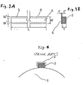
- FEP film 5 having a thickness (t") of 25 ⁇ m and a width (W') of 3 mm was disposed between a NORMEX felt 3 (product of Du Pont de Namors & Inc.) having a thickness (t) of 8 mm, a width (W) of 20 mm and a length (L) of 300 mm and a porous tetrafluoroethylene resin membrane 4 (product of SUMITOMO ELECTRIC INDUSTRIES, LTD. known as POREFLON) having a pore diameter of 0.5 ⁇ m, and a porosity of 70% and a thickness (t') of 300 pm along each longitudinal edge of membrane 4.
- NORMEX felt 3 product of Du Pont de Namors & Inc.
- POREFLON porous tetrafluoroethylene resin membrane 4
- the applicator constructed as hereinabove described was installed for a fixing roller in a plain paper copying machine. It was treated continuously for 50,000 sheets of paper. There was neither any separation of the membrane from the felt nor any clogging of the felt with the toner, but the felt was still usable if an appropriate supply of the releasing agent was continued. The test consumed about 15g of the releasing agent.
Abstract
Description
- This invention relates to a releasing agent applicator for use in, for example, a plain paper copying machine or a facsimile apparatus.
- Referring to Fig. 5, a fixing mechanism in a plain paper copying machine essentially comprises a hot fixing roller 1 and an electric
pressing roller 13, such as a rubber roller.Paper 11 is passed between therollers 1 and 13 and heated under pressure, whereby thetoner 12 which has been transferred onto thepaper 11 is fixed. It also includes ablade 14 and apeeling pawl 15. - When the paper is fed between the rollers, it is likely to stick to, and get wound on, the roller or rollers resulting in the failure of the toner to be properly fixed. It is also likely that the toner may adhere to the fixing roller and thereby cause the formation of a double image (the so-called offset phenomenon). It is, therefore, usual to apply a releasing agent to the fixing and pressing rollers. Silicone oil is usually used as the releasing agent.
- A conventional device for applying a releasing agent to those rollers in a low-speed general-purpose copying machine comprises a heat resistant felt 3 impregnated with silicone oil and attached to a
housing 2 formed from a heat resistant plastic or metal, as shown in Fig. 4. It is simple in construction and inexpensive. This device has, however, a number of drawbacks as will hereunder be pointed out. -
- (1) The toner which has been offset on the fixing roller clogs that surface of the felt which is brought into contact with the roller, and disables the felt to apply oil to the roller. The toner adhering to the felt damages the surface-of the fixing roller. Therefore, it is necessary to change the felt as often as each time about 10,000 sheets of paper have been printed.
- (2) It is impossible to adjust the amount of oil which is applied to the roller.
- It is an object of this invention to provide an improved releasing agent applicator and applying method which solves the drawbacks of the prior art as hereinabove pointed out.
- This object is attained by a device which includes a porous polymer membrane disposed between a heat resistant felt for holding a releasing agent and a fixing roller, and a heat resistant polymer film by which the membrane is thermally fused to the felt, except that portion of the membrane which is brought into contact with the fixing roller. The felt may then be impregnated with a releasing agent and the assembly may be placed contiguous with the fixing roller to cause releasing agent to be applied to the roller.
- This invention has the following advantages:
- (1) The felt has a long life without being clogged if it is appropriately supplied with oil; and
- (2) It is possible to adjust the amount of oil which is applied to the roller.
- These and other objects and advantages of this invention will beccne more apparent and more readily appreciated from the following detailed description of the presently preferred explanary embodiment, taken in conjunction with the accompanying drawings of which:
- Fig. 1A is a front elevational.view of a combination of a felt and a porous tetrafluoroethylene resin membrane bonded thereto according to this invention;
- Fig. 1B is a side elevational view thereof;
- Fig. 2 is a side elevational view of a releasing agent applicator embodying this invention and including the combination of Figs. lA and 1B;
- Fig. 3A is a front elevational view showing a specific example of this invention;
- Fig. 3B is a side elevational view thereof;
- Fig. 4 is a side elevational view of a conventional applicator; and
- Fig. 5 is a schematic view showing the general principle of a copying machine.
- Referring to Fig. 2, a releasing agent applicator embodying this invention comprises a
housing 2 and a heat resistant felt 3 attached thereto and impregnated with a releasing agent, usually silicone oil. A poroustetrafluoroethylene resin membrane 4 is disposed between a fixing roller 1 and felt 3 and a heatresistant polymer film 5, such as a film of FEP (tetrafluoroethylene-hexafluoropropylene copolymer), is thermally fused between felt 3 andmembrane 4, as shown in Figs. 1A and 1B.FEP film 5 is disposed between felt 3 andmembrane 4 except that portion ofmembrane 4 which contacts fixing roller 1, so that oil may be supplied from felt 3 to roller 1 throughmembrane 4. -
Porous tetrafluoroethylene membrane 4 keeps felt 3 from being clogged by the toner and provides it with improved protection against abrasion by roller 1. It is possible to adjust the amount of the releasing agent which is applied throughmembrane 4, if the pore diameter ofmembrane 4 and its porosity are appropriately selected. - The invention will now be described more specifically by way of example.
-
FEP film 5 having a thickness (t") of 25 µm and a width (W') of 3 mm was disposed between a NORMEX felt 3 (product of Du Pont de Namors & Inc.) having a thickness (t) of 8 mm, a width (W) of 20 mm and a length (L) of 300 mm and a porous tetrafluoroethylene resin membrane 4 (product of SUMITOMO ELECTRIC INDUSTRIES, LTD. known as POREFLON) having a pore diameter of 0.5 µm, and a porosity of 70% and a thickness (t') of 300 pm along each longitudinal edge ofmembrane 4. The whole was heated at a temperature of 320°C to 400°C under pressure, wherebymembrane 4 was bonded to felt 3 along each longitudinal edge thereof with a bonding region S (see Fig. lA) having a width of 3 mm.Felt 3 was impregnated with 20 g of dimethyl polysiloxane having a viscosity of 3000 cs and attached tohousing 2 so thatporous membrane 4 might face fixing roller 1. - The applicator constructed as hereinabove described was installed for a fixing roller in a plain paper copying machine. It was treated continuously for 50,000 sheets of paper. There was neither any separation of the membrane from the felt nor any clogging of the felt with the toner, but the felt was still usable if an appropriate supply of the releasing agent was continued. The test consumed about 15g of the releasing agent.
- Although only a single embodiment of this invention has been described above in detail, those skilled in the art will appreciate that many modifications are possible within the spirit and teaching of this invention. Accordingly, all such modifications are intended to be included within the scope of this invention as defined by the following claims.
Claims (7)
Applications Claiming Priority (2)
| Application Number | Priority Date | Filing Date | Title |
|---|---|---|---|
| JP125675/84 | 1984-06-18 | ||
| JP59125675A JPS614090A (en) | 1984-06-18 | 1984-06-18 | Coating device of releasing agent |
Publications (2)
| Publication Number | Publication Date |
|---|---|
| EP0183903A1 true EP0183903A1 (en) | 1986-06-11 |
| EP0183903B1 EP0183903B1 (en) | 1989-09-20 |
Family
ID=14915874
Family Applications (1)
| Application Number | Title | Priority Date | Filing Date |
|---|---|---|---|
| EP85106847A Expired EP0183903B1 (en) | 1984-06-18 | 1985-06-03 | Method and apparatus for applying a releasing agent |
Country Status (4)
| Country | Link |
|---|---|
| US (1) | US4668537A (en) |
| EP (1) | EP0183903B1 (en) |
| JP (1) | JPS614090A (en) |
| DE (1) | DE3573176D1 (en) |
Cited By (3)
| Publication number | Priority date | Publication date | Assignee | Title |
|---|---|---|---|---|
| WO1993008512A1 (en) * | 1991-10-26 | 1993-04-29 | W.L. Gore & Associates (Uk) Limited | Oil transfer component |
| EP0661610A2 (en) * | 1993-12-29 | 1995-07-05 | Fuji Xerox Co., Ltd. | Fixing apparatus for image forming apparatus |
| US5478423A (en) * | 1993-09-28 | 1995-12-26 | W. L. Gore & Associates, Inc. | Method for making a printer release agent supply wick |
Families Citing this family (8)
| Publication number | Priority date | Publication date | Assignee | Title |
|---|---|---|---|---|
| US4942433A (en) * | 1989-05-15 | 1990-07-17 | Eastman Kodak Company | Fixing method and apparatus |
| GB2265857B (en) * | 1992-04-07 | 1995-07-19 | Gore & Ass | Oil reservoir |
| GB9207571D0 (en) * | 1992-04-07 | 1992-05-20 | Gore W L & Ass Uk | Oil reservoir |
| JPH0736298A (en) * | 1993-07-19 | 1995-02-07 | Fuji Xerox Co Ltd | Fixing device |
| US5913384A (en) * | 1996-06-03 | 1999-06-22 | Charles Williams | Treadmill lubricating devices and methods |
| US6750848B1 (en) | 1998-11-09 | 2004-06-15 | Timothy R. Pryor | More useful man machine interfaces and applications |
| US6071354A (en) * | 1999-06-25 | 2000-06-06 | Williams; Charles | Methods of cleaning treadmills |
| US6212355B1 (en) | 1999-08-23 | 2001-04-03 | Tex Tech Industries | Oil metering supply apparatus and method for applying an evenly distributed release oil onto a fuser roller |
Citations (2)
| Publication number | Priority date | Publication date | Assignee | Title |
|---|---|---|---|---|
| US4182263A (en) * | 1977-01-27 | 1980-01-08 | Siemens Aktiengesellschaft | Device for feeding fuser oil to the surface of a fixing roller |
| DE3016098A1 (en) * | 1979-04-28 | 1980-11-13 | Canon Kk | FIXING DEVICE |
Family Cites Families (1)
| Publication number | Priority date | Publication date | Assignee | Title |
|---|---|---|---|---|
| US4309957A (en) * | 1977-01-03 | 1982-01-12 | Xerox Corporation | Wick for dispensing fuser oil |
-
1984
- 1984-06-18 JP JP59125675A patent/JPS614090A/en active Pending
-
1985
- 1985-06-03 EP EP85106847A patent/EP0183903B1/en not_active Expired
- 1985-06-03 DE DE8585106847T patent/DE3573176D1/en not_active Expired
- 1985-06-11 US US06/743,379 patent/US4668537A/en not_active Expired - Fee Related
Patent Citations (2)
| Publication number | Priority date | Publication date | Assignee | Title |
|---|---|---|---|---|
| US4182263A (en) * | 1977-01-27 | 1980-01-08 | Siemens Aktiengesellschaft | Device for feeding fuser oil to the surface of a fixing roller |
| DE3016098A1 (en) * | 1979-04-28 | 1980-11-13 | Canon Kk | FIXING DEVICE |
Non-Patent Citations (2)
| Title |
|---|
| PATENTS ABSTRACTS OF JAPAN, vol. 5, no. 32 (P-50)[704], 27th February 1981; & JP - A - 55 153 974 (CANON K.K.) 01-12-1980 * |
| PATENTS ABSTRACTS OF JAPAN, vol. 7, no. 23 (P-171)[1168], 29th January 1983; & JP - A - 57 177 174 (CANON K.K.) 30-10-1982 * |
Cited By (8)
| Publication number | Priority date | Publication date | Assignee | Title |
|---|---|---|---|---|
| WO1993008512A1 (en) * | 1991-10-26 | 1993-04-29 | W.L. Gore & Associates (Uk) Limited | Oil transfer component |
| US5478423A (en) * | 1993-09-28 | 1995-12-26 | W. L. Gore & Associates, Inc. | Method for making a printer release agent supply wick |
| US5690739A (en) * | 1993-09-28 | 1997-11-25 | W. L. Gore & Associates, Inc. | Release agent supply wick for printer apparatus and method for making and using same |
| US5709748A (en) * | 1993-09-28 | 1998-01-20 | W. L. Gore & Associates, Inc. | Release agent supply wick for printer apparatus |
| EP0661610A2 (en) * | 1993-12-29 | 1995-07-05 | Fuji Xerox Co., Ltd. | Fixing apparatus for image forming apparatus |
| EP0661610A3 (en) * | 1993-12-29 | 1996-03-06 | Fuji Xerox Co Ltd | Fixing apparatus for image forming apparatus. |
| US5619315A (en) * | 1993-12-29 | 1997-04-08 | Fuji Xerox Co., Ltd. | Fixing apparatus using a coated elastic member for use in an image forming apparatus |
| AU681467B2 (en) * | 1993-12-29 | 1997-08-28 | Fuji Xerox Co., Ltd. | Fixing apparatus for image forming apparatus |
Also Published As
| Publication number | Publication date |
|---|---|
| EP0183903B1 (en) | 1989-09-20 |
| DE3573176D1 (en) | 1989-10-26 |
| US4668537A (en) | 1987-05-26 |
| JPS614090A (en) | 1986-01-09 |
Similar Documents
| Publication | Publication Date | Title |
|---|---|---|
| CA1067132A (en) | Fuser roll having a non-uniform cross section | |
| EP0183903A1 (en) | Method and apparatus for applying a releasing agent | |
| US6117528A (en) | Oil delivery sheet material for use in various printer devices | |
| JPH08160801A (en) | Fixing device | |
| JPS622283A (en) | Elastic rotating body and fixing device | |
| EP0291081B1 (en) | Elastic roller for fixing and method of producing the same | |
| US4336992A (en) | Apparatus for removing copy sheets from a roll fuser | |
| US5697036A (en) | Single roll RAM system | |
| US4770116A (en) | Contact fuser apparatus with release agent management system | |
| GB1570876A (en) | Temperature sensing | |
| EP0174474A1 (en) | Release agent applicator | |
| JPH07191567A (en) | Thermopressure roller and fixing device | |
| JPS5952269A (en) | Fixation device | |
| JPH02186376A (en) | Image forming device | |
| JPS63229477A (en) | Device for coating and cleaning release agent | |
| JPS61184575A (en) | Fixing device | |
| EP0855631A3 (en) | Fixing device and manufacturing method of blade used for the same | |
| JPS61240266A (en) | Fixing device for copying machine or the like | |
| JPH0119148Y2 (en) | ||
| JPS61103179A (en) | Release agent coater | |
| JPH0520754B2 (en) | ||
| JPS6318029Y2 (en) | ||
| JPH02160274A (en) | Fixing device | |
| JPH08120096A (en) | Sliding material | |
| JPH0477777A (en) | Fixing device in electrophotographic printing device |
Legal Events
| Date | Code | Title | Description |
|---|---|---|---|
| PUAI | Public reference made under article 153(3) epc to a published international application that has entered the european phase |
Free format text: ORIGINAL CODE: 0009012 |
|
| AK | Designated contracting states |
Kind code of ref document: A1 Designated state(s): DE GB IT |
|
| 17P | Request for examination filed |
Effective date: 19860716 |
|
| 17Q | First examination report despatched |
Effective date: 19880120 |
|
| GRAA | (expected) grant |
Free format text: ORIGINAL CODE: 0009210 |
|
| AK | Designated contracting states |
Kind code of ref document: B1 Designated state(s): DE GB IT |
|
| REF | Corresponds to: |
Ref document number: 3573176 Country of ref document: DE Date of ref document: 19891026 |
|
| ITF | It: translation for a ep patent filed |
Owner name: MODIANO & ASSOCIATI S.R.L. |
|
| PLBE | No opposition filed within time limit |
Free format text: ORIGINAL CODE: 0009261 |
|
| STAA | Information on the status of an ep patent application or granted ep patent |
Free format text: STATUS: NO OPPOSITION FILED WITHIN TIME LIMIT |
|
| 26N | No opposition filed | ||
| ITTA | It: last paid annual fee | ||
| PGFP | Annual fee paid to national office [announced via postgrant information from national office to epo] |
Ref country code: GB Payment date: 19960528 Year of fee payment: 12 |
|
| PGFP | Annual fee paid to national office [announced via postgrant information from national office to epo] |
Ref country code: DE Payment date: 19960612 Year of fee payment: 12 |
|
| PG25 | Lapsed in a contracting state [announced via postgrant information from national office to epo] |
Ref country code: GB Effective date: 19970603 |
|
| GBPC | Gb: european patent ceased through non-payment of renewal fee |
Effective date: 19970603 |
|
| PG25 | Lapsed in a contracting state [announced via postgrant information from national office to epo] |
Ref country code: DE Free format text: LAPSE BECAUSE OF NON-PAYMENT OF DUE FEES Effective date: 19980303 |