EP0183864B1 - Connection of at least two roof trusses with several, essentially horizontally disposed purlins suspended from the trusses and secured against protusion - Google Patents
Connection of at least two roof trusses with several, essentially horizontally disposed purlins suspended from the trusses and secured against protusion Download PDFInfo
- Publication number
- EP0183864B1 EP0183864B1 EP84114734A EP84114734A EP0183864B1 EP 0183864 B1 EP0183864 B1 EP 0183864B1 EP 84114734 A EP84114734 A EP 84114734A EP 84114734 A EP84114734 A EP 84114734A EP 0183864 B1 EP0183864 B1 EP 0183864B1
- Authority
- EP
- European Patent Office
- Prior art keywords
- purlin
- bracket
- locking
- bent
- fork
- Prior art date
- Legal status (The legal status is an assumption and is not a legal conclusion. Google has not performed a legal analysis and makes no representation as to the accuracy of the status listed.)
- Expired
Links
Images


Classifications
-
- E—FIXED CONSTRUCTIONS
- E04—BUILDING
- E04H—BUILDINGS OR LIKE STRUCTURES FOR PARTICULAR PURPOSES; SWIMMING OR SPLASH BATHS OR POOLS; MASTS; FENCING; TENTS OR CANOPIES, IN GENERAL
- E04H15/00—Tents or canopies, in general
- E04H15/32—Parts, components, construction details, accessories, interior equipment, specially adapted for tents, e.g. guy-line equipment, skirts, thresholds
- E04H15/34—Supporting means, e.g. frames
-
- E—FIXED CONSTRUCTIONS
- E04—BUILDING
- E04B—GENERAL BUILDING CONSTRUCTIONS; WALLS, e.g. PARTITIONS; ROOFS; FLOORS; CEILINGS; INSULATION OR OTHER PROTECTION OF BUILDINGS
- E04B1/00—Constructions in general; Structures which are not restricted either to walls, e.g. partitions, or floors or ceilings or roofs
- E04B1/343—Structures characterised by movable, separable, or collapsible parts, e.g. for transport
- E04B1/34315—Structures characterised by movable, separable, or collapsible parts, e.g. for transport characterised by separable parts
- E04B1/34326—Structures characterised by movable, separable, or collapsible parts, e.g. for transport characterised by separable parts mainly constituted by longitudinal elements
Definitions
- the invention relates to a connection of at least two roof trusses with a plurality of substantially horizontal purlins, which are each formed at their two ends with downward-facing support hooks which engage with the hanging straps fastened with the roof trusses and are secured against unintentional lifting out of the vehicle by means of a securing device
- Hanging brackets are secured, the purlin having in its end regions a bracket joint extending transversely to the purlin longitudinal extension and parallel to the purlin floor at a predetermined distance, which is provided with pivotable locking brackets, in particular for the construction of tent scaffolding.
- a securing of the connecting purlins against undesired lifting out of the hanging tabs connected to the binder is generally achieved in that at the lower end of the leg of the carrying hook facing the binder, below the tab, there is a hole for receiving an engaging in the binder Locking pin is provided.
- a disadvantage of this secure locking is the need to insert or remove the pin at the respective height.
- connection between the purlins is secured in a supporting structure for a tent in that a securing bracket is provided on at least one end of each purlin, which is pivotally connected to the purlin about an axis running transversely to the longitudinal axis of the purlin and reaches under the hanging tab.
- a disadvantage of this design is that the locking mechanism does not engage in the hanging tab, but extends over it from the outside. This means that at a, e.g. B. always possible assembly failure, conditional, resulting inclined position of the vertical axis of the girder profile, the risk of lifting the attack bar is given.
- Fixing the hook position to the truss can in no way be ensured by such a hold-up bar.
- connection according to the type described at the outset, which prevents an independent removal of the anti-excavation device even when the binder is tilted about its vertical axis, and which, when the anti-excavation device is engaged, also reduces the usual play between the Hook and the binder side walls allows.
- the locking bracket with its end facing away from the binder is designed to be heavier than the bracket end pointing to the hanging tab and is curved such that in the locked position the bracket end runs approximately parallel to the hook at a zero-leading distance and the subsequent angling of the locking bracket rests against the inner edge of the suspension bracket, and that the angle between the bracket end and the subsequent bend is formed by or over 90 °, and the further bend leading to the bracket joint is designed to rise, while the overweight end, relative to the purlin plane, follows is angled below, and the end region is designed as a fork stop for a purlin lifting fork.
- the positive engagement of the locking bracket in the hook-in tab connected to the purlin provides both a safe, simple locking and a reduction in the play of the purlin in its longitudinal extent between the binders.
- the fork itself is formed by a U-profile that is connected to the bottom of the purlin, it is expedient that the U-profile forming the fork is screwed to the part of the hook that reaches into the purlin, including the bottom of the purlin.
- the overweight end of the locking bracket is connected to a downward weight piece, the weight piece assuming the function of the fork stop for the lifting fork .
- the overweight end of the locking bracket is provided with a weight arranged on the top, and that the overweight end, relative to the purlin plane, is angled downward and the end region is designed as a fork stop for a lifting fork.
- the fork stop for the lifting fork which is formed by a bend, can be made relatively short.
- the locking position should be summarized again, the criterion of which is that when the purlin locked in the suspension bracket is lifted, the end of the bracket rests against the hook at an acute angle, and the angling of the locking bracket below the area or area delimited by the thickness of the suspension bracket Line lies essentially plane-parallel or parallel.
- the purlin is only equipped on one side with a locking bracket which is rotatably arranged on a bracket joint.
- connection according to the invention secured against unintentional lifting, of at least two roof trusses with a plurality of substantially horizontal purlins, each of which is formed with downward-facing support hooks which engage in hanging tabs, is explained in more detail in an exemplary embodiment.
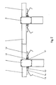
- Figure Z shows the system of arranging, connecting and locking binders and purlins as a compilation.
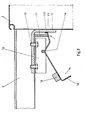
- Figure 1 shows a connection joint between purlin and truss, the purlin in the longitudinal direction of its extension including the safety device in its longitudinal extension, as well as the hanging tab are cut in the middle: the longer, d.
- Obese part of the locking bracket has an additional weight-increasing fork stop for engaging a lifting fork used in assembly.
- Figure 2 shows an analog design to Figure 1, but with an additional weight arranged in the end region, which is also effective as a fork stop.
- Figure 3 also corresponds to Figures 1 and 2; the additional weight is arranged upward on the locking bracket, and an end angled by 90 °, which is also effective as a fork stop, directed downward.
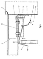
- FIG. 4 shows FIG. 1 with the lifting fork attached in the lifting or lifting position of the purlin.
- the bearing fork formed by a U-shaped profile 1.2 for receiving the bow joint 1.4 is connected from below to the purlin floor by screws 1.9, which in turn engage in corresponding threads of the inside hook 1.1.
- the position of the bow joint 1.4 is determined so that the shorter, d. H. the less important part of the bracket 1.3 is directed approximately parallel to the hook 1.1 with its bracket end 1.3.1, and with its angled 1.3.2 adjoining the inner edge of the flap 2.1, and the further angled 1.3.3 leads to the bow joint 1.4.
- the subsequent overweight end 1.3.4 leads into a fork stop 1.5 which reinforces the overweight and is angled by 90 °, this additionally reinforcing the excess weight.
- the bracket end 1.3.1 lies at an acute angle on the hook surface, while the bend 1.3.2 of the locking bracket 1.3 downwards delimits the area delimited by the thickness of the suspension brackets 2.1 or line lies essentially plane-parallel or parallel. It is thus clearly locked against unwanted excavation.
- FIG. 4 If the overweight end of the locking bracket 1.3 is raised by a lifting fork 3, FIG. 4, then, as an embodiment according to FIG. 1 shows in the unlocked position, the purlin can be easily lifted by the lifting fork 3.
- Figure 2 shows the equipment of the bow end 1.3.4 with a separate, downward weight 1.7, which can also take over the function of the fork stop.
- the bow end 1.3.4 is designed with an upward weight 1.8, whereby section 1.3.4. same as in FIG. 1, transferred to a stop 1.6, which, however, can be kept shorter than stop 1.5 in FIG. 1 as a result of the additional weight.
- the trusses and purlins are usually extruded aluminum profiles, while the hanging tabs and hooks, as well as the locking mechanism, are preferably made of steel.
Abstract
Description
Die Erfindung betrifft eine Verbindung von mindestens zwei Dachbindern mit mehreren, im wesentlichen horizontal verlaufenden Pfetten, die an ihren beiden Enden jeweils mit nach unten gerichteten Traghaken ausgebildet sind, die an die mit den Dachbindern befestigten Einhängelaschen eingreifen und durch eine Sicherungsvorrichtung gegen unbeabsichtigtes Ausheben aus den Einhängelaschen gesichert sind, wobei die Pfette in ihren Endbereichen ein quer zur Pfettenlängserstreckung und parallel zum Pfettenboden in einem vorbestimmten Abstand sich erstreckendes Bügelgelenk aufweist, das mit verschwenkbaren Verriegelungsbügeln versehen ist, insbesondere für die Erstellung von Zeltgerüsten.The invention relates to a connection of at least two roof trusses with a plurality of substantially horizontal purlins, which are each formed at their two ends with downward-facing support hooks which engage with the hanging straps fastened with the roof trusses and are secured against unintentional lifting out of the vehicle by means of a securing device Hanging brackets are secured, the purlin having in its end regions a bracket joint extending transversely to the purlin longitudinal extension and parallel to the purlin floor at a predetermined distance, which is provided with pivotable locking brackets, in particular for the construction of tent scaffolding.
Bei bekannten Konstruktionen wird eine Sicherung der verbindenden Pfetten gegen unerwünschtes Ausheben aus den mit dem Binder verbundenen Einhängelaschen in aller Regel dadurch erreicht, daß am unteren Ende des dem Binder zugerichteten Schenkels des Traghakens, unterhalb der Lasche, eine Bohrung zur Aufnahme eines in den Binder greifenden Sicherungsstiftes vorgesehen ist.In known constructions, a securing of the connecting purlins against undesired lifting out of the hanging tabs connected to the binder is generally achieved in that at the lower end of the leg of the carrying hook facing the binder, below the tab, there is a hole for receiving an engaging in the binder Locking pin is provided.
Nachteilig bei dieser anundfürsich sicheren Verriegelung ist jedoch das in der jeweiligen Höhenlage erforderliche Einbringen bzw. Herausnehmen des Stiftes.A disadvantage of this secure locking, however, is the need to insert or remove the pin at the respective height.
Durch das DE-GM 83 10 306 wird bei einem Traggerüst für ein Zelt die Verbindung zwischen den Pfetten dadurch aushebegesichert, daß an mindestens einem Ende jeder Pfette ein Sicherungsbügel vorgesehen ist, der um eine quer zur Pfettenlängsachse verlaufende Achse schwenkbar an der Pfette angeschlossen ist und die Einhängelasche untergreift.By DE-GM 83 10 306, the connection between the purlins is secured in a supporting structure for a tent in that a securing bracket is provided on at least one end of each purlin, which is pivotally connected to the purlin about an axis running transversely to the longitudinal axis of the purlin and reaches under the hanging tab.
Nachteilig bei dieser Konzeption ist, daß der Verriegelungsmechanismus nicht in die Einhängelasche eingreift, sondern diese von außen übergreift. Dies bedeutet, daß bei einer, z. B. immer möglichen Montagepanne, bedingten, sich einstellenden Schräglage der Hochachse des Binderprofiles, die Gefahr eines Abhebens des Überfallbügels gegeben ist.A disadvantage of this design is that the locking mechanism does not engage in the hanging tab, but extends over it from the outside. This means that at a, e.g. B. always possible assembly failure, conditional, resulting inclined position of the vertical axis of the girder profile, the risk of lifting the attack bar is given.
Des weiteren muß bemerkt werden, daß die im Interesse einer bequemen Einhängung der Pfette in die in ihrem Lichtmaß zum Binder groß zu haltenden Einhängelaschen die Eigenstabilität des noch nicht fertig montierten Traggerüstes stark mindert. Da die jeweils zu addierenden Freiräume zwischen den Haken und den Einhängelaschen eine Verschiebung der Pfette in Richtung ihrer Längserstreckung bei noch nicht endgültig fixierten Stielen bis zu etwa 20 mm zuläßt, so daß die lotrechte Ausrichtung der Stiele, zumindest erschwert, wenn nicht gar in möglichen Einzelfällen verhindert wird.Furthermore, it must be noted that, in the interest of a convenient hanging of the purlin in the mounting brackets which are to be kept large in terms of their light dimensions relative to the binder, the inherent stability of the support frame which has not yet been fully assembled is greatly reduced. Since the free space to be added between the hooks and the hook-in tabs allows the purlin to be shifted in the direction of its longitudinal extent with stems that have not yet been finally fixed, so that the vertical alignment of the stems is at least difficult, if not impossible in individual cases is prevented.
Eine Fixierung der Hakenlage zum Binder gerichtet, kann durch einen solchen Überfallbügel keinenfalls gesichert werden.Fixing the hook position to the truss can in no way be ensured by such a hold-up bar.
Die zeichnerich nicht dargestellte Heranführung des Bügels an den Haken widerspricht anundfüsich der Grundkonzeption eines Überfallbügels.The approach of the stirrup to the hook, not shown in the drawing, contradicts the basic concept of a hold-up stirrup.
Dies berücksichtigend, ist es Aufgabe dieser Erfindung, eine Verbindung nach der eingangs beschriebenen Art zu nennen, die auch bei Verkantung des Binders um seine Hochachse eine selbständige Aufhebung der Aushubsicherung verhindert, und die gleichfalls, bei eingerasteter Aushubsicherung, eine Reduzierung des üblichen Spiels zwischen den Haken und den Binderseitenwänden ermöglicht.Taking this into account, it is the object of this invention to name a connection according to the type described at the outset, which prevents an independent removal of the anti-excavation device even when the binder is tilted about its vertical axis, and which, when the anti-excavation device is engaged, also reduces the usual play between the Hook and the binder side walls allows.
Die erfindungsgemäße Lösung dieser Aufgabe sieht vor, daß der Verriegelungsbügel mit seinem vom Binder abweisenden Ende schwerer als das zur Einhängelasche weisende Bügelende ausgebildet und so gebogen ist, daß in verriegelter Stellung das Bügelende in gegen Null führendem Abstand etwa parallel zum Haken verläuft und die anschließende Abwinklung des Verriegelungsbügels der inneren Kante der Einhängelasche anliegt, und daß hierbei der Winkel zwischen Bügelende und die anschließende Abwinklung um oder über 90°, und die weitere, zum Bügelgelenk führende Abwinklung ansteigend ausgebildet ist, während das übergewichtige Ende, bezogen zur Ebene der Pfette, nach unten abgewinkelt ist, und der Endbereich als Gabelanschlag für eine Pfettenhubgabel ausgebildet ist.The solution to this problem according to the invention provides that the locking bracket with its end facing away from the binder is designed to be heavier than the bracket end pointing to the hanging tab and is curved such that in the locked position the bracket end runs approximately parallel to the hook at a zero-leading distance and the subsequent angling of the locking bracket rests against the inner edge of the suspension bracket, and that the angle between the bracket end and the subsequent bend is formed by or over 90 °, and the further bend leading to the bracket joint is designed to rise, while the overweight end, relative to the purlin plane, follows is angled below, and the end region is designed as a fork stop for a purlin lifting fork.
Durch das außerhalb des Pfettenquerschnittes und unterhalb des Pfettenbodens im Abstand angeordnete Bügelgelenk für den verschwenkbaren Verriegelungshebel wird dessen formschlüssiger Eingriff in die jeweils den Traghaken der Pfette aufnehmende, dem Binder verbundene Einhängelasche erreicht, wobei der Formschlußeingriff selbstverständlich gegenüber jeder lediglich kraftschlüssig wirksamen Überfallbügelsicherung nicht näher zu erläuternde Vorteile aufweist.The outside of the purlin cross-section and below the purlin base at a distance from the hinge joint for the pivotable locking lever ensures that it engages positively in the hook of the purlin receiving the connecting strap connected to the binder, the form-locking engagement of course not being explained in detail with respect to any merely non-positively effective hold-up lever protection Has advantages.
Das zur Einhängelasche weisende Bügelende nimmt dabei, nach Entfernung der Hubgabel, bedingt durch das höhere Gewicht des vom Drehgelenk vom Binder abgerichteten, schwereren Endes des Verriegelungsbügels selbständig eine, etwa parallel zum Haken verlaufende Lage ein, wobei die Fortsetzung des Bügels der inneren Kante der Einhängelasche von unten anliegt.When the lifting fork is removed, the end of the bracket pointing towards the hanging bracket automatically takes on a position approximately parallel to the hook due to the higher weight of the heavier end of the locking bracket which is pivoted from the hinge by the binder, with the bracket continuing the inner edge of the hanging bracket from below.
Der dem Drehgelenk anschließende übergewichtige Teil des Bügels endet, wie erwähnt, in einem Gabelanschlag für die Pfettenhubgabel.The overweight part of the bracket adjoining the swivel ends, as mentioned, in a fork stop for the purlin lifting fork.
Durch den Formschlußeingriff des Verriegelungsbügels in die mit der Pfette verbundene Einhängelasche ist sowohl eine sichere, einfache Verriegelung als auch eine Reduzierung des Spiels der Pfette in ihrer Längserstreckung zwischen den Bindern gegeben.The positive engagement of the locking bracket in the hook-in tab connected to the purlin provides both a safe, simple locking and a reduction in the play of the purlin in its longitudinal extent between the binders.
Zur Lagerung des Bügelgelenkes in der bereits erwähnten Position wird vorgeschlagen, daß dieses innerhalb einer am Boden der Pfette ausgebildeten Gabel erfolgt, wobei die Gabelweite mit der Breite des Verriegelungsbügels korrespondiert. Die Gabel selbst wird durch ein U-Profil gebildet, das mit dem Boden der Pfette verbunden ist, wobei es zweckmäßig ist, daß das die Gabel bildende U-Profil mit dem in die Pfette greifenden Teil des Hakens, hierbei den Boden der Pfette einschließend, verschraubt ist.To mount the bracket joint in the position already mentioned, it is proposed that this take place within a fork formed on the bottom of the purlin, the fork width corresponding to the width of the locking bracket. The fork itself is formed by a U-profile that is connected to the bottom of the purlin, it is expedient that the U-profile forming the fork is screwed to the part of the hook that reaches into the purlin, including the bottom of the purlin.
Anstelle der eingangs vorgeschlagenen Ausbildung des Gabelanschlages für die Hubgabel durch eine weitere, nach unten gerichtete Abwinklung des Verriegelungsbügels kann vorgesehen werden, daß dem übergewichtigen Ende des Verriegelungsbügels ein nach unten gerichtetes Gewichtsstück verbunden ist, wobei das Gewichtsstück die Funktion des Gabelanschlages für die Hubgabel mit übernimmt.Instead of the initially proposed design of the fork stop for the lifting fork by a further, downward angling of the locking bracket, it can be provided that the overweight end of the locking bracket is connected to a downward weight piece, the weight piece assuming the function of the fork stop for the lifting fork .
Es ist ebenfalls möglich, daß das übergewichtige Ende des Verriegelungsbügels mit einem oberseitig angeordneten Gewichtsstück versehen ist, und daß das übergewichtige Ende, bezogen auf die Ebene der Pfette, nach unten abgewinkelt, und der Endbereich als Gabelanschlag für eine Hubgabel ausgebildet ist.It is also possible that the overweight end of the locking bracket is provided with a weight arranged on the top, and that the overweight end, relative to the purlin plane, is angled downward and the end region is designed as a fork stop for a lifting fork.
Selbstverständlich kann durch die oberseitige Anordnung des Gewichtsstückes der durch eine Abwinklung gebildete Gabelanschlag für die Hubgabel relativ kurz ausgebildet sein.Of course, due to the upper-side arrangement of the weight piece, the fork stop for the lifting fork, which is formed by a bend, can be made relatively short.
Abschließend soll nochmals zusammengefaßt die Verriegelungsposition definiert werden, deren Kriterium es ist, daß bei Hub der in der Einhängelasche verriegelten Pfette das Bügelende gegen den Haken in spitzem Winkel anliegt, und die Abwinklung des Verriegelungsbügels nach unten der durch die Dickenerstreckung der Einhängelasche abgrenzend gebildeten Fläche oder Linie im wesentlichen planparallel oder parallel aufliegt.Finally, the locking position should be summarized again, the criterion of which is that when the purlin locked in the suspension bracket is lifted, the end of the bracket rests against the hook at an acute angle, and the angling of the locking bracket below the area or area delimited by the thickness of the suspension bracket Line lies essentially plane-parallel or parallel.
Zur Verringerung des Spieles der Pfetten zwischen jeweils zwei Bindern wird ebenfalls nochmals zusammenfassend festgehalten, daß bei beidseitig zwischen zwei Bindern verriegelter Pfette in deren Längserstreckung das Maß des Spiels der Haken in den Einhängelaschen durch den beidseitigen Eingriff der Bügelenden der Verriegelungsbügel reduziert ist.To reduce the play of the purlins between two trusses, it is also summarized again that in the case of purlins that are locked on both sides between two trusses, the length of the play of the hooks in the suspension brackets is reduced by the two-sided engagement of the temple ends of the locking bracket.
Bei besonderen Montagebedingungen kann vorgesehen werden, daß die Pfette lediglich einseitig mit einem an einem Bügelgelenk drehbar angeordneten Verriegelungsbügel ausgerüstet ist.Under special assembly conditions it can be provided that the purlin is only equipped on one side with a locking bracket which is rotatably arranged on a bracket joint.
Damit sind die Forderungen der Aufgabenstellung auf einfache Weise sicher gelöst.In this way, the requirements of the task are easily solved.
Die erfindungsgemäße, gegen unbeabsichtigtes Ausheben gesicherte Verbindung von mindestens zwei Dachbindern mit mehreren, im wesentlichen horizontal verlaufenden Pfetten, die jeweils mit nach unten gerichteten, in Einhängelaschen eingreifende Traghaken ausgebildet sind, wird in einer beispielsweisen Ausführung näher erläutert.The connection according to the invention, secured against unintentional lifting, of at least two roof trusses with a plurality of substantially horizontal purlins, each of which is formed with downward-facing support hooks which engage in hanging tabs, is explained in more detail in an exemplary embodiment.
Figur Z zeigt als Zusammenstellung das System der Anordnung, Verbindung und Verriegelung von Bindern und Pfetten.Figure Z shows the system of arranging, connecting and locking binders and purlins as a compilation.
Figur 1 zeigt einen Verbindungsstoß zwischen Pfette und Binder, wobei die Pfette in Längsrichtung ihrer Erstreckung einschließlich der Sicherungsvorrichtung in ihrer Längserstreckung, sowie die Einhängelasche mittig geschnitten sind : der längere, d. h. übergewichtige Teil des Verriegelungsbügels weist einen zusätzlich gewichtsverstärkenden Gabelanschlag für den Eingriff einer bei der Montage verwendeten Hubgabel auf.Figure 1 shows a connection joint between purlin and truss, the purlin in the longitudinal direction of its extension including the safety device in its longitudinal extension, as well as the hanging tab are cut in the middle: the longer, d. H. Obese part of the locking bracket has an additional weight-increasing fork stop for engaging a lifting fork used in assembly.
Figur 2 zeigt eine analoge Ausbildung zu Figur 1, jedoch mit einem im Endbereich angeordneten Zusatzgewicht, das gleichfalls als Gabelanschlag wirksam ist.Figure 2 shows an analog design to Figure 1, but with an additional weight arranged in the end region, which is also effective as a fork stop.
Figur 3 korrespondiert ebenfalls mit Figur 1 und 2 ; das Zusatzgewicht ist dabei nach oben gerichtet auf dem Verriegelungsbügel angeordnet, und ein um 90° abgewinkeltes Ende, das ebenfalls als Gabelanschlag wirksam ist, nach unten gerichtet.Figure 3 also corresponds to Figures 1 and 2; the additional weight is arranged upward on the locking bracket, and an end angled by 90 °, which is also effective as a fork stop, directed downward.
Figur 4 zeigt Figur 1 mit angesetzter Hubgabel in Ein- bzw. Aushubposition der Pfette.FIG. 4 shows FIG. 1 with the lifting fork attached in the lifting or lifting position of the purlin.
Aus den Figuren 1 bis 3 ist die zu dem Binder 2 verriegelte Position der Pfette 1 ausgewiesen.The position of the purlin 1 locked to the
Die durch ein U-förmiges Profil 1.2 ausgebildete Lagergabel zur Aufnahme des Bügelgelenkens 1.4 ist von unten dem Pfettenboden durch Schrauben 1.9 verbunden, die ihrerseits wieder in korrespondierende Gewinde des innenliegenden Hakens 1.1 eingreifen. Die Gabelweite, d. h. der Abstand zwischen den U-Schenkeln entspricht. mit etwas Spiel, der Breite des verschwenkbaren Verriegelungsbügels 1.3.The bearing fork formed by a U-shaped profile 1.2 for receiving the bow joint 1.4 is connected from below to the purlin floor by screws 1.9, which in turn engage in corresponding threads of the inside hook 1.1. The fork width, d. H. the distance between the U-legs corresponds. with some play, the width of the pivotable locking bracket 1.3.
Die Lage des Bügelgelenkes 1.4 ist dabei so bestimmt, daß der kürzere, d. h. der mindergewichtige, Teil des Bügels 1.3 mit seinem Bügelende 1.3.1 etwa parallel gegen den Haken 1.1 gerichtet ist, und mit seiner etwas über 90° nach unten anschließenden Abwinklung 1.3.2 der inneren Kante der Lasche 2.1 anliegt und die weitere Abwinklung 1.3.3 zum Bügelgelenk 1.4 führt. Das anschließende übergewichtige Ende 1.3.4 führt in einen das Übergewicht verstärkenden, um 90° abgewinkelten Gabelanschlag 1.5 über, wobei dieser das Übergewicht zusätzlich verstärkt.The position of the bow joint 1.4 is determined so that the shorter, d. H. the less important part of the bracket 1.3 is directed approximately parallel to the hook 1.1 with its bracket end 1.3.1, and with its angled 1.3.2 adjoining the inner edge of the flap 2.1, and the further angled 1.3.3 leads to the bow joint 1.4. The subsequent overweight end 1.3.4 leads into a fork stop 1.5 which reinforces the overweight and is angled by 90 °, this additionally reinforcing the excess weight.
Durch den beidseitigen Eingriff der Bügelenden 1.3.1 der Verriegelungsbügel 1.3 in die Einhängelaschen 2.1 wird das Maß des freien Spiels der Haken in den Einhängelaschen reduziert und damit die Bewegungsmöglichkeit des Verbundes Pfette-Binder, erheblich eingeschränkt.The double-sided engagement of the shackle ends 1.3.1 of the locking shackle 1.3 in the hook-in tabs 2.1 reduces the amount of free play of the hooks in the hook-in tabs and thus considerably limits the freedom of movement of the purlin-binder assembly.
Bei Anhub der Pfette 1, sei es durch Druck oder durch Zug, legt sich das Bügelende 1.3.1 in einem spitzen Winkel der Hakenfläche an, während die Abwinklung 1.3.2 des Verriegelungsbügels 1.3 nach unten der durch die Dickenerstreckung der Einhängelaschen 2.1 abgrenzend gebildeten Fläche oder Linie im wesentlichen planparallel oder parallel aufliegt. Sie ist damit gegen unerwünschten Aushub eindeutig verriegelt.When the purlin 1 is lifted, be it by pressure or by pulling, the bracket end 1.3.1 lies at an acute angle on the hook surface, while the bend 1.3.2 of the locking bracket 1.3 downwards delimits the area delimited by the thickness of the suspension brackets 2.1 or line lies essentially plane-parallel or parallel. It is thus clearly locked against unwanted excavation.
Wird das übergewichtige Ende des Verriegelungsbügels 1.3 durch eine Hubgabel 3 angehoben, Fig. 4, so kann, wie eine Ausführung nach Figur 1 in Entriegelungsstellung ausweist, die Pfette mühelos durch die Hubgabel 3 ausgehoben werden.If the overweight end of the locking bracket 1.3 is raised by a lifting fork 3, FIG. 4, then, as an embodiment according to FIG. 1 shows in the unlocked position, the purlin can be easily lifted by the lifting fork 3.
Figur 2 zeigt die Ausrüstung des Bügelendes 1.3.4 mit einem separaten, nach unten gerichteten Gewicht 1.7, das gleichzeitig die Funktion des Gabelanschlages übernehmen kann.Figure 2 shows the equipment of the bow end 1.3.4 with a separate, downward weight 1.7, which can also take over the function of the fork stop.
Nach Figur 3 ist das Bügelende 1.3.4 mit einem nach oben weisenden Gewicht 1.8 ausgebildet, wobei der Abschnitt 1.3.4. gleich wie bei Figur 1, in einen Anschlag 1.6 überführt, der jedoch als Folge des Zusatzgewichtes kürzer gehalten werden kann wie Anschlag 1.5 in Figur 1.According to FIG. 3, the bow end 1.3.4 is designed with an upward weight 1.8, whereby section 1.3.4. same as in FIG. 1, transferred to a stop 1.6, which, however, can be kept shorter than stop 1.5 in FIG. 1 as a result of the additional weight.
Die Binder und Pfetten sind in der Regel strangpreßgezogene Aluminiumprofile, während die Einhängelaschen und die Haken, sowie der Verriegelungsmechanismus vorzugsweise aus Stahl hergestellt sind.The trusses and purlins are usually extruded aluminum profiles, while the hanging tabs and hooks, as well as the locking mechanism, are preferably made of steel.
Claims (8)
Priority Applications (3)
| Application Number | Priority Date | Filing Date | Title |
|---|---|---|---|
| EP84114734A EP0183864B1 (en) | 1984-12-04 | 1984-12-04 | Connection of at least two roof trusses with several, essentially horizontally disposed purlins suspended from the trusses and secured against protusion |
| AT84114734T ATE33511T1 (en) | 1984-12-04 | 1984-12-04 | CONNECTION OF AT LEAST TWO ROOF TISSUES WITH SEVERAL, ESSENTIALLY HORIZONTAL RUNNING, ATTACHED TO THE ROOF TISSUES, EXTRACTION PROTECTIVE PURINS. |
| DE8484114734T DE3470427D1 (en) | 1984-12-04 | 1984-12-04 | Connection of at least two roof trusses with several, essentially horizontally disposed purlins suspended from the trusses and secured against protusion |
Applications Claiming Priority (1)
| Application Number | Priority Date | Filing Date | Title |
|---|---|---|---|
| EP84114734A EP0183864B1 (en) | 1984-12-04 | 1984-12-04 | Connection of at least two roof trusses with several, essentially horizontally disposed purlins suspended from the trusses and secured against protusion |
Publications (2)
| Publication Number | Publication Date |
|---|---|
| EP0183864A1 EP0183864A1 (en) | 1986-06-11 |
| EP0183864B1 true EP0183864B1 (en) | 1988-04-13 |
Family
ID=8192329
Family Applications (1)
| Application Number | Title | Priority Date | Filing Date |
|---|---|---|---|
| EP84114734A Expired EP0183864B1 (en) | 1984-12-04 | 1984-12-04 | Connection of at least two roof trusses with several, essentially horizontally disposed purlins suspended from the trusses and secured against protusion |
Country Status (3)
| Country | Link |
|---|---|
| EP (1) | EP0183864B1 (en) |
| AT (1) | ATE33511T1 (en) |
| DE (1) | DE3470427D1 (en) |
Family Cites Families (3)
| Publication number | Priority date | Publication date | Assignee | Title |
|---|---|---|---|---|
| US2588905A (en) * | 1950-03-07 | 1952-03-11 | Universal Mfg Co | Scaffold bracing |
| DE1973051U (en) * | 1967-06-07 | 1967-11-23 | Licentia Gmbh | FASTENING DEVICE FOR THE POLES OF A TENT FRAMEWORK. |
| ATE6801T1 (en) * | 1980-01-15 | 1984-04-15 | Sgb Group Public Limited Company | SCAFFOLDING SYSTEM. |
-
1984
- 1984-12-04 DE DE8484114734T patent/DE3470427D1/en not_active Expired
- 1984-12-04 AT AT84114734T patent/ATE33511T1/en not_active IP Right Cessation
- 1984-12-04 EP EP84114734A patent/EP0183864B1/en not_active Expired
Also Published As
| Publication number | Publication date |
|---|---|
| DE3470427D1 (en) | 1988-05-19 |
| EP0183864A1 (en) | 1986-06-11 |
| ATE33511T1 (en) | 1988-04-15 |
Similar Documents
| Publication | Publication Date | Title |
|---|---|---|
| DE19638156B4 (en) | Structure for the upper body portion of a vehicle body | |
| EP0834270A2 (en) | Drawer slide fitting | |
| DE102009061819B4 (en) | Cantilever element for a hoist | |
| DD259218A5 (en) | TRANSPORTABLE CONSTRUCTION, SUITABLE FOR BUILDING HOUSES AND THE SAME | |
| DE3347725C2 (en) | ||
| CH670394A5 (en) | ||
| DE3017483C2 (en) | Locking device for preventing the extension arm of a deployment device from hanging out | |
| EP0183864B1 (en) | Connection of at least two roof trusses with several, essentially horizontally disposed purlins suspended from the trusses and secured against protusion | |
| EP0519316B1 (en) | Cantilever shelf | |
| DE3306701A1 (en) | Safety roof hook with fastening device | |
| EP3630665A1 (en) | Additional platform for a working platform | |
| AT378155B (en) | SUPPORT FOR LOAD RACKS | |
| DE3723706C2 (en) | Loading wagons | |
| EP0825050A1 (en) | Stanchion between an upper boom and the platform frame of a vehicle | |
| DE3526288C2 (en) | ||
| DE2851941C2 (en) | Machine track for roller cutting machines attached to the face of a face conveyor | |
| EP0577004A1 (en) | Anchoring device | |
| DE3219572A1 (en) | Roof hook | |
| DE3817254C1 (en) | Running-rail fastening for a suspension railway | |
| DE2334308A1 (en) | Connector for suspending transporter on moving cable of cable lift - can be readily detached by lifting upwards out of socket | |
| DE3936905C1 (en) | Mine cage suspension system - incorporates adaptors to allow length adjustment | |
| EP1953068A1 (en) | Post for vehicle superstructures | |
| DE2812531B1 (en) | Box-shaped carrier of a dismountable bridge | |
| DE8534426U1 (en) | Bracket for attaching flower boxes to sloping surfaces | |
| DE2145021B2 (en) | Roof truss unit for winter construction halls |
Legal Events
| Date | Code | Title | Description |
|---|---|---|---|
| PUAI | Public reference made under article 153(3) epc to a published international application that has entered the european phase |
Free format text: ORIGINAL CODE: 0009012 |
|
| 17P | Request for examination filed |
Effective date: 19851202 |
|
| AK | Designated contracting states |
Kind code of ref document: A1 Designated state(s): AT BE CH DE FR GB IT LI LU NL SE |
|
| RBV | Designated contracting states (corrected) |
Designated state(s): AT BE CH DE FR GB IT LI NL SE |
|
| 17Q | First examination report despatched |
Effective date: 19870326 |
|
| GRAA | (expected) grant |
Free format text: ORIGINAL CODE: 0009210 |
|
| AK | Designated contracting states |
Kind code of ref document: B1 Designated state(s): AT BE CH DE FR GB IT LI NL SE |
|
| REF | Corresponds to: |
Ref document number: 33511 Country of ref document: AT Date of ref document: 19880415 Kind code of ref document: T |
|
| ITF | It: translation for a ep patent filed |
Owner name: ING. C. GREGORJ S.P.A. |
|
| REF | Corresponds to: |
Ref document number: 3470427 Country of ref document: DE Date of ref document: 19880519 |
|
| GBT | Gb: translation of ep patent filed (gb section 77(6)(a)/1977) | ||
| ET | Fr: translation filed | ||
| ITTA | It: last paid annual fee | ||
| PGFP | Annual fee paid to national office [announced via postgrant information from national office to epo] |
Ref country code: BE Payment date: 19890111 Year of fee payment: 5 |
|
| PLBE | No opposition filed within time limit |
Free format text: ORIGINAL CODE: 0009261 |
|
| STAA | Information on the status of an ep patent application or granted ep patent |
Free format text: STATUS: NO OPPOSITION FILED WITHIN TIME LIMIT |
|
| PGFP | Annual fee paid to national office [announced via postgrant information from national office to epo] |
Ref country code: DE Payment date: 19890227 Year of fee payment: 5 |
|
| 26N | No opposition filed | ||
| PG25 | Lapsed in a contracting state [announced via postgrant information from national office to epo] |
Ref country code: GB Effective date: 19891204 Ref country code: AT Effective date: 19891204 |
|
| PG25 | Lapsed in a contracting state [announced via postgrant information from national office to epo] |
Ref country code: SE Effective date: 19891205 |
|
| PG25 | Lapsed in a contracting state [announced via postgrant information from national office to epo] |
Ref country code: LI Effective date: 19891231 Ref country code: CH Effective date: 19891231 Ref country code: BE Effective date: 19891231 |
|
| BERE | Be: lapsed |
Owner name: RODER EDWIN Effective date: 19891231 |
|
| PG25 | Lapsed in a contracting state [announced via postgrant information from national office to epo] |
Ref country code: NL Effective date: 19900701 |
|
| GBPC | Gb: european patent ceased through non-payment of renewal fee | ||
| NLV4 | Nl: lapsed or anulled due to non-payment of the annual fee | ||
| PG25 | Lapsed in a contracting state [announced via postgrant information from national office to epo] |
Ref country code: FR Effective date: 19900831 |
|
| REG | Reference to a national code |
Ref country code: CH Ref legal event code: PL |
|
| PG25 | Lapsed in a contracting state [announced via postgrant information from national office to epo] |
Ref country code: DE Effective date: 19900901 |
|
| REG | Reference to a national code |
Ref country code: FR Ref legal event code: ST |
|
| EUG | Se: european patent has lapsed |
Ref document number: 84114734.1 Effective date: 19900830 |