EP0183338A2 - Motion transmitting remote control assembly - initial reduced resistance self-ajust - Google Patents
Motion transmitting remote control assembly - initial reduced resistance self-ajust Download PDFInfo
- Publication number
- EP0183338A2 EP0183338A2 EP85305379A EP85305379A EP0183338A2 EP 0183338 A2 EP0183338 A2 EP 0183338A2 EP 85305379 A EP85305379 A EP 85305379A EP 85305379 A EP85305379 A EP 85305379A EP 0183338 A2 EP0183338 A2 EP 0183338A2
- Authority
- EP
- European Patent Office
- Prior art keywords
- conduit
- support member
- assembly
- core element
- teeth
- Prior art date
- Legal status (The legal status is an assumption and is not a legal conclusion. Google has not performed a legal analysis and makes no representation as to the accuracy of the status listed.)
- Withdrawn
Links
Images
Classifications
-
- F—MECHANICAL ENGINEERING; LIGHTING; HEATING; WEAPONS; BLASTING
- F16—ENGINEERING ELEMENTS AND UNITS; GENERAL MEASURES FOR PRODUCING AND MAINTAINING EFFECTIVE FUNCTIONING OF MACHINES OR INSTALLATIONS; THERMAL INSULATION IN GENERAL
- F16C—SHAFTS; FLEXIBLE SHAFTS; ELEMENTS OR CRANKSHAFT MECHANISMS; ROTARY BODIES OTHER THAN GEARING ELEMENTS; BEARINGS
- F16C1/00—Flexible shafts; Mechanical means for transmitting movement in a flexible sheathing
- F16C1/10—Means for transmitting linear movement in a flexible sheathing, e.g. "Bowden-mechanisms"
- F16C1/22—Adjusting; Compensating length
-
- F—MECHANICAL ENGINEERING; LIGHTING; HEATING; WEAPONS; BLASTING
- F16—ENGINEERING ELEMENTS AND UNITS; GENERAL MEASURES FOR PRODUCING AND MAINTAINING EFFECTIVE FUNCTIONING OF MACHINES OR INSTALLATIONS; THERMAL INSULATION IN GENERAL
- F16C—SHAFTS; FLEXIBLE SHAFTS; ELEMENTS OR CRANKSHAFT MECHANISMS; ROTARY BODIES OTHER THAN GEARING ELEMENTS; BEARINGS
- F16C1/00—Flexible shafts; Mechanical means for transmitting movement in a flexible sheathing
- F16C1/26—Construction of guiding-sheathings or guiding-tubes
- F16C1/262—End fittings; Attachment thereof to the sheathing or tube
-
- F—MECHANICAL ENGINEERING; LIGHTING; HEATING; WEAPONS; BLASTING
- F16—ENGINEERING ELEMENTS AND UNITS; GENERAL MEASURES FOR PRODUCING AND MAINTAINING EFFECTIVE FUNCTIONING OF MACHINES OR INSTALLATIONS; THERMAL INSULATION IN GENERAL
- F16C—SHAFTS; FLEXIBLE SHAFTS; ELEMENTS OR CRANKSHAFT MECHANISMS; ROTARY BODIES OTHER THAN GEARING ELEMENTS; BEARINGS
- F16C1/00—Flexible shafts; Mechanical means for transmitting movement in a flexible sheathing
- F16C1/10—Means for transmitting linear movement in a flexible sheathing, e.g. "Bowden-mechanisms"
- F16C1/22—Adjusting; Compensating length
- F16C1/226—Adjusting; Compensating length by adjusting the effective length of the sheathing
-
- Y—GENERAL TAGGING OF NEW TECHNOLOGICAL DEVELOPMENTS; GENERAL TAGGING OF CROSS-SECTIONAL TECHNOLOGIES SPANNING OVER SEVERAL SECTIONS OF THE IPC; TECHNICAL SUBJECTS COVERED BY FORMER USPC CROSS-REFERENCE ART COLLECTIONS [XRACs] AND DIGESTS
- Y10—TECHNICAL SUBJECTS COVERED BY FORMER USPC
- Y10T—TECHNICAL SUBJECTS COVERED BY FORMER US CLASSIFICATION
- Y10T403/00—Joints and connections
- Y10T403/32—Articulated members
- Y10T403/32254—Lockable at fixed position
- Y10T403/32426—Plural distinct positions
- Y10T403/32434—Unidirectional movement, e.g., ratchet, etc.
-
- Y—GENERAL TAGGING OF NEW TECHNOLOGICAL DEVELOPMENTS; GENERAL TAGGING OF CROSS-SECTIONAL TECHNOLOGIES SPANNING OVER SEVERAL SECTIONS OF THE IPC; TECHNICAL SUBJECTS COVERED BY FORMER USPC CROSS-REFERENCE ART COLLECTIONS [XRACs] AND DIGESTS
- Y10—TECHNICAL SUBJECTS COVERED BY FORMER USPC
- Y10T—TECHNICAL SUBJECTS COVERED BY FORMER US CLASSIFICATION
- Y10T74/00—Machine element or mechanism
- Y10T74/20—Control lever and linkage systems
- Y10T74/20396—Hand operated
- Y10T74/20402—Flexible transmitter [e.g., Bowden cable]
- Y10T74/20408—Constant tension sustaining
Landscapes
- Engineering & Computer Science (AREA)
- General Engineering & Computer Science (AREA)
- Health & Medical Sciences (AREA)
- Oral & Maxillofacial Surgery (AREA)
- Mechanical Engineering (AREA)
- Flexible Shafts (AREA)
Abstract
Description
- The subject invention relates to a motion transmitting remote control assembly of the type wherein motion is transmitted in a curved path by a flexible motion transmitting core element movably supported by a flexible conduit.
- Such remote control assemblies normally include means adjacent each end of the conduit for attaching the conduit to a support structure with the core element extending from each end of the conduit. It is frequently desirable to adjust the length of the conduit to change the position of one end of the core element extending from the conduit once the assembly is installed. An example of such a situation is where a remote control assembly is utilized to interconnect the accelerator pedal and a throttle valve in an automobile. In this situation, the assembly is usually installed by attaching the conduit to the body of the automobile adjacent the accelerator pedal while attaching the end of the core element extending therefrom to the accelerator pedal. The opposite end of the conduit is attached to a support structure adjacent the carburetor so that the other or opposite end of the core element may be attached to the operating lever of the throttle valve. Frequently, however, the end of the core element adjacent the carburetor does not extend from the conduit a proper amount for attachment to the operating lever of the throttle valve. During such installation the accelerator pedal is in its unmoved or idle position as is the operating lever of the throttle valve and if the end of the core element adjacent the operating lever of the throttle valve is not positioned correctly, the operating lever of the throttle valve must be moved for attachment of the core element so that the end result is that the accelerator pedal is in the idle position but the operating lever of the throttle valve is not. The position of the end of the core element extending from the conduit, i.'e., the distance the core element extends from the conduit, may be changed by altering the length of the path over which the conduit extends.
- There are assemblies -proposed in the prior art wherein an adjustment in the length of the conduit may be accomplished in order to change the distance the core element extends from the end of the conduit during an installation procedure. One type of such assembly includes a support member adapted for attachment to a support structure with a slider member movably supported by the support member for longitudinal movement and connected to the end of the conduit whereby the conduit effectively changes in length as the slider member moves relative to the support member. The support member movably supports a locking or latching member which engages the slider member to control the longitudinal movement of the adjustment of the slider member relative to the support member. In order to provide for automatic adjustment of the length of the conduit, the slider member may ratchet relative to the latching member whereby once the assembly is installed, as in the environment described above, the accelerator pedal may be pushed to the full throttle positions placing the core element in tension to place a longitudinal force on the conduit whereby the slider member ratchets relative to the support member to the proper adjusted position.
- However, in some instances the force required on the core element to initially cause movement of the slider member relative to the support member is very high and can cause a break-away condition where once such relative movement starts it continues too far and overshoots the desired adjustment position.
- The subject invention relates to a motion transmitting remote control assembly of the. type for transmitting forces along a curved path by a motion transmitting core element movably supported within a flexible conduit with the ends of the core element extending from the ends of the conduit. The assembly includes a support member with locking means engageable with the conduit for controlling the longitudinal movement of the conduit relative to the support member. Biasing means reacts between the support member and the locking means for urging the locking means into engagement with the conduit while allowing the locking means to be moved out of engagement with the conduit in response to a predetermined force. Coacting means are disposed on the locking means and the conduit respectively for automatically allowing the conduit to move longitudinally relative to the support member in response to a predetermined longitudinal force applied to the conduit through the core element whereby the distance the core element extends from the conduit is adjusted. The invention is characterized by the coacting means including ratcheting means for providing a first degree of resistance to control longitudinal movement of the conduit which is less in magnitude than a second degree of resistance to subsequent longitudinal movement of the conduit so that a lesser force applied to the core element is required for a predetermined length of initial movement of the conduit relative to the support member than the greater force applied to the core element required for such relative movement after the initial predetermined length of movement.
- The broad concept of accomplishing the automatic adjustment of the length of a conduit upon movement of the core element is illustrated in U.S. Pat. No.`3,662,617, granted May 16, 1972 in the name of William G. Bennett et al and U.S. Pat. No. 3,710,645, granted January 16, 1973 in the name of William G. Bennett, both of which are assigned to the assignee of the subject invention. More specific examples of that concept are illustrated in U.S. Pat. No. 4,175,450, granted November .27, 1979, in the name of William G. Bennett and U.S. Pat. 4,331,041, granted May 25, 1982 in the name of William G. Bennett and both assigned to the assignee of the subject invention. The latter patents disclose a system wherein the length of the conduit is automatically adjusted in response to a force on the core element by a slider member on the conduit ratcheting relative to a latch member biased into engagement with the slider member and movably supported by a support member. The latch member may be manually moved out of engagement with the slider member for manual adjustment of the length of the conduit. The latch member is biased into engagement with the slider member by a spring which holds the latch member in engagement with the slider member to prevent a change in length of the conduit when the conduit has been adjusted to the proper length.
- All of the above-described prior assemblies have proven to be very satisfactory and well suited for their purposes; however, there is a need for a remote control assembly wherein the initial resistance to ratcheting movement is less than the subsequent relative movement of the conduit relative to the support member.
- Other advantages of the present invention will be readily appreciated as the same becomes better understood by reference to the following detailed description when considered in connection with the accompanying drawings wherein:
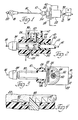
- FIG. 1 is a side elevational view of a preferred embodiment of the subject invention;
- FIG. 2 is an enlarged cross-sectional view of a preferred embodiment of the subject invention;
- FIG. 3 is a plan view taken substantially along line 3-3 of FIG. 2 but partially broken away in cross section; and
- FIG. 4 is an enlarged fragmentary corss-sectional view showing the configuration of the coacting ratcheting teeth.
- A motion transmitting remote control assembly constructed in accordance with the subject invention is generally shown at 10.
- The assembly 10 includes a
flexible conduit 12. Theconduit 12 is preferably of the well-known type including an inner tubular member made of organic polymeric material and surrounded by a plurality of long lay wires disposed helically thereabout with a casing of organic polymeric material disposed about the long lay wires and about the inner tubular member. A fitting 14 is attached to one end of theconduit 12 and is adapted by a flange with a hole therein for attaching the conduit to a support structure, such as the body of a vehicle. - A flexible motion-transmitting
core element 16 is movably supported by theconduit 12 with the ends of the core element extending from the ends of the conduit. The motion-transmittingcore element 16 is a wire member, as illustrated, but also may comprise metal strands helically wound together in cable-like fashion. A coupling member orterminal 18 is disposed upon the end of the core element for attachment of the core element to an operated or operating member. Aslug 20 retains theterminal member 18 upon the core element. The opposite end of thecore element 16 may include a similar terminal as that shown at 18. Theterminal member 18 is slidable along thecore element 16 and includes a pocket for receiving the head of a pin, or the like, extending from an operated or operating member. - The assembly also includes a
support member 22 adapted for attachment to a support structure such as the supportingbracket 24 shown in phantom in FIGS. 1 and 2. Thesupport member 22 is adapted for attachment to a support structure by snap-inmeans 26. The snap-in means 26 are inserted through an opening in a support member such as thebracket 24 to retain thesupport member 22 attached to thesupport bracket 24. Adjacent the snap-in means 26 is aflange 28 which forms a part of thesupport member 22. The snap-in means 26 may be of the type forming the subject matter of U.S. Pat. No. 3,427,894, granted to August E. Tschanz on February 18, 1969, and assigned to the assignee of the subject invention. - The
support member 22 includes a passageway 30 extending therethrough. Theconduit 12 includes aslider member 32 slidably supported in the passageway 30. Theslider member 32 is preferably of a rigid organic polymeric material molded about the plastic exterior of theconduit 12. Theslider member 32 may take the configuration of the slider member specifically disclosed and described in U.S. Pat. No. 4,175,450, granted November 27, 1979, to William G. Bennett and assigned to the assignee of the subject invention. A swivelling dust cover and/orcore wiper 34 is supported through a swivel socket on the end of theslider member 32. - The
support member 22 also includes aguideway 36 extending transversely to the passageway 30 and through thesupport member 22. - The assembly also includes locking means comprising a
latch member 38 engageable with theslider member 32 of the conduit for controlling the longitudinal movement of the conduit relative to thesupport member 22.. Thelatch member 38 is movably supported in theguideway 36 and has anaperture 40 therethrough with theslider member 32 extending through theaperture 40. Thelatch member 38 is L-shaped with theaperture 40 in one leg and the upper horizontally extending leg being .disposed within and surrounded by aprotective wall 42 which is integral with thesupport member 22. Thewall 42 prevents inadvertent contact with thelatch member 38. - The assembly also includes biasing means comprising the
coil spring 44 reacting between thesupport member 22 and the upper leg of thelatch member 38 for urging the latch member into engagement with theslider member 32 of the conduit while allowing thelatch member 38 to be moved out of engagement withslider member 32 in response to a predetermined force. The lower end of thespring 44 is disposed within a cavity in thesupport member 22 while its upper end engages the upper leg of thelatch member 38. - The assembly is characterized by coacting means disposed on the locking means or
member 38 andslider member 32 of theconduit 12 for automatically allowing theconduit 12 to move longitudinally relative to thesupport member 22 in response to a predetermined longitudinal force applied to theconduit 12 through thecore element 16 whereby the distance the core element extends from the conduit is adjusted. The coacting means includes ratcheting means comprising first 46 and second 47 pluralities of teeth on theslider member 32 and one ormore teeth 48 defined by the lower edge of theaperture 40 in thelatch member 38 for automatically allowing theconduit 12 to move longitudinally relative to thesupport member 22 in response to a predetermined longitudinal force applied to the conduit through the core element whereby the distance the core element extends from the conduit may be adjusted. As explained above, in certain situations where tension is placed upon thecore element 16, a force will be applied to the conduit when in a tortuous path urging the conduit to shorten in length between its supports and in such a situation theslider member 32 will ratchet forwardly to an adjusted position. In addition, of course, thelatch member 38 may be manually urged against thespring 44 to manually adjust the effective length of theconduit 12. Specifically, theteeth support member 22 while engaged by thelatch member 38 and preventing such movement in the opposite direction while engaged by thelatch member 38 thereby effecting automatic ratcheting adjustment in the effective length of the conduit. - The ratcheting
teeth conduit 12 which is less in magnitude than a second degree of resistance to subsequent longitudinal movement of theconduit 12 so that a lesser force applied to thecore element 16 is required for a predetermined length of initial movement of theconduit 12 relative to thesupport member 22 than the greater force applied to thecore element 16 required for such relative movement after the initial predetermined length of movement. The first plurality ofteeth 46 provide less resistance to movement of theteeth 48 of the lockingmember 38 thereover than the resistance to such movement of the locking member provided by the second plurality ofteeth 47. This is specifically accomplished by the first plurality ofteeth 46 having ramps of lesser slope (degree of slant or total depth) than the ramps of the second plurality ofteeth 47. In addition, each of theteeth - As fully set forth in the above-mentioned patent 4,331,041, the assembly also includes a temperature-responsive means comprising an
elongated slug 50 reacting between thesupport member 22 and the upper leg of thelatch member 38 in parallel with thespring 44 for . allowing movement of thelatch member 38 in response to a predetermined force in a predetermined temperature range and for requiring higher forces to move thelatch member 38 than the predetermined force at temperatures out of the predetermined temperature range. - All of the components except the
core element 16 and thelatch 38 and thespring 44 are preferably made of organic polymeric or plastic materials. - The invention has been described in an illustrative manner, and it is to be understood that the terminology which has been used is intended to be in the nature of words of description rather than of limitation.
- Obviously, may modifications and variations of the present invention are possible in light of the above teachings. It is, therefore, to be understood that within the scope of the appended claims wherein reference numerals are merely for convenience and are not to be in any way limiting, the invention may be practiced otherwise than as specifically described, and the invention provides any novel feature or concept or novel combination of same as disclosed herein.
Claims (9)
- The embodiments of the invention in which an exclusive property or privilege is claimed are defined as follows:
- 1. A motion transmitting remote control assembly (10) of the type for transmitting motion along a curved path by a flexible motion transmitting core element (16), said assembly comprising; a flexible conduit (12) having opposite ends; a flexible motion transmitting core element (16) movably supported by said conduit (12) with the ends thereof extending from the ends of said conduit, a support member (22), locking means (38) engageable with said conduit for controlling the longitudinal movement thereof relative to said support member, biasing means (44) reacting between said support member (22) and said locking means (38) for urging said locking means into engagement with said conduit while allowing said locking means to be moved out of engagement with said conduit in response to a predetermined force, coacting means (46, 47, 48) disposed on said locking means (30) and said conduit (12, 32) respectively for automatically allowing said conduit (12, 32) to move longitudinally relative to said support member (22) in response to a predetermined longitudinal force applied to said conduit through said core element (16) whereby the distance said core element (16) extends from said conduit is adjusted, said assembly characterized by said coacting means including ratcheting means (46, 47, 48) for providing a first degree of resistance to initial longitudinal movement of said conduit which is less in magnitude than a second degree of resistance to subsequent longitudinal movement of said conduit so that a lesser force applied to said core element is required for a predetermined length of initial movement of said conduit relative to said support member than the greater force applied to said core element required for such relative movement after the initial predetermined length of movement.
- 2. An assembly as set forth in claim 1 further characterized by said coacting ratcheting means comprising first (46) and second (47) pluralities of teeth along said conduit (12, 32), said first plurality of teeth (46) providing less resistance to movement of said locking means (38) thereover than the resistance thereto provided by said second plurality of teeth (47).
- 3. An assembly as set forth in claim 2 further characterized by said first plurality of teeth (46) having ramps of lesser slope than the ramps of said second plurality of teeth (47).
- 4. An assembly as set forth in claim 3 further characterized by each of said first (46) and second (47) pluralities of teeth aligned one after the other and having equal individual dimensions longitudinally of said conduit.
- 5. An assembly as set forth in claim 4 wherein said biasing means comprises a coil spring (44) disposed between said support means (22) and said locking means (38) to be placed in tension.
- 6. An assembly as set forth in claim 5 wherein said support member (22) includes a passageway (30) extending therethrough, said conduit (12) including a slider member (32) slidably supported in said passageway- (30), said support member (32) including a guideway (36) extending transversely to said passageway (30) and through said support member (22), said locking means comprising a latch member (38) movably supported in said guideway (36) and having an - aperture (40) therethrough with said slider member (32) extending through said aperture '(40), said first (46) and second (47) pluralities of teeth being disposed on said slider member (32) and said coacting means including a tooth (48) defined by the lower edge of said aperture (40) in said latch member (38), said latch member (38) being L-shaped with said spring (44) engaging . one leg and said aperture (40) being on the opposite leg thereof.
- 7. An assembly as set forth in claim 6 wherein said tooth (48) on said latch member (38) and said teeth (46, 47) on said slider member (32) are sloped to present abutments for preventing relative longitudinal movement between said slider member (32) and said support member (22) on the direction opposite to said direction of initial movement at said lesser degree of resistance.
- 8. An assembly as set forth in claim 7 including temperature-responsive means (50) disposed in parallel with said coil spring (44) for applying different forces to said locking member (38) at different temperatures.
Applications Claiming Priority (2)
| Application Number | Priority Date | Filing Date | Title |
|---|---|---|---|
| US06/675,639 US4610180A (en) | 1984-11-28 | 1984-11-28 | Motion transmitting remote control assembly--initial reduced resistance self-adjust |
| US675639 | 1984-11-28 |
Publications (2)
| Publication Number | Publication Date |
|---|---|
| EP0183338A2 true EP0183338A2 (en) | 1986-06-04 |
| EP0183338A3 EP0183338A3 (en) | 1987-04-29 |
Family
ID=24711368
Family Applications (1)
| Application Number | Title | Priority Date | Filing Date |
|---|---|---|---|
| EP85305379A Withdrawn EP0183338A3 (en) | 1984-11-28 | 1985-07-29 | Motion transmitting remote control assembly - initial reduced resistance self-ajust |
Country Status (5)
| Country | Link |
|---|---|
| US (1) | US4610180A (en) |
| EP (1) | EP0183338A3 (en) |
| JP (1) | JPS61130610A (en) |
| KR (1) | KR890000316B1 (en) |
| CA (1) | CA1233092A (en) |
Cited By (4)
| Publication number | Priority date | Publication date | Assignee | Title |
|---|---|---|---|---|
| EP0251582A1 (en) | 1986-06-25 | 1988-01-07 | Gill's Cables Limited | Control cables |
| FR2607202A1 (en) * | 1986-11-26 | 1988-05-27 | Mans Cables | Cable-type mechanical control device |
| US4854185A (en) * | 1988-10-17 | 1989-08-08 | Babcock Industries Inc. | Manually operated and locked conduit length adjuster system |
| DE102012017685A1 (en) * | 2012-07-04 | 2014-01-23 | Johnson Controls Gmbh | Compensation device for Bowden cable, has guide structure located relative to sheath and secured on casing, and locking structure that is provided with tooth and slid relative to guide structure, on which guide structure is fixed |
Families Citing this family (15)
| Publication number | Priority date | Publication date | Assignee | Title |
|---|---|---|---|---|
| US4694706A (en) * | 1986-02-14 | 1987-09-22 | Acco Babcock Inc. | Control cable conduit length adjustment device |
| AU591232B2 (en) * | 1986-02-14 | 1989-11-30 | Acco Babcock Inc. | An adjuster device for a control cable assembly |
| US4842106A (en) * | 1987-10-08 | 1989-06-27 | Hughes Aircraft Company | Rate controllable damping mechanism |
| US4892003A (en) * | 1988-04-27 | 1990-01-09 | Flex Technologies, Inc. | Assembly for the self-adjustment of a cable casing |
| JPH0262415A (en) * | 1988-08-24 | 1990-03-02 | Nippon Cable Syst Inc | Adjusting device for control cable installation position |
| US4887930A (en) * | 1988-11-18 | 1989-12-19 | Babcock Industries Inc. | Manually controlled adjustable locking mechanism for a cable control system |
| US4932503A (en) * | 1988-12-19 | 1990-06-12 | General Motors Corporation | Blind assembly of parking brake cable to parking brake lever |
| JPH02145317U (en) * | 1989-05-15 | 1990-12-10 | ||
| US5142933A (en) * | 1991-05-23 | 1992-09-01 | Teleflex Incorporated | Motion transmitting remote control assembly having conduit length adjuster |
| US5706706A (en) * | 1992-04-06 | 1998-01-13 | Hnk Spring Co., Ltd. | Length-adjusting device for control cable |
| US5295408A (en) * | 1992-10-09 | 1994-03-22 | Nagle Industries, Inc. | Adjustable cable strand end fitting |
| US5489011A (en) * | 1994-06-06 | 1996-02-06 | Chrysler Corporation | Vehicle clutch cable self-adjusting mechanism |
| DE19752028C2 (en) | 1997-11-24 | 1999-09-30 | Siemens Ag | Method for adjusting the valve needle stroke in metering valves and metering valve with valve needle stroke adjusted according to this method |
| US8215202B2 (en) | 2007-06-18 | 2012-07-10 | Grand Rapids Controls Company, Llc | Cable length adjustment mechanism |
| US8593576B2 (en) * | 2009-10-15 | 2013-11-26 | At&T Intellectual Property I, L.P. | Gesture-based remote control |
Citations (4)
| Publication number | Priority date | Publication date | Assignee | Title |
|---|---|---|---|---|
| US3662617A (en) * | 1970-10-08 | 1972-05-16 | Teleflex Inc | Remote control assembly |
| US3710645A (en) * | 1970-10-08 | 1973-01-16 | Teleflex Inc | Remote control assembly |
| US4175450A (en) * | 1978-02-21 | 1979-11-27 | Teleflex Incorporated | Motion transmitting remote control assembly |
| US4331041A (en) * | 1980-02-07 | 1982-05-25 | Teleflex Incorporated | Motion transmitting remote control assembly |
Family Cites Families (4)
| Publication number | Priority date | Publication date | Assignee | Title |
|---|---|---|---|---|
| GB1167532A (en) * | 1966-08-26 | 1969-10-15 | Wright Rain Ltd | Valve Responsive to a Pulsating Fluid Pressure |
| US3572160A (en) * | 1969-06-12 | 1971-03-23 | Teleflex Inc | Motion transmitting remote control assembly |
| US3587341A (en) * | 1970-01-26 | 1971-06-28 | Theodore E Fiddler | Actuator cable adjustment device |
| US3665784A (en) * | 1970-10-08 | 1972-05-30 | Teleflex Inc | Remote control assembly |
-
1984
- 1984-11-28 US US06/675,639 patent/US4610180A/en not_active Expired - Lifetime
-
1985
- 1985-07-23 CA CA000487311A patent/CA1233092A/en not_active Expired
- 1985-07-29 EP EP85305379A patent/EP0183338A3/en not_active Withdrawn
- 1985-08-07 KR KR1019850005693A patent/KR890000316B1/en active IP Right Grant
- 1985-08-21 JP JP60183797A patent/JPS61130610A/en active Pending
Patent Citations (4)
| Publication number | Priority date | Publication date | Assignee | Title |
|---|---|---|---|---|
| US3662617A (en) * | 1970-10-08 | 1972-05-16 | Teleflex Inc | Remote control assembly |
| US3710645A (en) * | 1970-10-08 | 1973-01-16 | Teleflex Inc | Remote control assembly |
| US4175450A (en) * | 1978-02-21 | 1979-11-27 | Teleflex Incorporated | Motion transmitting remote control assembly |
| US4331041A (en) * | 1980-02-07 | 1982-05-25 | Teleflex Incorporated | Motion transmitting remote control assembly |
Cited By (5)
| Publication number | Priority date | Publication date | Assignee | Title |
|---|---|---|---|---|
| EP0251582A1 (en) | 1986-06-25 | 1988-01-07 | Gill's Cables Limited | Control cables |
| FR2607202A1 (en) * | 1986-11-26 | 1988-05-27 | Mans Cables | Cable-type mechanical control device |
| US4854185A (en) * | 1988-10-17 | 1989-08-08 | Babcock Industries Inc. | Manually operated and locked conduit length adjuster system |
| DE102012017685A1 (en) * | 2012-07-04 | 2014-01-23 | Johnson Controls Gmbh | Compensation device for Bowden cable, has guide structure located relative to sheath and secured on casing, and locking structure that is provided with tooth and slid relative to guide structure, on which guide structure is fixed |
| DE102012017685B4 (en) * | 2012-07-04 | 2016-03-10 | Johnson Controls Gmbh | Compensation device for a Bowden cable |
Also Published As
| Publication number | Publication date |
|---|---|
| EP0183338A3 (en) | 1987-04-29 |
| KR890000316B1 (en) | 1989-03-14 |
| KR860004256A (en) | 1986-06-20 |
| US4610180A (en) | 1986-09-09 |
| CA1233092A (en) | 1988-02-23 |
| JPS61130610A (en) | 1986-06-18 |
Similar Documents
| Publication | Publication Date | Title |
|---|---|---|
| US4610180A (en) | Motion transmitting remote control assembly--initial reduced resistance self-adjust | |
| US4331041A (en) | Motion transmitting remote control assembly | |
| US4175450A (en) | Motion transmitting remote control assembly | |
| US4841806A (en) | Self-adjust mini increment | |
| CA1277211C (en) | Remote control balanced adjust system | |
| US5178034A (en) | Automatic adjust assembly with release pin | |
| US4177691A (en) | Motion transmitting remote control assembly | |
| US3572159A (en) | Motion transmitting remote control assembly | |
| EP0242965B1 (en) | Remote control levered self adjust actuator | |
| US4658668A (en) | Transmission kickdown cable adjuster | |
| US3710645A (en) | Remote control assembly | |
| US4869123A (en) | Cable length self-locking adjustment device | |
| US5709132A (en) | Cable length adjustment mechanism | |
| US7530288B2 (en) | Automatic adjust assembly with release lock | |
| US5570612A (en) | Core adjust with sliding rear spring cover | |
| GB2253250A (en) | A gearchange lever comprising lever parts connected by a deformable bar | |
| EP0221627B1 (en) | Self-adjust mini increment | |
| EP0281705A1 (en) | Parklock control | |
| US3572160A (en) | Motion transmitting remote control assembly | |
| EP0448195A1 (en) | A motion transmitting remote control assembly and method for making same | |
| JPS62261709A (en) | Manual adjusting core element terminal device | |
| EP0251582A1 (en) | Control cables | |
| US20030005789A1 (en) | C-shaped pin-connector with retaining ramp |
Legal Events
| Date | Code | Title | Description |
|---|---|---|---|
| PUAI | Public reference made under article 153(3) epc to a published international application that has entered the european phase |
Free format text: ORIGINAL CODE: 0009012 |
|
| AK | Designated contracting states |
Kind code of ref document: A2 Designated state(s): AT BE CH DE FR GB IT LI LU NL SE |
|
| PUAL | Search report despatched |
Free format text: ORIGINAL CODE: 0009013 |
|
| AK | Designated contracting states |
Kind code of ref document: A3 Designated state(s): AT BE CH DE FR GB IT LI LU NL SE |
|
| 17P | Request for examination filed |
Effective date: 19870325 |
|
| 17Q | First examination report despatched |
Effective date: 19880629 |
|
| STAA | Information on the status of an ep patent application or granted ep patent |
Free format text: STATUS: THE APPLICATION IS DEEMED TO BE WITHDRAWN |
|
| 18D | Application deemed to be withdrawn |
Effective date: 19890202 |
|
| RIN1 | Information on inventor provided before grant (corrected) |
Inventor name: SPEASE, ARTHUR L. |