EP0183263A2 - Fire extinguisher valve with pressure indicator - Google Patents
Fire extinguisher valve with pressure indicator Download PDFInfo
- Publication number
- EP0183263A2 EP0183263A2 EP85115098A EP85115098A EP0183263A2 EP 0183263 A2 EP0183263 A2 EP 0183263A2 EP 85115098 A EP85115098 A EP 85115098A EP 85115098 A EP85115098 A EP 85115098A EP 0183263 A2 EP0183263 A2 EP 0183263A2
- Authority
- EP
- European Patent Office
- Prior art keywords
- valve stem
- passageway
- disposed
- dispensing apparatus
- pressure
- Prior art date
- Legal status (The legal status is an assumption and is not a legal conclusion. Google has not performed a legal analysis and makes no representation as to the accuracy of the status listed.)
- Withdrawn
Links
Images

Classifications
-
- F—MECHANICAL ENGINEERING; LIGHTING; HEATING; WEAPONS; BLASTING
- F17—STORING OR DISTRIBUTING GASES OR LIQUIDS
- F17C—VESSELS FOR CONTAINING OR STORING COMPRESSED, LIQUEFIED OR SOLIDIFIED GASES; FIXED-CAPACITY GAS-HOLDERS; FILLING VESSELS WITH, OR DISCHARGING FROM VESSELS, COMPRESSED, LIQUEFIED, OR SOLIDIFIED GASES
- F17C13/00—Details of vessels or of the filling or discharging of vessels
- F17C13/02—Special adaptations of indicating, measuring, or monitoring equipment
- F17C13/025—Special adaptations of indicating, measuring, or monitoring equipment having the pressure as the parameter
-
- A—HUMAN NECESSITIES
- A62—LIFE-SAVING; FIRE-FIGHTING
- A62C—FIRE-FIGHTING
- A62C37/00—Control of fire-fighting equipment
- A62C37/50—Testing or indicating devices for determining the state of readiness of the equipment
-
- F—MECHANICAL ENGINEERING; LIGHTING; HEATING; WEAPONS; BLASTING
- F17—STORING OR DISTRIBUTING GASES OR LIQUIDS
- F17C—VESSELS FOR CONTAINING OR STORING COMPRESSED, LIQUEFIED OR SOLIDIFIED GASES; FIXED-CAPACITY GAS-HOLDERS; FILLING VESSELS WITH, OR DISCHARGING FROM VESSELS, COMPRESSED, LIQUEFIED, OR SOLIDIFIED GASES
- F17C2205/00—Vessel construction, in particular mounting arrangements, attachments or identifications means
- F17C2205/03—Fluid connections, filters, valves, closure means or other attachments
- F17C2205/0302—Fittings, valves, filters, or components in connection with the gas storage device
- F17C2205/0323—Valves
- F17C2205/0329—Valves manually actuated
-
- F—MECHANICAL ENGINEERING; LIGHTING; HEATING; WEAPONS; BLASTING
- F17—STORING OR DISTRIBUTING GASES OR LIQUIDS
- F17C—VESSELS FOR CONTAINING OR STORING COMPRESSED, LIQUEFIED OR SOLIDIFIED GASES; FIXED-CAPACITY GAS-HOLDERS; FILLING VESSELS WITH, OR DISCHARGING FROM VESSELS, COMPRESSED, LIQUEFIED, OR SOLIDIFIED GASES
- F17C2205/00—Vessel construction, in particular mounting arrangements, attachments or identifications means
- F17C2205/03—Fluid connections, filters, valves, closure means or other attachments
- F17C2205/0388—Arrangement of valves, regulators, filters
- F17C2205/0394—Arrangement of valves, regulators, filters in direct contact with the pressure vessel
-
- F—MECHANICAL ENGINEERING; LIGHTING; HEATING; WEAPONS; BLASTING
- F17—STORING OR DISTRIBUTING GASES OR LIQUIDS
- F17C—VESSELS FOR CONTAINING OR STORING COMPRESSED, LIQUEFIED OR SOLIDIFIED GASES; FIXED-CAPACITY GAS-HOLDERS; FILLING VESSELS WITH, OR DISCHARGING FROM VESSELS, COMPRESSED, LIQUEFIED, OR SOLIDIFIED GASES
- F17C2250/00—Accessories; Control means; Indicating, measuring or monitoring of parameters
- F17C2250/04—Indicating or measuring of parameters as input values
- F17C2250/0404—Parameters indicated or measured
- F17C2250/043—Pressure
-
- F—MECHANICAL ENGINEERING; LIGHTING; HEATING; WEAPONS; BLASTING
- F17—STORING OR DISTRIBUTING GASES OR LIQUIDS
- F17C—VESSELS FOR CONTAINING OR STORING COMPRESSED, LIQUEFIED OR SOLIDIFIED GASES; FIXED-CAPACITY GAS-HOLDERS; FILLING VESSELS WITH, OR DISCHARGING FROM VESSELS, COMPRESSED, LIQUEFIED, OR SOLIDIFIED GASES
- F17C2250/00—Accessories; Control means; Indicating, measuring or monitoring of parameters
- F17C2250/06—Controlling or regulating of parameters as output values
- F17C2250/0605—Parameters
- F17C2250/0636—Flow or movement of content
-
- F—MECHANICAL ENGINEERING; LIGHTING; HEATING; WEAPONS; BLASTING
- F17—STORING OR DISTRIBUTING GASES OR LIQUIDS
- F17C—VESSELS FOR CONTAINING OR STORING COMPRESSED, LIQUEFIED OR SOLIDIFIED GASES; FIXED-CAPACITY GAS-HOLDERS; FILLING VESSELS WITH, OR DISCHARGING FROM VESSELS, COMPRESSED, LIQUEFIED, OR SOLIDIFIED GASES
- F17C2270/00—Applications
- F17C2270/07—Applications for household use
- F17C2270/0754—Fire extinguishers
-
- Y—GENERAL TAGGING OF NEW TECHNOLOGICAL DEVELOPMENTS; GENERAL TAGGING OF CROSS-SECTIONAL TECHNOLOGIES SPANNING OVER SEVERAL SECTIONS OF THE IPC; TECHNICAL SUBJECTS COVERED BY FORMER USPC CROSS-REFERENCE ART COLLECTIONS [XRACs] AND DIGESTS
- Y10—TECHNICAL SUBJECTS COVERED BY FORMER USPC
- Y10S—TECHNICAL SUBJECTS COVERED BY FORMER USPC CROSS-REFERENCE ART COLLECTIONS [XRACs] AND DIGESTS
- Y10S116/00—Signals and indicators
- Y10S116/17—Tactile
Definitions
- the present invention relates to valve mechanisms for controlling the discharge of material under pressure from a container.
- the invention relates to discharge valves for fire extinguishers.
- the object of the invention is to provide a dispensing apparatus which avoids the disadvantages of prior device while affording additional structural and operating,advantages.
- the present invention provides a dispensing apparatus for controlling the discharge of material under pressure from a container outlet, including a nozzle and a passageway providing communication between the container outlet and the nozzle, and a valve seat in the passageway, characterized by an elongated tubular valve stem disposed in the passageway and having an actuating end projecting from the passageway, seal means carried by said valve stem said valve stem being movable axially of the passageway, bias means resient- ly urging said valve stem to a closed condition wherein said seal means is disposed in sealing engagement with the valve seat said valve stem being responsive to an external force on said actuating end thereof for movement to an open condition wherein said valve stem and said seal means are spaced from said valve seat and elongated indicating means shorter than said valve stem and disposed therewithin for movement axially with respect thereto, said indicating means having an inner end disposed at all times within said valve stem and an outer end, said indicating means being responsive to pressure in the container for movement to extended positions with said outer end extending
- the dispensing apparatus of this invention has with pressure indicating means which is of relatively simple, economical and compact construction.
- a fire extinguisher generally designated by the numeral 10,.
- a container 11 for holding fire extinguishing material under pressure.
- the fire extinguishing material is a dry chemical extinguisher comprising a dry powder and a pressurized impelling gas for expelling the powder from the container.
- the present invention could be used with other types of fire extinguishing materials.
- the continer 11 includes a bottle-shaped shell 12 having an internally threaded neck 13 at one end thereof coaxial therewith defining a circular outlet opening. Disposed in the shell 12 coaxially therewith is an elongated siphon tube 14, the upper end of which is received in a cylindrical adapter 15. More particularly, the adapter 15 has a cylindrical bore 16 extending axially therethrough, having at its inner end a counterbore portion defining an annular shoulder 17 against which the distal end of the siphon tube 14 is seated. Integral with the adapter 15 at its inner end and extending radially outwardly therefrom is an annular flange 18. Integral with the outer end of the adapter 15 is a cylindrical lip 19 disposed in surrounding relationship with the outer end of the bore 16. Preferably, the upper end of the siphon tube 14 is press- fitted into the adapter 15.
- the adapter 15 is carried by a dispenser assembly 20 which includes an elongated housing 21 having an externally threaded cylindrical attachment portion at one end thereof disposed for threaded engagement in the neck 13 of the container 11.
- the housing 21 carries a flange 22a engageable with the distal end of the neck 13 to limit the depth of insertion of the attachment portion 22 therein, a resilient seal ring 23 being disposed between the neck 13 and the flange 22a for providing a fluid-tight seal therebetween.
- a handle 24 projects laterally from the side of the housing 21.
- a generally cylindrical bore or passageway 25 Extending longitudinally through the housing 21 and the attachment portion 22 thereof is a generally cylindrical bore or passageway 25.
- the adapter 15 is dimensioned to be received in the inner end of the passageway 25, with the flange 18 abutting against the inner end of the attachment portion 22 and secured thereto by suitable means.
- the inner surface of the passageway 25 has a frustoconical portion intermediate the ends thereof defining a valve seat 26.
- the portion 27 of the passageway 25 disposed outwardly beyond the valve seat 26 has walls which coverage toward the outer end of the passageway 25 where it exits the outer end of the housing 21.
- the housing 21 includes a nozzle portion 28 which is integral therewith and projects laterally therefrom adjacent to the outer end thereof, and which has a nozzle bore 29 therethrough which communicates with the outer portion 27 of the passageway 25.
- the outer end of the passageway 25 communicates with an irregular lever recess 30 formed in the outer end of the housing 21.
- an actuating lever 31 Disposed in the recess 30 is an actuating lever 31, which has one end thereof pivotally connected to the housing 21 in a manner described below for pivotal movement between a normal rest position, illustrated in Figure 2, and an actuating position, illustrated in Figure 3.
- the actuating lever 31 is provided with a concave, part-spherical portion 33 intermediate its ends, overlying the outer end of the passageway 25, and having an elongated aperture 34 therein.
- a hole 35 which is adapted for coaxial alignment with like holes 36 in the housing 21 for receiving a safety pin (not shown), for holding the actuating lever 31 in its normal rest position and preventing movement thereof to the actuating position.
- the pivoted end of the actuating lever 31 is bifurcated, defining a pair of elongated, laterally flexible and resilient arms 37.
- Each of the arms 37 is provided adjacent to its distal end with a laterally outwardly extending pivot lug 38, the lugs 38 being disposed to be respectively received in complementary bores 38a in the side walls of the lever recess 30 for pivotal mounting of the actuating lever 31.
- the actuating lever 31 is also provided with an elongated, flexible retaining member 39 which extends between the arms 37 generally parallel thereto and having a lateral width so as substantially to occupy the space between the arms 37.
- the retaining member 39 is deflected downwardly or upwardly from between the arms 37 and the arms 37 are squeezed together to permit the pivot lugs 38 to be aligned with the bores 38a.
- the arms 37 are then released to seat the lugs 38 in the bores 38a and the retaining member 39 is then released to return to its rest position between the arms 37.
- the retaining member 39 will prevent the arms 37 from being accidentally moved back together, thereby to prevent accidental dislodgement of the actuating lever 31, such as in the event that the container 11 is dropped.
- valve assembly 40 Disposed within the housing 21 is a valve assembly 40, which includes an elongated tubular valve stem 41 disposed coaxially within the passageway 25 for movement axially with respect thereto.
- the outer surface of the valve stem 41 has a frustoconical seal portion 42 intermediate its ends.
- Formed in the seal portion 42 is a circumferential groove 43 which receives therein a resilient O-ring seal 44 disposed for fluid-tight sealing engagement with the valve seat 26 when the valve stem 41 is disposed in a closed condition, illustrated in Figure 2.
- the outer end of the valve stem 41 projects a predetermined distance outwardly beyond the outer end of the passageway 25 for engagement with the concave portion 33 of the actuating lever 31 in the rest position thereof.
- the inner end of the valve stem 41 is provided with four equiangularly spaced-apart, radially outwardly extending fins 45, each of which is provided with a groove 46 adjacent to its inner end. Seated in the grooves 46 is one end of a helical compression spring 47, the other end of which is seated against the outer end of the adapter 15 in surrounding relationship with the cylindrical lip 19, for resiliently urging the valve stem 41 toward its closed condition.
- a bore 50 having a central cylindrical portion 51 which is joined by an annular shoulder 52 to a reduced-diameter cylindrical portion 53.
- the inner end of the cylindrical portion 51 joins a frustoconical portion 54, which in turn joins a frustoconical entry portion 55 at the inner end of the valve stem 41.
- the outer end of the reduced-diameter cylindrical portion 53 is joined by an annular shoulder 56 to an elongated tapered portion 57, which is generally frustoconical and converges toward the outer end of the valve stem 41, exiting the valve stem 41 at a concave end face 58 which is shaped substantially complementary to the concave portion 33 of the actuating lever 31.
- the fins 45 on the valve stem 41 minimize the radial movement of the valve stem 41 relative to the passageway 25.
- an elongated cylindrical indicator rod 60 Disposed coaxially within the bore 50 is an elongated cylindrical indicator rod 60, having a length less than that of the valve stem 41.
- the indicator rod 60 has an enlarged-diameter inner end 61 disposed for sliding engagement with the wall of the cylindrical portion 51 of the bore 50, the enlarged end 61 having a frustoconical outer surface 62.
- an annular flange 63 is integral with the indicator rod 60 and extending radially outwardly there-from a slight distance from the enlarged end 61.
- the flange 63 has an outer diameter substantially equal to that of the enlarged end 61 and cooperates therewith to define therebetween an annular groove 64, in which is received a resilient O-ring seal 65 for fluid-tight sealing engagement with the cylindrical portion 51 of the bore 50.
- a helical compression spring 67 Disposed in surrounding relationship with the indicator rod 60 and trapped between the flange 63 and the shoulder 56 in the reduced-diameter portion 53 of the bore 50 is a helical compression spring 67, which resiliently urges the indicator rod 60 toward a retracted position, illustrated in broken line in Figure 3.
- the flange 63 is engageable with the shoulder 52 for limiting the axial outward movement of the indicator rod 60 in its fully extended position, illustrated in solid line in the drawings, wherein the outer end of the indicator rod 60 projects a predetermined distance outwardly beyond the end face 58 of the valve stem 41.
- the parts are arranged so that the projecting portion of the indicator rod 60 extends outwardly through the slot 34 in the actuating lever 31 for access by a user, as will be explained more fully below.
- the passageway 25 communicates with the siphon tube 14 and is, therefore, exposed to the internal pressure within the container 11.
- This pressure acts on the valve stem 41 and, particularly, the seal portion 42 thereof, below the 0-ring 44, as well as on the O-ring 44, for urging the valve stem 41 outwardly and holding it in its closed condition, illustrated in Figure 2.
- the flow of extinguishing material to the nozzle bore 29 is blocked by the fluid-tight seal formed by the O-ring seal 44 between the seal portion 42 and the valve seat 26.
- the fluid-tight seal formed by the O-ring seal 65 between the indicator rod 60 and the valve stem 41 prevents the flow of extinguishing material between the indicator rod 60 and the valve stem 41. This pressure also holds the indicator rod 60 in its extended position.
- the safety pin When it is desired to use the fire ex- tinsuisher 10, the safety pin is pulled and the actuating lever 31 is manually depressed to the actuating position, illustrated in Figure 3, for driving the valve stem 41 inwardly to its open condition, illustrated in Figure 3, wherein the seal portion 42 thereof is spaced from the valve seat 26 to permit the flow of extinguishing material from the siphon tube 14, around the valve stem 41 and outwardly through the nozzle bore 29.
- the position of the indicator rod 60 relative to the valve stem 41 does not change during this movement of the valve stem 41 to its open condition.
- the actuating lever 31 After the extinguishing is completed, the actuating lever 31 is released and the valve stem 41 is returned to its closed position, either under the action of the pressure within the container 11 or, if the remaining pressure is insufficient, under the action of the spring 47.
- the indicator rod 60 permits the user to test the pressure in the container 11.
- the indicator rod 60 is manually depressed by the usuer's thumb to a retracted or withdrawn position, illustrated in broken line in Figure 3, against the urging of the pressure in the container 11. If the pressure within the container 11 is adequate for use, it will return the indicator rod 60 to its fully extended position. If the pressure is inadequate, it will not be sufficient to overcome the force of the bias spring 67 and, accordingly, the indicator rod 60 will remain in its depressed or withdrawn position or will not fully return to its extended position.
- the valve stem 41 and the indicator rod 60 are each of unitary, one-piece construction, thereby serving to minimize the number of parts in the dispenser assembly 20 and to simplify fabrication.
- the diameter of the indicator rod 60 may be such that it is disposed in sliding engagement around the entire circumference thereof with the valve stem 41 at the outer end of the tapered portion 57 of the bore 50.
- the outer diameter of the valve stem 41 is such that it is disposed in sliding engagement around the entire circumference thereof with the housing 21 at the outer end of the passageway 25. This engagement provides a partial seal which is sufficient to prevent the escape of extinguishing material from the outer end of the passageway 25 when the fire extinguisher 10 is in use, thereby obviating the use of a separate seal member at this location.
- the inner end of the indicator rod 60 is at all times disposed well within the bore 50.
- the indicator rod 60 does not necessitate any extension of the length of the valve stem 41 or the dispenser assembly 20.
- the bias springs 47 and 67 and the seal members 44 and 65 are all disposed within the passageway 25 between the adapter 15 and the nozzle portion 28, none of these parts being exposed in use.
- the bias springs 47 and 67 are preferably made of stainless steel, the 0-ring seals 44 and 65 and made of any suitable material approved by Underwriters Laboratories for use with dry chemical extinguishers;
- the siphon tube 14 may be formed of a rigid polypropylene material;
- the housing 21 and the actuating lever 31 may be formed of nylon;
- the adapter 15, the valve stem 41 and the indicator rod 60 may be formed of an acetal copolymer, such as that sold by Celanese Plastics & Specialties Co. under the trademark "CELCON".
- an improved dispenser assembly for a pressurized container which also affords a pressure indication, the assembly being characterized by a simple and economical construction and a minimal number of parts, most of which are completely protected and non-exposed in use, the assembly being of compact construction.
Abstract
Description
- The present invention relates to valve mechanisms for controlling the discharge of material under pressure from a container. In particular, the invention relates to discharge valves for fire extinguishers.
- There are present in the prior art many container closures and dispensing devices designed to operate with fluids or free-flowing powders which are under pressure, such as fire extinguishers. Such dispensing devices have also been provided with pressure indicating means to give an indication of the pressure within the container so that a user can tell whether the container needs to be repressurized or refilled. However, such prior dispensing devices with pressure indicators are typically of complex construction, comprising a large number of parts. In many cases some of these parts or portions thereof are exposed in use, so as to be subject to the environment in which the fire extinguisher is used or stored. Furthermore, in those devices in which the indicating means forms a part of the valve mechanism, it typically entails elongation of the valve mechanism and, therefore, the housing thereof, thereby increasing the overall size of the extinguisher.
- The object of the invention is to provide a dispensing apparatus which avoids the disadvantages of prior device while affording additional structural and operating,advantages.
- The present invention provides a dispensing apparatus for controlling the discharge of material under pressure from a container outlet, including a nozzle and a passageway providing communication between the container outlet and the nozzle, and a valve seat in the passageway, characterized by an elongated tubular valve stem disposed in the passageway and having an actuating end projecting from the passageway, seal means carried by said valve stem said valve stem being movable axially of the passageway, bias means resient- ly urging said valve stem to a closed condition wherein said seal means is disposed in sealing engagement with the valve seat said valve stem being responsive to an external force on said actuating end thereof for movement to an open condition wherein said valve stem and said seal means are spaced from said valve seat and elongated indicating means shorter than said valve stem and disposed therewithin for movement axially with respect thereto, said indicating means having an inner end disposed at all times within said valve stem and an outer end, said indicating means being responsive to pressure in the container for movement to extended positions with said outer end extending from said actuating end of said valve stem a distance which varies with the pressure.
- The dispensing apparatus of this invention has with pressure indicating means which is of relatively simple, economical and compact construction.
- In the drawings:
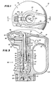
- Figure 1 is a fragmentary top plan view of a fire extinguisher incorporating a dispensing apparatus constructed in accordance with and embodying the features of the present invention;
- Figure 2 is an enlarged, fragmentary view in vertical section taken along the line 2-2 in Figure 1, illustrating the valve assembly of the dispensing apparatus in its normal closed condition; and
- Figure 3 is a fragmentary view similar to Figure 2, illustrating the valve assembly in its open condition and illustrating operation of the pressure indicating means.
- There is illustrated in the drawings a fire extinguisher, generally designated by the
numeral 10,. including a container 11 for holding fire extinguishing material under pressure. Preferably, the fire extinguishing material is a dry chemical extinguisher comprising a dry powder and a pressurized impelling gas for expelling the powder from the container. However, it will be appreciated that the present invention could be used with other types of fire extinguishing materials. - The continer 11 includes a bottle-
shaped shell 12 having an internally threadedneck 13 at one end thereof coaxial therewith defining a circular outlet opening. Disposed in theshell 12 coaxially therewith is anelongated siphon tube 14, the upper end of which is received in acylindrical adapter 15. More particularly, theadapter 15 has acylindrical bore 16 extending axially therethrough, having at its inner end a counterbore portion defining anannular shoulder 17 against which the distal end of thesiphon tube 14 is seated. Integral with theadapter 15 at its inner end and extending radially outwardly therefrom is anannular flange 18. Integral with the outer end of theadapter 15 is acylindrical lip 19 disposed in surrounding relationship with the outer end of thebore 16. Preferably, the upper end of thesiphon tube 14 is press- fitted into theadapter 15. - The
adapter 15 is carried by adispenser assembly 20 which includes anelongated housing 21 having an externally threaded cylindrical attachment portion at one end thereof disposed for threaded engagement in theneck 13 of the container 11. Thehousing 21 carries aflange 22a engageable with the distal end of theneck 13 to limit the depth of insertion of theattachment portion 22 therein, aresilient seal ring 23 being disposed between theneck 13 and theflange 22a for providing a fluid-tight seal therebetween. Ahandle 24 projects laterally from the side of thehousing 21. - Extending longitudinally through the
housing 21 and theattachment portion 22 thereof is a generally cylindrical bore orpassageway 25. Theadapter 15 is dimensioned to be received in the inner end of thepassageway 25, with theflange 18 abutting against the inner end of theattachment portion 22 and secured thereto by suitable means. The inner surface of thepassageway 25 has a frustoconical portion intermediate the ends thereof defining avalve seat 26. Theportion 27 of thepassageway 25 disposed outwardly beyond thevalve seat 26 has walls which coverage toward the outer end of thepassageway 25 where it exits the outer end of thehousing 21. Thehousing 21 includes anozzle portion 28 which is integral therewith and projects laterally therefrom adjacent to the outer end thereof, and which has a nozzle bore 29 therethrough which communicates with theouter portion 27 of thepassageway 25. - The outer end of the
passageway 25 communicates with an irregular lever recess 30 formed in the outer end of thehousing 21. Disposed in therecess 30 is anactuating lever 31, which has one end thereof pivotally connected to thehousing 21 in a manner described below for pivotal movement between a normal rest position, illustrated in Figure 2, and an actuating position, illustrated in Figure 3. The actuatinglever 31 is provided with a concave, part-spherical portion 33 intermediate its ends, overlying the outer end of thepassageway 25, and having anelongated aperture 34 therein. Also formed through the actuatinglever 31 adjacent to the distal end thereof is ahole 35 which is adapted for coaxial alignment withlike holes 36 in thehousing 21 for receiving a safety pin (not shown), for holding the actuatinglever 31 in its normal rest position and preventing movement thereof to the actuating position. - The pivoted end of the actuating
lever 31 is bifurcated, defining a pair of elongated, laterally flexible andresilient arms 37. Each of thearms 37 is provided adjacent to its distal end with a laterally outwardly extendingpivot lug 38, thelugs 38 being disposed to be respectively received incomplementary bores 38a in the side walls of the lever recess 30 for pivotal mounting of the actuatinglever 31. The actuatinglever 31 is also provided with an elongated, flexible retainingmember 39 which extends between thearms 37 generally parallel thereto and having a lateral width so as substantially to occupy the space between thearms 37. In mounting the actuatinglever 31 in place on thehousing 21, theretaining member 39 is deflected downwardly or upwardly from between thearms 37 and thearms 37 are squeezed together to permit thepivot lugs 38 to be aligned with thebores 38a. Thearms 37 are then released to seat thelugs 38 in thebores 38a and theretaining member 39 is then released to return to its rest position between thearms 37. The retainingmember 39 will prevent thearms 37 from being accidentally moved back together, thereby to prevent accidental dislodgement of the actuatinglever 31, such as in the event that the container 11 is dropped. - Disposed within the
housing 21 is avalve assembly 40, which includes an elongatedtubular valve stem 41 disposed coaxially within thepassageway 25 for movement axially with respect thereto. The outer surface of thevalve stem 41 has afrustoconical seal portion 42 intermediate its ends. Formed in theseal portion 42 is acircumferential groove 43 which receives therein a resilient O-ring seal 44 disposed for fluid-tight sealing engagement with thevalve seat 26 when thevalve stem 41 is disposed in a closed condition, illustrated in Figure 2. In this closed condition the outer end of the valve stem 41 projects a predetermined distance outwardly beyond the outer end of thepassageway 25 for engagement with theconcave portion 33 of the actuatinglever 31 in the rest position thereof. The inner end of thevalve stem 41 is provided with four equiangularly spaced-apart, radially outwardly extending fins 45, each of which is provided with agroove 46 adjacent to its inner end. Seated in thegrooves 46 is one end of ahelical compression spring 47, the other end of which is seated against the outer end of theadapter 15 in surrounding relationship with thecylindrical lip 19, for resiliently urging thevalve stem 41 toward its closed condition. - Extending axially through the
valve stem 41 is abore 50 having a centralcylindrical portion 51 which is joined by anannular shoulder 52 to a reduced-diametercylindrical portion 53. The inner end of thecylindrical portion 51 joins afrustoconical portion 54, which in turn joins afrustoconical entry portion 55 at the inner end of thevalve stem 41. The outer end of the reduced-diametercylindrical portion 53 is joined by anannular shoulder 56 to an elongatedtapered portion 57, which is generally frustoconical and converges toward the outer end of thevalve stem 41, exiting thevalve stem 41 at aconcave end face 58 which is shaped substantially complementary to theconcave portion 33 of the actuatinglever 31. Thefins 45 on thevalve stem 41 minimize the radial movement of thevalve stem 41 relative to thepassageway 25. - Disposed coaxially within the
bore 50 is an elongatedcylindrical indicator rod 60, having a length less than that of thevalve stem 41. Theindicator rod 60 has an enlarged-diameterinner end 61 disposed for sliding engagement with the wall of thecylindrical portion 51 of thebore 50, the enlargedend 61 having a frustoconicalouter surface 62. Also integral with theindicator rod 60 and extending radially outwardly there-from a slight distance from the enlargedend 61 is anannular flange 63. Theflange 63 has an outer diameter substantially equal to that of the enlargedend 61 and cooperates therewith to define therebetween anannular groove 64, in which is received a resilient O-ring seal 65 for fluid-tight sealing engagement with thecylindrical portion 51 of thebore 50. Disposed in surrounding relationship with theindicator rod 60 and trapped between theflange 63 and theshoulder 56 in the reduced-diameter portion 53 of thebore 50 is ahelical compression spring 67, which resiliently urges theindicator rod 60 toward a retracted position, illustrated in broken line in Figure 3. - The
flange 63 is engageable with theshoulder 52 for limiting the axial outward movement of theindicator rod 60 in its fully extended position, illustrated in solid line in the drawings, wherein the outer end of theindicator rod 60 projects a predetermined distance outwardly beyond theend face 58 of thevalve stem 41. The parts are arranged so that the projecting portion of theindicator rod 60 extends outwardly through theslot 34 in the actuatinglever 31 for access by a user, as will be explained more fully below. - In operation, the
passageway 25 communicates with thesiphon tube 14 and is, therefore, exposed to the internal pressure within the container 11. This pressure acts on thevalve stem 41 and, particularly, theseal portion 42 thereof, below the 0-ring 44, as well as on the O-ring 44, for urging thevalve stem 41 outwardly and holding it in its closed condition, illustrated in Figure 2. It will be appreciated that in this closed condition the flow of extinguishing material to thenozzle bore 29 is blocked by the fluid-tight seal formed by the O-ring seal 44 between theseal portion 42 and thevalve seat 26. The fluid-tight seal formed by the O-ring seal 65 between theindicator rod 60 and thevalve stem 41 prevents the flow of extinguishing material between theindicator rod 60 and thevalve stem 41. This pressure also holds theindicator rod 60 in its extended position. - When it is desired to use the fire ex-
tinsuisher 10, the safety pin is pulled and the actuatinglever 31 is manually depressed to the actuating position, illustrated in Figure 3, for driving thevalve stem 41 inwardly to its open condition, illustrated in Figure 3, wherein theseal portion 42 thereof is spaced from thevalve seat 26 to permit the flow of extinguishing material from thesiphon tube 14, around thevalve stem 41 and outwardly through thenozzle bore 29. The position of theindicator rod 60 relative to thevalve stem 41 does not change during this movement of thevalve stem 41 to its open condition. After the extinguishing is completed, the actuatinglever 31 is released and thevalve stem 41 is returned to its closed position, either under the action of the pressure within the container 11 or, if the remaining pressure is insufficient, under the action of thespring 47. - The
indicator rod 60 permits the user to test the pressure in the container 11. For this purpose, theindicator rod 60 is manually depressed by the usuer's thumb to a retracted or withdrawn position, illustrated in broken line in Figure 3, against the urging of the pressure in the container 11. If the pressure within the container 11 is adequate for use, it will return theindicator rod 60 to its fully extended position. If the pressure is inadequate, it will not be sufficient to overcome the force of thebias spring 67 and, accordingly, theindicator rod 60 will remain in its depressed or withdrawn position or will not fully return to its extended position. - The
valve stem 41 and theindicator rod 60 are each of unitary, one-piece construction, thereby serving to minimize the number of parts in thedispenser assembly 20 and to simplify fabrication. The diameter of theindicator rod 60 may be such that it is disposed in sliding engagement around the entire circumference thereof with thevalve stem 41 at the outer end of the taperedportion 57 of thebore 50. The outer diameter of thevalve stem 41 is such that it is disposed in sliding engagement around the entire circumference thereof with thehousing 21 at the outer end of thepassageway 25. This engagement provides a partial seal which is sufficient to prevent the escape of extinguishing material from the outer end of thepassageway 25 when thefire extinguisher 10 is in use, thereby obviating the use of a separate seal member at this location. - It will be appreciated that the inner end of the
indicator rod 60 is at all times disposed well within thebore 50. Thus, theindicator rod 60 does not necessitate any extension of the length of thevalve stem 41 or thedispenser assembly 20. Furthermore, it will be noted that the bias springs 47 and 67 and theseal members passageway 25 between theadapter 15 and thenozzle portion 28, none of these parts being exposed in use. - In a constructional model of the present invention, the bias springs 47 and 67 are preferably made of stainless steel, the 0-
ring seals tube 14 may be formed of a rigid polypropylene material; thehousing 21 and the actuatinglever 31 may be formed of nylon; and theadapter 15, thevalve stem 41 and theindicator rod 60 may be formed of an acetal copolymer, such as that sold by Celanese Plastics & Specialties Co. under the trademark "CELCON". - From the foregoing, it can be seen that there has been provided an improved dispenser assembly for a pressurized container, which also affords a pressure indication, the assembly being characterized by a simple and economical construction and a minimal number of parts, most of which are completely protected and non-exposed in use, the assembly being of compact construction.
Claims (10)
Applications Claiming Priority (2)
| Application Number | Priority Date | Filing Date | Title |
|---|---|---|---|
| US675630 | 1984-11-28 | ||
| US06/675,630 US4619328A (en) | 1984-11-28 | 1984-11-28 | Fire extinguisher valve with pressure indicator |
Publications (2)
| Publication Number | Publication Date |
|---|---|
| EP0183263A2 true EP0183263A2 (en) | 1986-06-04 |
| EP0183263A3 EP0183263A3 (en) | 1987-09-02 |
Family
ID=24711329
Family Applications (1)
| Application Number | Title | Priority Date | Filing Date |
|---|---|---|---|
| EP85115098A Withdrawn EP0183263A3 (en) | 1984-11-28 | 1985-11-28 | Fire extinguisher valve with pressure indicator |
Country Status (3)
| Country | Link |
|---|---|
| US (1) | US4619328A (en) |
| EP (1) | EP0183263A3 (en) |
| AU (1) | AU589700B2 (en) |
Cited By (4)
| Publication number | Priority date | Publication date | Assignee | Title |
|---|---|---|---|---|
| EP0265168A2 (en) * | 1986-10-14 | 1988-04-27 | Kabushiki Kaisha Neriki | Valve with residual pressure indicator for portable oxygen inhalant cylinder |
| EP0597564A1 (en) * | 1992-11-11 | 1994-05-18 | Takamasa Hattori | Sprinkler head with filling check |
| EP1600195A1 (en) * | 2003-02-27 | 2005-11-30 | Nauchno-Proizvodstvenny Komplex "Bazalt" | Locking-releasing head for a powder fire extinguisher |
| WO2017072157A1 (en) | 2015-10-30 | 2017-05-04 | Mantegazza S.R.L. | Valve for a cylinder containing pressurized gas. |
Families Citing this family (10)
| Publication number | Priority date | Publication date | Assignee | Title |
|---|---|---|---|---|
| US4712713A (en) * | 1985-11-20 | 1987-12-15 | Cadbury Schweppes, Plc | Gas cylinder coupling and weighting mechanism for a carbonated drink dispenser |
| CA1305106C (en) * | 1987-01-16 | 1992-07-14 | Stuart Douglas Woodman | Portable fire extinguisher |
| US4815541A (en) * | 1987-06-29 | 1989-03-28 | Arrington Richard C | Fire extinguisher |
| AU600171B2 (en) * | 1987-10-01 | 1990-08-02 | Thurn Properties Pty Ltd | Automatic fire extinguisher head assembly valve |
| US5351562A (en) * | 1992-01-24 | 1994-10-04 | Keystone Railway Equipment Co., Inc. | Hydraulic--pneumatic cushioning device with pressure indicator |
| US5377872A (en) * | 1993-11-09 | 1995-01-03 | Walter Kidde Portable Equipment, Inc. | Indicator valve for a fire extinguisher |
| US5775432A (en) * | 1996-02-05 | 1998-07-07 | Brk Brands, Inc. | Front squeeze trigger handle for use with fire extinguishers |
| US8893815B2 (en) | 2008-12-23 | 2014-11-25 | Utc Fire & Security Corporation | Fire extinguisher and discharge nozzle assembly |
| US20130341366A1 (en) * | 2012-06-21 | 2013-12-26 | Jason Craig Campbell | Discharge device |
| US10159862B2 (en) * | 2015-06-30 | 2018-12-25 | Kronebusch Industries, Llc | Fire extinguisher with recessed gauge |
Citations (6)
| Publication number | Priority date | Publication date | Assignee | Title |
|---|---|---|---|---|
| DE1434905B (en) * | The Casco Products Corp., Bridgeport, Conn. (V.St.A.) | Dispensing device with pressure indicator, in particular for fire extinguishing purposes | ||
| GB829184A (en) * | 1955-03-07 | 1960-03-02 | Nat Res Dev | Improvements in or relating to indicators for fire extinguishers and like liquid spraying apparatus |
| GB902855A (en) * | 1960-02-25 | 1962-08-09 | Cedric Morris | Improvements in fire extinguishers |
| US3203246A (en) * | 1962-04-13 | 1965-08-31 | Casco Products Corp | Blow-off valve and pressure indicator for fire extinguishers |
| DE1975051U (en) * | 1967-08-10 | 1967-12-14 | Bavaria Feuerloesch Appbau Alb | PRESSURE GAUGE FOR FIRE EXTINGUISHERS IN PARTICULAR. |
| DE1951695A1 (en) * | 1969-10-14 | 1971-05-06 | Gloria Werke Schulte H Kg | Fire extinguisher with a filling and dispensing valve and an additional test and pressure medium supply valve |
Family Cites Families (13)
| Publication number | Priority date | Publication date | Assignee | Title |
|---|---|---|---|---|
| US2548750A (en) * | 1946-11-23 | 1951-04-10 | Specialties Dev Corp | Indicator |
| US2753945A (en) * | 1952-10-16 | 1956-07-10 | Fyr Fyter Co | Valve for pressurized fire extinguishers |
| US2748744A (en) * | 1953-07-09 | 1956-06-05 | Trulove Fred Vernon | Indicator for fire extinguisher |
| US2851985A (en) * | 1956-10-02 | 1958-09-16 | Warner L Keehn | Device for indicating loss or use of gas from a container holding liquified gas |
| US3105458A (en) * | 1959-10-30 | 1963-10-01 | Ansul Chemical Co | Visual indicators |
| FR1302111A (en) * | 1961-09-28 | 1962-08-24 | John Morris Firesnow Ltd | Improvements to fire extinguishers |
| US3209949A (en) * | 1963-03-08 | 1965-10-05 | Casco Products Corp | Operating valve with pressure indicating device |
| US3229851A (en) * | 1964-03-25 | 1966-01-18 | Casco Products Corp | Valve and pressure indicator for pressurized containers |
| DE1434905A1 (en) * | 1964-07-20 | 1968-11-21 | Casco Products Corp | Dispensing device for pressure vessel |
| US3643691A (en) * | 1969-02-03 | 1972-02-22 | Charles K Huthsing Jr | Valved head assembly for pressurized receptacles |
| US3675722A (en) * | 1971-04-05 | 1972-07-11 | Gen Fire Extinguisher Corp | Pressure indicator |
| US3703879A (en) * | 1971-04-06 | 1972-11-28 | Charles K Huthsing Jr | Pressure indicator |
| US3738311A (en) * | 1972-01-18 | 1973-06-12 | Firemaster Extinguisher Ltd | Pressure indicators |
-
1984
- 1984-11-28 US US06/675,630 patent/US4619328A/en not_active Expired - Fee Related
-
1985
- 1985-11-28 EP EP85115098A patent/EP0183263A3/en not_active Withdrawn
-
1986
- 1986-10-31 AU AU64578/86A patent/AU589700B2/en not_active Expired - Fee Related
Patent Citations (6)
| Publication number | Priority date | Publication date | Assignee | Title |
|---|---|---|---|---|
| DE1434905B (en) * | The Casco Products Corp., Bridgeport, Conn. (V.St.A.) | Dispensing device with pressure indicator, in particular for fire extinguishing purposes | ||
| GB829184A (en) * | 1955-03-07 | 1960-03-02 | Nat Res Dev | Improvements in or relating to indicators for fire extinguishers and like liquid spraying apparatus |
| GB902855A (en) * | 1960-02-25 | 1962-08-09 | Cedric Morris | Improvements in fire extinguishers |
| US3203246A (en) * | 1962-04-13 | 1965-08-31 | Casco Products Corp | Blow-off valve and pressure indicator for fire extinguishers |
| DE1975051U (en) * | 1967-08-10 | 1967-12-14 | Bavaria Feuerloesch Appbau Alb | PRESSURE GAUGE FOR FIRE EXTINGUISHERS IN PARTICULAR. |
| DE1951695A1 (en) * | 1969-10-14 | 1971-05-06 | Gloria Werke Schulte H Kg | Fire extinguisher with a filling and dispensing valve and an additional test and pressure medium supply valve |
Cited By (6)
| Publication number | Priority date | Publication date | Assignee | Title |
|---|---|---|---|---|
| EP0265168A2 (en) * | 1986-10-14 | 1988-04-27 | Kabushiki Kaisha Neriki | Valve with residual pressure indicator for portable oxygen inhalant cylinder |
| EP0265168A3 (en) * | 1986-10-14 | 1989-03-01 | Kabushiki Kaisha Neriki | Valve with residual pressure indicator for portable oxygen inhalant cylinder |
| EP0597564A1 (en) * | 1992-11-11 | 1994-05-18 | Takamasa Hattori | Sprinkler head with filling check |
| EP1600195A1 (en) * | 2003-02-27 | 2005-11-30 | Nauchno-Proizvodstvenny Komplex "Bazalt" | Locking-releasing head for a powder fire extinguisher |
| EP1600195A4 (en) * | 2003-02-27 | 2007-09-19 | N Proizv Komplex Bazalt | Locking-releasing head for a powder fire extinguisher |
| WO2017072157A1 (en) | 2015-10-30 | 2017-05-04 | Mantegazza S.R.L. | Valve for a cylinder containing pressurized gas. |
Also Published As
| Publication number | Publication date |
|---|---|
| AU589700B2 (en) | 1989-10-19 |
| EP0183263A3 (en) | 1987-09-02 |
| AU6457886A (en) | 1988-05-05 |
| US4619328A (en) | 1986-10-28 |
Similar Documents
| Publication | Publication Date | Title |
|---|---|---|
| US4619328A (en) | Fire extinguisher valve with pressure indicator | |
| US5027808A (en) | Breath-activated inhalation device | |
| US4862968A (en) | Portable fire extinguisher | |
| EP0598640B1 (en) | Refill-preventing valve for non-refillable containers | |
| US7322558B2 (en) | Non-refillable valve | |
| US5775432A (en) | Front squeeze trigger handle for use with fire extinguishers | |
| US3713493A (en) | Safety valve for use in filling of fire extinguishers | |
| JPH0672500A (en) | Improved fuel distributing nozzle | |
| EP1421304B1 (en) | Non-refillable valve for a gas cylinder | |
| AU757387B2 (en) | Fire extinguisher | |
| US2582195A (en) | Automatic shutoff dispensing nozzle valve | |
| US3464497A (en) | Automatic fire extinguisher | |
| US3776313A (en) | Temperature responsive automatic fire extinguisher | |
| US5131275A (en) | Gas pressure gage | |
| GB1603269A (en) | Apparatus and method for inserting an additive liquid into a flowing fluid and discharging the resultant mixture | |
| US5921272A (en) | Floater device for checking the liquefied gas filling level of cylinders or the like | |
| US3814298A (en) | Safety release pin | |
| US2548750A (en) | Indicator | |
| US7178548B2 (en) | Dry safety device for an inflammable gas | |
| US5377872A (en) | Indicator valve for a fire extinguisher | |
| US3536095A (en) | Valve assembly with indicator | |
| US2258869A (en) | High pressure fluid medium container and control valve therefor | |
| US4506807A (en) | Powder dispensing container for dripless assembly to and disassembly from a flame spraying torch | |
| US10822157B2 (en) | Pressure gauge for aerosol container and dip tube adaptor for same | |
| US3530941A (en) | Fire extinguisher with a pin connected control head |
Legal Events
| Date | Code | Title | Description |
|---|---|---|---|
| PUAI | Public reference made under article 153(3) epc to a published international application that has entered the european phase |
Free format text: ORIGINAL CODE: 0009012 |
|
| AK | Designated contracting states |
Kind code of ref document: A2 Designated state(s): AT BE CH DE FR GB IT LI LU NL SE |
|
| PUAL | Search report despatched |
Free format text: ORIGINAL CODE: 0009013 |
|
| AK | Designated contracting states |
Kind code of ref document: A3 Designated state(s): AT BE CH DE FR GB IT LI LU NL SE |
|
| 17P | Request for examination filed |
Effective date: 19880219 |
|
| 17Q | First examination report despatched |
Effective date: 19890802 |
|
| STAA | Information on the status of an ep patent application or granted ep patent |
Free format text: STATUS: THE APPLICATION IS DEEMED TO BE WITHDRAWN |
|
| 18D | Application deemed to be withdrawn |
Effective date: 19891213 |
|
| RIN1 | Information on inventor provided before grant (corrected) |
Inventor name: SEYLER, GERARD Inventor name: SLOAN, DONALD R. |