EP0183049B1 - Perforated flow distribution plate - Google Patents
Perforated flow distribution plate Download PDFInfo
- Publication number
- EP0183049B1 EP0183049B1 EP85113455A EP85113455A EP0183049B1 EP 0183049 B1 EP0183049 B1 EP 0183049B1 EP 85113455 A EP85113455 A EP 85113455A EP 85113455 A EP85113455 A EP 85113455A EP 0183049 B1 EP0183049 B1 EP 0183049B1
- Authority
- EP
- European Patent Office
- Prior art keywords
- steam generator
- wrapper
- tubes
- heat exchange
- tube
- Prior art date
- Legal status (The legal status is an assumption and is not a legal conclusion. Google has not performed a legal analysis and makes no representation as to the accuracy of the status listed.)
- Expired
Links
Images


Classifications
-
- F—MECHANICAL ENGINEERING; LIGHTING; HEATING; WEAPONS; BLASTING
- F22—STEAM GENERATION
- F22B—METHODS OF STEAM GENERATION; STEAM BOILERS
- F22B37/00—Component parts or details of steam boilers
-
- F—MECHANICAL ENGINEERING; LIGHTING; HEATING; WEAPONS; BLASTING
- F28—HEAT EXCHANGE IN GENERAL
- F28F—DETAILS OF HEAT-EXCHANGE AND HEAT-TRANSFER APPARATUS, OF GENERAL APPLICATION
- F28F9/00—Casings; Header boxes; Auxiliary supports for elements; Auxiliary members within casings
- F28F9/02—Header boxes; End plates
- F28F9/026—Header boxes; End plates with static flow control means, e.g. with means for uniformly distributing heat exchange media into conduits
- F28F9/0278—Header boxes; End plates with static flow control means, e.g. with means for uniformly distributing heat exchange media into conduits in the form of stacked distribution plates or perforated plates arranged over end plates
-
- F—MECHANICAL ENGINEERING; LIGHTING; HEATING; WEAPONS; BLASTING
- F22—STEAM GENERATION
- F22B—METHODS OF STEAM GENERATION; STEAM BOILERS
- F22B1/00—Methods of steam generation characterised by form of heating method
- F22B1/02—Methods of steam generation characterised by form of heating method by exploitation of the heat content of hot heat carriers
- F22B1/023—Methods of steam generation characterised by form of heating method by exploitation of the heat content of hot heat carriers with heating tubes, for nuclear reactors as far as they are not classified, according to a specified heating fluid, in another group
- F22B1/025—Methods of steam generation characterised by form of heating method by exploitation of the heat content of hot heat carriers with heating tubes, for nuclear reactors as far as they are not classified, according to a specified heating fluid, in another group with vertical U shaped tubes carried on a horizontal tube sheet
Definitions
- the present invention relates generally to nuclear reactor steam generators, and more particularly to a perforated flow distribution plate operatively connected to the lower end of the steam generator tube wrapper for effectively minimizing turbulent flow conditions conventionally exhibited within the water, which traverses the region of the steam generator defined beneath the lower end of the steam generator tube wrapper, as the water flows from the lower end of the downcomer region of the steam generator, the downcomer region being defined between the steam generator shell and the steam generator tube wrapper, into the interior portion of the steam generator tube wrapper.
- Uniform flow conditions free of conventionally generated or induced vortices, are thus imparted to the waterflowing through the aforenoted steam generator regions, and particularly within the interior portion of the steam generator tube wrapper, whereby excessive vibrational motion and movement of the steam generator heat exchanger tube bundle tubes, which phenomena could possibly lead to tube wear, erosion, structural fatigue, stress cracking, and the like, is effectively precluded.
- foreign objects having a predetermined size, are effectively prevented from entering the tube bundle section of the steam generator heat exchanger so as not to similarly cause degradation of the steam generator heat exchangertube bundle tubes as a result of conventional erosive impaction or impingement of such foreign particles upon the tubes.
- a nuclear reactor produces heat as a result of the fission of nuclear material which is disposed within fuel rods, and the fuel rods are secured together in predetermined arrays so as to define fuel assemblies.
- the fuel assemblies define the nuclear reactor core, and the core is disposed within a reactor or pressure vessel.
- the heat produced by means of the aforenoted fission processes is utilized to generate electricity.
- a conventional facility may comprise, for example, a primary coolant flow and heat exchange or transfer loop to which conventional steam generators and steam turbines, as well as electrical generators, are fluidically and mechanically connected, respectively.
- a typical energy conversion process for such commercial nuclear reactor facilities would therefore comprise, for example, the transfer of heat from the nuclear core to the primary coolant flow loop system, and from the primary coolant flow loop system to the steam generators by means of suitable heat exchangers incorporated within the steam generators.
- the steam generated within the steam generators is then of course transmitted to the steam turbines to which the electrical generators are operatively connected, and from which electricity is ultimately generated.
- a steam generator of typical construction is for example disclosed in US-A-3 916 844.
- the principal object of the present invention is to provide a nuclear reactor steam generatorwherein turbulent fluid flow conditions are effectively prevented from being generated or established within the heat exchanger tube bundle section of the generator defined within the steam generator wrapper, and concomitantly, low velocity uniform fluid flow conditions free of vortices are in fact established and wherein foreign particles entrained within the infeed water, provided for the generation of steam, are effectively prevented from entering the heat exchanger tube bundle section of the generator so as-not to cause any substantial degradation on the heat exchanger tubes as a result of impaction or impingement thereon, the aforenoted foreign particles being of a predetermined size.
- a steam generator comprising a plurality of heat exchange tubes through which a heated fluid flows, said tubes being mounted on a tube sheet; a wrapper disposed about said heat exchange tubes so as to define a heat exchange tube section interiorly of said wrapper; an outer shell disposed substantially concentrically about said heat exchange tube wrapper so as to define a downcomer region between said outer shell and said heat exchange tube wrapper means for introducing water into said downcomer region of said steam generator for flow into said heat exchange tube section so as to permit said water to undergo a heat exchange process with said heat exchange tubes and thereby be converted into steam.
- a foraminous structure is arranged at the bottom end of said heat exchange tube wrapper so as to extend between the lower end of said wrapper and said tube sheet around to bottom end of said tubes for protecting said tubes from impacts of debris and for imparting to said water nonturbulent uniform flow conditions as said water flows from said downcomer region of said steam generator into said heat exchange tube section of said steam generator.
- the foraminous structure may be a perforated plate whose apertures have a diameter of approximately 6.3 mm and in this manner, foreign particles which may be entrained within the incoming or feed water are effectively prevented from entering into the heat exchanger tube bundle section or region of the steam generator wherein such particles would ordinarily impart considerable wear and erosive damage to the heat exchanger U-bent tubes as a result of impaction and impingement.
- a conventional steam generator structure or facility is disclosed.
- the steam generator is seen to comprise a vertically oriented, elongated entity which includes a hollow, substantially cylindrical shell 12 having an upper shell section 14, a lower shell section 16, and a transition zone section 18 integrally interconnecting together the upper and lower shell sections 14 and 16.
- the diametrical extent of the upper shell section 14 is greater than that of the lower shell section 16, and consequently, the transition zone section 18 has the configuration of a conical frustum.
- a multitude of steam generator heat exchanger tubes 20 extend vertically within the central portion of the lower shell section 16 of the steam generator so as to define together a tube bundle.
- each of the tubes 20 extends upwardly within the transition zone section 18 of the steam generator and is seen to have an inverted U-shaped configuration.
- the lower extremities of each tube 20 can be fixedly secured within a tube sheet 22 disposed within the lower end of the lower shell section 16.
- Integrally formed or secured to the outer periphery of the lower end of the lower shell section 16 within virtually the same horizontal plane as that of the tube sheet 22 is an annular support ring 24 by means of which the entire steam generator structure is capable of being supported upon the nuclear reactor facility or plant foundation.
- each of the quadrants is fluidically connected to one of the extremities of each of the heat exchanger tubes 20, and each quadrant is also provided with a fluid nozzle 30 and 32, respectively, which serve to introduce nuclear reactor core coolant into, and discharge nuclear reactor core coolant from, the steam generator.
- an inlet feedwater nozzle 38 is provided within a sidewall portion of the upper shell section 14 of the steam generator, and a water conduit 40 is disposed internally of nozzle 38.
- the conduit 40 is integrally connected with an annular manifold 42 which has operatively associated in a fluidically connected manner, a multitude of upstanding, inverted J-tubes or nozzles 44 through means of which the incoming feedwater is projected downwardly in cascading sheets.
- the entire tube bundle is enveloped or encased within a cylindrical tube wrapper 46 which extends vertically, and substantially concentrically, within the lower and transitional zone sections 16 and 18 of the steam generator shell 12, the tube wrapper 46 being rigidly secured within the shell 12 by suitable means, not shown.
- the tube wrapper 46 and the lower and transitional zone sections 16 and 18 of the shell 12 serve to define an annular downcomer region 48 through which the water flows downwardly toward the bottom of the steam generator facility.
- the lower peripheral edge of the tube wrapper 46 is suspended above the upper surface of the tube sheet 22 whereby a transverse flow region is defined between the downcomer region 48 of the generator and the tube bundle section of the generator which is disposed interiorly of the tube wrapper 46.
- the water therefore enters the tube bundle section of the generator, and the heat exchange process between the water and the heated tube bundle tubes 20, through which the hot reactor core coolant is being conducted and circulated, begins to take place with the water passing between all of the heat exchange tubes 20.
- steam is generated; and the water and steam flow upwardly through the entire tube bundle, between the tubes 20, under natural convection.
- a plurality of horizontally disposed, vertically spaced tube support plates 50 are fixedly secured to the interior wall surface of the tube wrapper 46.
- the heat exchange tubes 20 pass through holes or apertures 52 defined within the tube support plates 50, there being sufficient spatial clearance defined between the tubes 20 and the plate apertures or holes 52 so as to provide for the desired, limited lateral support and restricted movement of the tubes 20, in response to the water flow thereabout as well as thermal expansion and contraction conditions, without hindering the passage therethrough of the water and steam flowing upwardly through the generator.
- a tube passageway or lane 54 is defined between the legs of the tubes 20, and within each of the horizontally disposed support plates 50, with the exception of the lowermost plate 50', there are defined a plurality of radially aligned slots 56 through which water and steam may likewise pass from one vertically spaced or defined section of the generator heat exchanger portion to another.
- the lowermost support plate 50' has the configuration of an annular disc with the central portion thereof open, and in this manner, the plate 50' serves as a flow distribution baffle which effectively causes a high percentage of the incoming water to flow from the radially outer portion of the tube bundle section of the steam generator, beneath the undersurface of the plate or baffle 50', and upwardly through the large central aperture defined within the plate or baffle 50', with the remaining portion of the incoming water flow passing upwardly through the apertures or holes 52 defined within plate or baffle 50'. Water and steam can therefore flow upwardly through the various vertically spaced stages of the heat exchanger, through means of the holes or apertures 52, as well as the slots 56 and the lanes 54, in a predeterminedly defined pattern which seeks to achieve flow uniformity.
- antivibration bars 58 may be provided within the uppermost portion of the wrapper 46 so as to engage the uppermost, U-shaped bent sections of the heat exchanger tubes 20 for likewise performing restrictive and stabilizing functions with respect to tubes 20 in a manner similar to that of support plates 50 under steam and water flow, as well as thermal expansion and contraction, conditions. As a result, excessive wear of the heat exchanger tubes 20 is effectively prevented or substantially reduced, as is vibrational noise.
- the upper end of the steam generator heat exchanger tube wrapper 46 is integrally provided with a horizontally disposed deck or cover 60 so as to seal the interior of the wrapper 46 within which the heat ' exchanger U-bent tubes 20 are disposed, however, in order to permit the upward escape of the generated steam from the heat exchanger portion of the generator and out of the wrapper 46, a plurality of holes 62 are defined within the cover or deck 60.
- a plurality of upstanding swirl vane primary moisture separators 64 in the form of, for example, cylindrical tubes approximately 50 cm in diameter, are vertically supported atop tube wrapper deck or cover 60 with the lower ends thereof respectively in fluidic communication with the apertures or holes 62.
- a pair of horizontally disposed, vertically spaced lateral support plates 66 are fixedly secured with respect to the moisture separator tube systems at the upper ends and the axially central portions thereof, and in particular, it is seen that a plurality of apertures 68 are defined within the axially central or lower support plate 66 so as to permit the separator tubes 64 to pass therethrough.
- a plurality of outer cylindrical casings 70 concentrically surround those portions of the swirl vane separator tubes 64 which are disposed between the lateral support plates 66, and the upper ends of the casings 70 are in contact with the undersurface of the lower lateral support plate 66.
- Orifice bushings 72 having a diametrical extent which is less than that of the casings 70, are disposed within apertures 74 defined within the upper lateral support plate 66 such that the upper ends of the bushings 72 extend slightly above the upper surface of the upper support plate 66 while the lower ends of the bushings 72 are disposed within the upper ends of the casings 70.
- the upper ends of the swirl vane tubes 64 terminate at a level within the casings 70 which is below that of upper lateral support plate 66, and in this manner, water thrown radially outwardly under centrifugal force as a result of the passage of the steam/water mixture through the swirl vane separator tubes 64, and in particular past the swirl vane separators 76 respectively disposed within each tube 64, can collect upon the inner surface of each casing 70 while the steam can continue to travel axially upwardly so as to pass through the upper ends of the separator casings 70 and orifice bushings 72.
- the lower ends of the casings 70 are provided with rectangularly shaped cut-outs or apertures 78 so as to permit the aforenoted separated water to pass outwardly therethrough and over the peripheral edge of the lower lateral support plate 66 and be discharged back into the downcomer region 48 for recirculation back upwardly through the heater exchanger tube bundle within wrapper 46.
- a steam dome chamber 80 into which the steam exiting from the orifice bushings 72 enters, and within which there is disposed a plurality of stacked positive entrainment steam dryers 82.
- the dryers 82 have the configuration of cubes or rectangular parallelepipeds, and the upper surface of the dryer 82 is open so as to mate with a similarly configured cut-out or aperture 84 defined within a divider plate 86 disposed within the steam dome chamber 80.
- the dryers 82 serve to separate any remaining or residual water entrained within the steam before the latter is conducted to the steam nozzle 88 for further passage to the steam turbines and electrical generators, not shown, and any such separated water is conducted vertically downwardly to a suitable pool or reservoir 89, defined within the central portion of the wrapper deck or cover 60, by means of an axially central drain pipe 90 dependently affixed to the floor 92 of the lower dryer 82.
- the lower end of pipe 90 is vertically spaced above wrapper deck or cover 60, and in this manner, the water collected within reservpir or pool 89 may ultimately flow radially outwardly over the wrapper deck or cover 60 so as to cascade downwardly into the annular downcomer region 48.
- Such turbulent flow conditions may result in excessive vibrational motion of the heat exchanger tubes 20 within wrapper 46 so as to lead to rapid wear and erosion of the same.
- the perforated flow distribution plate 100 of the present invention comprises an annulus disposed circumferentially about the entire interior portion of the steam generator although, of course, only a limited section of the plate 100 is illustrated.
- the perforated plate 100 has the form of a conical frustrum and is, in effect, a perimetrical skirt adapted to be interposed between the lower free edge portion 202 of the annular steam generator heat exchanger tube bundle wrapper 146 and the upper surface 204 of the tube bundle tube sheet 122.
- the downcomer region 148 of the steam generator within which incoming feed water is flowing vertically downwardly as seen in the direction of arrow 206 between the steam generator outer shell 116 and the wrapper 146, is physically separated from the portion 208 of the steam generator which is radially internally or interiorly of the steam generator wrapper 146 and within which the heat exchanger U-shaped tubes 20 would be disposed, although the latter are not illustrated within Figure 3.
- the perforated flow distribution plate 100 comprises a plurality of main body portions or segments 210 within each of which there is defined a multitude of through-bores or apertures 212 which are uniformly distributed throughout each plate main body portion or segment 210 in an array which comprises diagonally extending rows, all as best seen in Figure 2.
- the disposition of the perforated flow distribution plate 100 within the transition zone 216 defined between the downcomer region 148 and the tube bundle region 208 serves to interrupt the fluidic communication between the downcomer and tube bundle regions 148 and 208, respectively, whereby the normal 180° flow path of the incoming infeed water 206, which serves to induce the turbulence and the generated or developed vortices, is in fact unable to establish or generate such vortices and turbulent flow conditions because such conventional 180° flow path has been effectively severed, and in lieu thereof, there has been established a plurality of substantially parallel flow paths as schematically illustrated by the arrows 214.
- the plate 100 likewise serves to drastically alter the flow velocity characteristics of the incoming infeed water flow 206. More particularly, the lower free end or peripheral edge portion 202 of the steam generator wrapper 146 is conventionally disposed above the upper surface 204 of the tube bundle tube sheet 122 a distance approximately between 30 and 35 cm, while the distance defined between the tube bundle wrapper 146 and the steam generator shell 116 is approximately 5 or 7.5 cm.
- the flow velocity of the incoming infeed water 206 flowing vertically downwardly within the downcomer region 148 is approximately 5 m per second, and therefore, in view of the fact that there is an approximate factor of five defined between the fluid flow spaces between the wrapper lower edge-tube sheet upper surface and the shell wrapper, the flow velocity of the incoming or feed water through the transition zone or region 216 would normally be reduced by one-fifth so as to exhibit a speed of 1 m per second. In reality, however, the actual flow velocity is substantially higher, and on the order of 2.6 or 3.3 m per second due to the turbulent conditions induced within the flow path.
- the perforated flow distribution plate 100 of the present invention wherein the same is provided with a porosity factor of approximately fifty per cent (50%) by means of through-bores or apertures 212, a factor of two is introduced into the system, and consequently, the flow velocity of the water through the holes or apertures 212 within the perforated flow distribution plate 100 of the present invention is approximately 1.83 m/s (6 fps). This compares quite favorably with the aforenoted velocity characteristic of the conventional steam generator system, and in addition, it is also to be emphasized, of course, that the resulting flow through the perforated flow distribution plate 100 of the present invention is uniform flow which is free of turbulence, vortices, and the like.
- each of the through-bores or apertures 212 has been predetermined so as to have a diametrical extent of approximately 6.3 ' mm, and in this manner, foreign particles which may be entrained within the incoming infeed water 206, and having a diametrical size greater than 6.3 mm are prevented from entering the tube bundle section of the generator. In this manner, erosive degradation of the tubes 20 of the generator is minimized as a result of eliminating such particles from the tube bundle region 208 of the generator wherein such particles would normally impact and impinge upon the tubes 20.
- each perforated plate segment 210 is integrally provided with an upstanding flange portion 218 as well as a horizontally extending flange portion 220 such that the two flanged portions together define an L-shaped shoulder or seat for engagement with the lower free end or peripheral edge portion 202 of the generator wrapper 146.
- each perforated plate segment is seen to be inclined with respect to the horizontal through means of an angle a of approximately 80°, and consequently, when the plate segments 210 are wedgingly interposed between the upper surface 204 of the tube sheet 122 and the lower free peripheral edge portion 202 of the generator wrapper 146 such that the wrapper edge portion 202 is seated within the plate shoulder region as defined by means of the plate segment flanged portions 218 and 220, the inclined plate segments 210 will be disposed within a stable erected mode relative to the generator wrapper 146 and the tube sheet 122, under the influence of the incoming infeed water 206, it being remembered that the perforated flow plate 100 of the present invention extends circumferentially about the entire lower end portion 202 of the wrapper.
- the generator vessel or shell 116 is conventionally provided with manipulative access passageways, such as, for example, that shown at 222 in Figure 1, then such passageways may be employed for facilitating additional manipulation of the plate segments 210 within the downcomer region 148, provided that such access passageways are located at a suitable or proper elevational level with respect to the tube sheet 22 or 122, it being noted that such access passageways 222 are not conventionally large enough to permit the insertion of the plate segments 210 into the downcomer region 148.
- brackets 224 are illustrated as being employed only along the upper extent of each plate segment, it is understood that if such be desired, similar brackets and bolt fasteners may likewise be employed along the lower extent or edge of each of the segments 210 so as to maintain the abutting side edges of the segments 210 in close, sealed contact with each other.
- the assembled plate segments 210 may be translated circumferentially within the transition zone 216 of the generator in order to accommodate the next plate segment 210 to be welded or bolt fastened to the preceding plate segments 210.
- each of the plate segments 210 is similar to that of the generator wrapper 146, and in particular, the fact that the circumferential curvature of the plate flanged portions 218 and 220 are substantially identical to that of the wrapper so as to be operatively mated therewith, such circumferential translation of the segments within the transition zone 216 of the generatorfor accomplishing the installation of the entire plate 100 within the generator should not present any problems.
- the first and last two plate segments 210 may be welded or bolted together, however, it is noted that the segments 210 are not, and need not, be fixedly secured to the generator wrapper 146 within existing steam generator facilities.
- Such assembly processing or techniques not only permits the circumferential translation of the assembled segments about the transition zone 216 of the generator so as to accommodate additional segments for assembly thereof, but in addition, such foreshortens the requisite assembly time and any exposure of such assembly or maintenance personnel to radiation as a result of the core coolant having been conducted through the heat exchanger tube bundle tubes 20.
- access to the interior of the steam generator shell may be accomplished through means of maintenance or inspection manways conventionally provided wtihin the steam dome chamber region 80 of the upper steam generator shell section 14 as shown in Figure 1 at 228.
- the individual circumferentially curved or arcuate plate segements 210 may then be lowered vertically downwardly within the upper and transition zone sections 14 and 18 of the generator and ultimately passed downwardly into the downcomer region 148.
- the lower maintenance of personnel access or inspection manways 222 may then be utilized for performance of the actual installation, circumferential translation, and in-situ welding or bolt fastening operations in connection with the plate 100, if the manways 222 are suitably located elevationally with respect to the tube sheet 122.
- the perforated flow distribution plate 100 of the present invention may simply be provided as an integral skirt portion of what otherwise would be the conventional tube bundle wrapper, and consequently, the foregoing installation requirements would not longer be required.
- the tube bundle wrapper 146 is conventionally fabricated from a suitable carbon steel, however, in order to improve the erosive and corrosive resistivity of the perforated or foraminous flow distribution plate 100 of the present invention, it might be best to fabricate the same from a suitable metal, such as, for example, INCONEL 600, a nickel-chromium alloy.
- the plate 100 also serves to prevent the introduction of foreign particles, larger than the aforenoted predetermined size of 6.3 mm in diameter, into the tube bundle region 208 of the generator.
- Long term testing in reference water chemistry has shown that plates having such through-holes defined therein do not experience any substantial tendency for erosion, sludge deposition, or the like, and the fabrication of the plate segments 210 from INCONEL 600 would enhance these operative and service life characteristics or properties still further.
- the plate segments 210 may be welded to the wrapper 146 prior to the installation of the wrapper 146 within the generator, or still alternatively, a one- piece perforated flow distribution plate skirt, fabricated of INCONEL 600 may be welded or otherwise secured to the lower end of the wrapper 146 prior to installation of the same within the generator. It is of course to be understood that in connection with existing facilities, the plate segments 210 fabricated of INCONEL 600 would be installed in accordance with the aforenoted in-situ techniques, and not directly affixed or secured to the wrapper 146. The width of the individual plate segments 210 will be dictated by means of commercially available strip dimensions, and the thickness of the plate segments 210 may be specified by means of suitable stress analyses, anticipated transient flow loads under, for example, fluid line rupture conditions, and the like.
- a plurality of strong cylindrical members 124 constructed as either solid rods or thick-walled, hollow tubes, for example, having a wall thickness of greater than about 2.5 mm are provided.
- the cylindrical members 124 generally have a length sufficient to span the opening 125 and are arranged around the lower peripheral portion of the tube bundle 108 in alignment with the longitudinal axis thereof.
- the cylindrical members 124 are dimensioned to have an outside diameter corresponding to the outside diameter of the heat transfer tubes 20 and are arranged in an array having a pitch corresponding to the pitch of the heat transfer tubes.
- the cylindrical members 124 by having the same outside diameter and pitch as that of the heat transfer tubes 20, act like another row of heat transfer tubes 20 to the flowing fluid such that the pressure loss of the fluid flowing through the annular downcomer passage 106 and across the cylindrical members into the tube bundle 108 is almost negligible. Accordingly, the cylindrical members function as an almost indestructible screen against impacting pieces of metallic debris swept along by the fluid flowing within the annular downcomer passage 106.
- the cylindrical members 124 can be secured at their lower ends to the tube sheet 122 within openings 126 provided about the periphery of the tube bundle.
- the openings 126 may be threaded so as to receive a corresponding threaded portion of the lower ends of the cylindrical members 124, or may provide for a slip or friction fit therebetween.
- the cylindrical members 124 can be spot-welded or permanently fastened in some other way to the tube sheet 122 if desired.
- the upper ends of the cylindrical members 124 extend through openings 128 provided within the first flow distribution support baffle 112 and are secured to the support baffle 112 by means of a ⁇ collar 130 engaging 'a portion of the cylindrical members, as well as by welding them together.
- the cylindrical members 124 extend between the tube sheet 122 and the support baffle 112. However, it is not necessary that the cylindrical members 124 extend to the first support baffle 112. It is only require that the cylindrical members 124 extend generally across the extent of the opening 125, whereby the upper end of the cylindrical members may terminate freely under the first support baffle at a location indicated, for example, by the dotted lines 132. Protection above the support baffle 112 is not required, as this flow distribution plate support baffle prevents any debris from passing therebeyond.
Description
- The present invention relates generally to nuclear reactor steam generators, and more particularly to a perforated flow distribution plate operatively connected to the lower end of the steam generator tube wrapper for effectively minimizing turbulent flow conditions conventionally exhibited within the water, which traverses the region of the steam generator defined beneath the lower end of the steam generator tube wrapper, as the water flows from the lower end of the downcomer region of the steam generator, the downcomer region being defined between the steam generator shell and the steam generator tube wrapper, into the interior portion of the steam generator tube wrapper. Uniform flow conditions, free of conventionally generated or induced vortices, are thus imparted to the waterflowing through the aforenoted steam generator regions, and particularly within the interior portion of the steam generator tube wrapper, whereby excessive vibrational motion and movement of the steam generator heat exchanger tube bundle tubes, which phenomena could possibly lead to tube wear, erosion, structural fatigue, stress cracking, and the like, is effectively precluded. In addition, foreign objects, having a predetermined size, are effectively prevented from entering the tube bundle section of the steam generator heat exchanger so as not to similarly cause degradation of the steam generator heat exchangertube bundle tubes as a result of conventional erosive impaction or impingement of such foreign particles upon the tubes.
- A nuclear reactor produces heat as a result of the fission of nuclear material which is disposed within fuel rods, and the fuel rods are secured together in predetermined arrays so as to define fuel assemblies. The fuel assemblies, in turn, define the nuclear reactor core, and the core is disposed within a reactor or pressure vessel. In commercial nuclear reactor facilities, the heat produced by means of the aforenoted fission processes is utilized to generate electricity. In particular, a conventional facility may comprise, for example, a primary coolant flow and heat exchange or transfer loop to which conventional steam generators and steam turbines, as well as electrical generators, are fluidically and mechanically connected, respectively. A typical energy conversion process for such commercial nuclear reactor facilities would therefore comprise, for example, the transfer of heat from the nuclear core to the primary coolant flow loop system, and from the primary coolant flow loop system to the steam generators by means of suitable heat exchangers incorporated within the steam generators. The steam generated within the steam generators is then of course transmitted to the steam turbines to which the electrical generators are operatively connected, and from which electricity is ultimately generated. A steam generator of typical construction is for example disclosed in US-A-3 916 844.
- The principal object of the present invention is to provide a nuclear reactor steam generatorwherein turbulent fluid flow conditions are effectively prevented from being generated or established within the heat exchanger tube bundle section of the generator defined within the steam generator wrapper, and concomitantly, low velocity uniform fluid flow conditions free of vortices are in fact established and wherein foreign particles entrained within the infeed water, provided for the generation of steam, are effectively prevented from entering the heat exchanger tube bundle section of the generator so as-not to cause any substantial degradation on the heat exchanger tubes as a result of impaction or impingement thereon, the aforenoted foreign particles being of a predetermined size.
- As claimed the present invention resides in a steam generator, comprising a plurality of heat exchange tubes through which a heated fluid flows, said tubes being mounted on a tube sheet; a wrapper disposed about said heat exchange tubes so as to define a heat exchange tube section interiorly of said wrapper; an outer shell disposed substantially concentrically about said heat exchange tube wrapper so as to define a downcomer region between said outer shell and said heat exchange tube wrapper means for introducing water into said downcomer region of said steam generator for flow into said heat exchange tube section so as to permit said water to undergo a heat exchange process with said heat exchange tubes and thereby be converted into steam. According to the invention, a foraminous structure is arranged at the bottom end of said heat exchange tube wrapper so as to extend between the lower end of said wrapper and said tube sheet around to bottom end of said tubes for protecting said tubes from impacts of debris and for imparting to said water nonturbulent uniform flow conditions as said water flows from said downcomer region of said steam generator into said heat exchange tube section of said steam generator.
- The foraminous structure may be a perforated plate whose apertures have a diameter of approximately 6.3 mm and in this manner, foreign particles which may be entrained within the incoming or feed water are effectively prevented from entering into the heat exchanger tube bundle section or region of the steam generator wherein such particles would ordinarily impart considerable wear and erosive damage to the heat exchanger U-bent tubes as a result of impaction and impingement. While particles having a diametrical extent of less than one-quarter inch would be permitted to pass through the perforated plate of the present invention and into the heat exchanger tube bundle region of the steam generator, such particles are not apt to cause any substantial degradation or erosive problems with respect to the heat exchanger U-shaped tubes, and in addition, the provision of the apertures having the diametrical extent of one-quarter inch preserves the desired fluid flow characteristics of the incoming or feed water through the perforated plate and into the heat exchanger tube bundle section of the steam generator. A trade-off or balancing of operational objects is therefore achieved.
- The present invention will be more fully appreciated as the same becomes better understood from the following detailed description when considered in connection with the accompanying drawings, in which like reference characters designate like or corresponding parts throughout the several views, and wherein:
- Figure 1 is a perspective view of a conventional nuclear reactor steam generator showing the cooperative parts thereof;
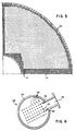
- Figure 2 is a front elevation view of the new and improved perforated flow distribution plate constructed in accordance with the present invention and illustrated as being installed within, for example, a steam generator facility such as that illustrated within Figure 1, and mounted in operative relationship with respect to the steam generator tube bundle wrapper and tube sheet;
- Figure 3 is a vertical cross-sectional view of the new and improved perforated flow distribution plate illustrated in Figure 2 and taken along the lines 3-3 of Figure 2; and
- Figure 4 shows another embodiment of the invention.
- With reference initially being made to Figure 1 of the drawings, a conventional steam generator structure or facility is disclosed. In particular, the steam generator is seen to comprise a vertically oriented, elongated entity which includes a hollow, substantially
cylindrical shell 12 having anupper shell section 14, alower shell section 16, and atransition zone section 18 integrally interconnecting together the upper andlower shell sections upper shell section 14 is greater than that of thelower shell section 16, and consequently, thetransition zone section 18 has the configuration of a conical frustum. A multitude of steam generatorheat exchanger tubes 20 extend vertically within the central portion of thelower shell section 16 of the steam generator so as to define together a tube bundle. The uppermost portion of each of thetubes 20 extends upwardly within thetransition zone section 18 of the steam generator and is seen to have an inverted U-shaped configuration. In this manner, the lower extremities of eachtube 20 can be fixedly secured within atube sheet 22 disposed within the lower end of thelower shell section 16. Integrally formed or secured to the outer periphery of the lower end of thelower shell section 16 within virtually the same horizontal plane as that of thetube sheet 22 is anannular support ring 24 by means of which the entire steam generator structure is capable of being supported upon the nuclear reactor facility or plant foundation. The lowermost end of the steam generatorlower shell section 16 is sealingly enclosed by means of a hemisphericallyshaped shell portion 26, and disposed withinhemispherical shell 26 is a vertically orienteddivider plate 28 which serves to dividehemispherical shell 26 into two spherical quadrants. As may readily be appreciated, each of the quadrants is fluidically connected to one of the extremities of each of theheat exchanger tubes 20, and each quadrant is also provided with afluid nozzle inlet nozzle 30, the left steam generatorhemispherical shell quadrant 34, the steam generator tube bundle U-shapedheat exchanger tubes 20, the right steam generator hemispherical shell quadrant 36, as viewed in Figure 1,outlet nozzle 32, and back to the nuclear reactor core. - In order to provide for the generation of steam within the steam generator, an
inlet feedwater nozzle 38 is provided within a sidewall portion of theupper shell section 14 of the steam generator, and awater conduit 40 is disposed internally ofnozzle 38. Theconduit 40 is integrally connected with anannular manifold 42 which has operatively associated in a fluidically connected manner, a multitude of upstanding, inverted J-tubes ornozzles 44 through means of which the incoming feedwater is projected downwardly in cascading sheets. In order to define a flowpath of the cascading water flowing downwardly through the steam generator, the entire tube bundle is enveloped or encased within acylindrical tube wrapper 46 which extends vertically, and substantially concentrically, within the lower andtransitional zone sections steam generator shell 12, thetube wrapper 46 being rigidly secured within theshell 12 by suitable means, not shown. In this manner, the tube wrapper 46 and the lower andtransitional zone sections shell 12 serve to define anannular downcomer region 48 through which the water flows downwardly toward the bottom of the steam generator facility. It is seen that the lower peripheral edge of thetube wrapper 46 is suspended above the upper surface of thetube sheet 22 whereby a transverse flow region is defined between thedowncomer region 48 of the generator and the tube bundle section of the generator which is disposed interiorly of thetube wrapper 46. The water therefore enters the tube bundle section of the generator, and the heat exchange process between the water and the heatedtube bundle tubes 20, through which the hot reactor core coolant is being conducted and circulated, begins to take place with the water passing between all of theheat exchange tubes 20. As a result, steam is generated; and the water and steam flow upwardly through the entire tube bundle, between thetubes 20, under natural convection. In order to provide lateral support and stabilization for theheat exchange tubes 20 throughout their vertical extent, a plurality of horizontally disposed, vertically spacedtube support plates 50 are fixedly secured to the interior wall surface of thetube wrapper 46. As is conventional, theheat exchange tubes 20 pass through holes orapertures 52 defined within thetube support plates 50, there being sufficient spatial clearance defined between thetubes 20 and the plate apertures orholes 52 so as to provide for the desired, limited lateral support and restricted movement of thetubes 20, in response to the water flow thereabout as well as thermal expansion and contraction conditions, without hindering the passage therethrough of the water and steam flowing upwardly through the generator. It is to be further noted that in view of the U-shaped configuration of thetubes 20, a tube passageway orlane 54 is defined between the legs of thetubes 20, and within each of the horizontally disposedsupport plates 50, with the exception of the lowermost plate 50', there are defined a plurality of radially alignedslots 56 through which water and steam may likewise pass from one vertically spaced or defined section of the generator heat exchanger portion to another. The lowermost support plate 50' has the configuration of an annular disc with the central portion thereof open, and in this manner, the plate 50' serves as a flow distribution baffle which effectively causes a high percentage of the incoming water to flow from the radially outer portion of the tube bundle section of the steam generator, beneath the undersurface of the plate or baffle 50', and upwardly through the large central aperture defined within the plate or baffle 50', with the remaining portion of the incoming water flow passing upwardly through the apertures orholes 52 defined within plate or baffle 50'. Water and steam can therefore flow upwardly through the various vertically spaced stages of the heat exchanger, through means of the holes orapertures 52, as well as theslots 56 and thelanes 54, in a predeterminedly defined pattern which seeks to achieve flow uniformity. In addition to thesupport plates 50,antivibration bars 58 may be provided within the uppermost portion of thewrapper 46 so as to engage the uppermost, U-shaped bent sections of theheat exchanger tubes 20 for likewise performing restrictive and stabilizing functions with respect totubes 20 in a manner similar to that ofsupport plates 50 under steam and water flow, as well as thermal expansion and contraction, conditions. As a result, excessive wear of theheat exchanger tubes 20 is effectively prevented or substantially reduced, as is vibrational noise. - The upper end of the steam generator heat
exchanger tube wrapper 46 is integrally provided with a horizontally disposed deck orcover 60 so as to seal the interior of thewrapper 46 within which the heat'exchanger U-bent tubes 20 are disposed, however, in order to permit the upward escape of the generated steam from the heat exchanger portion of the generator and out of thewrapper 46, a plurality ofholes 62 are defined within the cover ordeck 60. A plurality of upstanding swirl vaneprimary moisture separators 64 in the form of, for example, cylindrical tubes approximately 50 cm in diameter, are vertically supported atop tube wrapper deck orcover 60 with the lower ends thereof respectively in fluidic communication with the apertures orholes 62. A pair of horizontally disposed, vertically spacedlateral support plates 66 are fixedly secured with respect to the moisture separator tube systems at the upper ends and the axially central portions thereof, and in particular, it is seen that a plurality of apertures 68 are defined within the axially central orlower support plate 66 so as to permit theseparator tubes 64 to pass therethrough. A plurality of outercylindrical casings 70 concentrically surround those portions of the swirlvane separator tubes 64 which are disposed between thelateral support plates 66, and the upper ends of thecasings 70 are in contact with the undersurface of the lowerlateral support plate 66. Orificebushings 72, having a diametrical extent which is less than that of thecasings 70, are disposed withinapertures 74 defined within the upperlateral support plate 66 such that the upper ends of thebushings 72 extend slightly above the upper surface of theupper support plate 66 while the lower ends of thebushings 72 are disposed within the upper ends of thecasings 70. The upper ends of theswirl vane tubes 64 terminate at a level within thecasings 70 which is below that of upperlateral support plate 66, and in this manner, water thrown radially outwardly under centrifugal force as a result of the passage of the steam/water mixture through the swirlvane separator tubes 64, and in particular past theswirl vane separators 76 respectively disposed within eachtube 64, can collect upon the inner surface of eachcasing 70 while the steam can continue to travel axially upwardly so as to pass through the upper ends of theseparator casings 70 andorifice bushings 72. The lower ends of thecasings 70 are provided with rectangularly shaped cut-outs orapertures 78 so as to permit the aforenoted separated water to pass outwardly therethrough and over the peripheral edge of the lowerlateral support plate 66 and be discharged back into thedowncomer region 48 for recirculation back upwardly through the heater exchanger tube bundle withinwrapper 46. - Within the uppermost section of the steam
generator shell portion 14, there is defined a steam dome chamber 80 into which the steam exiting from theorifice bushings 72 enters, and within which there is disposed a plurality of stacked positiveentrainment steam dryers 82. Thedryers 82 have the configuration of cubes or rectangular parallelepipeds, and the upper surface of thedryer 82 is open so as to mate with a similarly configured cut-out oraperture 84 defined within adivider plate 86 disposed within the steam dome chamber 80. In this manner, the steam exiting from theorifice bushings 72 and passing into the steam dome chamber 80 is forced to enter the sidewalls of thedryers 82 before being further passed throughdryer 82 and upwardly out of dryer opening 84 for discharge from the steam generator through means of an axiallyupstanding steam nozzle 88 disposed atop the steam generator. Thedryers 82 serve to separate any remaining or residual water entrained within the steam before the latter is conducted to thesteam nozzle 88 for further passage to the steam turbines and electrical generators, not shown, and any such separated water is conducted vertically downwardly to a suitable pool orreservoir 89, defined within the central portion of the wrapper deck orcover 60, by means of an axially central drain pipe 90 dependently affixed to the floor 92 of thelower dryer 82. The lower end of pipe 90 is vertically spaced above wrapper deck orcover 60, and in this manner, the water collected within reservpir orpool 89 may ultimately flow radially outwardly over the wrapper deck or cover 60 so as to cascade downwardly into theannular downcomer region 48. - Having now generally described the heat exchange operation of a conventional or typical steam generator, it has been observed that when the infeed water flowing vertically downwardly within the steam generator annulus or
downcomer region 48 defined between the lowerouter shell section 16 and the heat exchangebundle tube wrapper 46 traverses the region defined beneath the lower free end of thewrapper 46 so as to commence the upward flow within thewrapper 46 and between the heatexchanger U-bent tubes 20, considerable turbulence within the flow may develop due to the generation of vortices within the fluid flow as a result of the fluid encountering the upper surface of thetubesheet 22 as well as the lower ends of the legs of theheat exchange tubes 20 affixed within thetubesheet 22 as the flow seeks to achieve the 180° reversal in flow directions as defined by means of the flow vertically downwardly within thedowncomer region 48 and vertically upwardly interiorly ofwrapper 46 and betweenheat exchanger tubes 20. Such turbulent flow conditions may result in excessive vibrational motion of theheat exchanger tubes 20 withinwrapper 46 so as to lead to rapid wear and erosion of the same. In addition, it is likewise possible that entrainment of foreign particles within the fluid flow could cause rapid degradation of thetubes 20 as a result of impaction or impingement of the same upon thetubes 20 under high velocity turbulent flow conditions. - With reference now being made to Figures 2 and 3 thereof, there is illustrated a perforated flow distribution plate arrangement generally indicated by the
reference character 100. It is to be appreciated that the perforatedflow distribution plate 100 of the present invention comprises an annulus disposed circumferentially about the entire interior portion of the steam generator although, of course, only a limited section of theplate 100 is illustrated. As particularly seen from the drawing figures, theperforated plate 100 has the form of a conical frustrum and is, in effect, a perimetrical skirt adapted to be interposed between the lowerfree edge portion 202 of the annular steam generator heat exchangertube bundle wrapper 146 and theupper surface 204 of the tubebundle tube sheet 122. It is to be noted at this juncture that the reference characters denoting, for example, the various components of the steam generator system illustrated within Figures 2 and 3 are similar to those reference characters denoting the same components of the steam generator system illustrated within Figure 1 with the exception that the reference characters employed within Figures 2 and 3 are in a 100 series of numbers. - As a result of the interdisposition of the perforated
flow distribution plate 100 between the lower free end oredge portion 202 of the steam generatortube bundle wrapper 146 and theupper surface 204 of the tubebundle tube sheet 122, thedowncomer region 148 of the steam generator, within which incoming feed water is flowing vertically downwardly as seen in the direction ofarrow 206 between the steam generatorouter shell 116 and thewrapper 146, is physically separated from theportion 208 of the steam generator which is radially internally or interiorly of thesteam generator wrapper 146 and within which the heatexchanger U-shaped tubes 20 would be disposed, although the latter are not illustrated within Figure 3. It is seen that the perforatedflow distribution plate 100 comprises a plurality of main body portions orsegments 210 within each of which there is defined a multitude of through-bores orapertures 212 which are uniformly distributed throughout each plate main body portion orsegment 210 in an array which comprises diagonally extending rows, all as best seen in Figure 2. In light of the foregoing structure, then, when the incoming infeed water flowing vertically downwardly in the direction ofarrow 206 within thedowncomer region 148 of the steam generator seeks to cross-over or traverse the region of the steam generator which is located directly beneath the lower free end orperipheral edge 202 of thetube bundle wrapper 146 so as to pass from thedowncomer region 148 of the generator into the tube bundle section orregion 208 of the generator, the water is forced to pass only through the through-bores orapertures 212 of the perforated flow distribution plate segments orsections 210. As can thus be appreciated from Figure 3, therefore, uniform flow, exhibiting substantially parallel flow paths as designated by thearrows 214, is achieved through the perforated flow distribution plate segments orsections 210, and such flow is free from turbulent conditions which characterizes the flow within such regions of a steam generator within which the perforatedflow distribution plate 100 of the present invention is not employed, such as, for example, as illustrated within Figure 1. Viewing the flow conditions in a slightly different light or from a slightly different viewpoint, the disposition of the perforatedflow distribution plate 100 within thetransition zone 216 defined between thedowncomer region 148 and thetube bundle region 208 serves to interrupt the fluidic communication between the downcomer andtube bundle regions incoming infeed water 206, which serves to induce the turbulence and the generated or developed vortices, is in fact unable to establish or generate such vortices and turbulent flow conditions because such conventional 180° flow path has been effectively severed, and in lieu thereof, there has been established a plurality of substantially parallel flow paths as schematically illustrated by thearrows 214. - In addition to aforenoted structural features per se of the perforated
flow distribution plate 100 of the present invention, and its particular disposition within thetransition zone 216 of the steam generator, it is also of importance to appreciate the fact that theplate 100 likewise serves to drastically alter the flow velocity characteristics of the incominginfeed water flow 206. More particularly, the lower free end orperipheral edge portion 202 of thesteam generator wrapper 146 is conventionally disposed above theupper surface 204 of the tube bundle tube sheet 122 a distance approximately between 30 and 35 cm, while the distance defined between thetube bundle wrapper 146 and thesteam generator shell 116 is approximately 5 or 7.5 cm. The flow velocity of theincoming infeed water 206 flowing vertically downwardly within thedowncomer region 148 is approximately 5 m per second, and therefore, in view of the fact that there is an approximate factor of five defined between the fluid flow spaces between the wrapper lower edge-tube sheet upper surface and the shell wrapper, the flow velocity of the incoming or feed water through the transition zone orregion 216 would normally be reduced by one-fifth so as to exhibit a speed of 1 m per second. In reality, however, the actual flow velocity is substantially higher, and on the order of 2.6 or 3.3 m per second due to the turbulent conditions induced within the flow path. Continuing further, by the provision of the perforatedflow distribution plate 100 of the present invention, wherein the same is provided with a porosity factor of approximately fifty per cent (50%) by means of through-bores orapertures 212, a factor of two is introduced into the system, and consequently, the flow velocity of the water through the holes orapertures 212 within the perforatedflow distribution plate 100 of the present invention is approximately 1.83 m/s (6 fps). This compares quite favorably with the aforenoted velocity characteristic of the conventional steam generator system, and in addition, it is also to be emphasized, of course, that the resulting flow through the perforatedflow distribution plate 100 of the present invention is uniform flow which is free of turbulence, vortices, and the like. Still further, in view of the uniform flow paths through theflow distribution plate 100 as schematically designated by thearrows 214, it has been experienced that the turbulent and vortex flow conditions which possibly occur within a conventional steam generator which does not employ theflow distribution plate 100 of the present invention do not in fact tend to be re-established or regenerated within thetube bundle region 208 of the generator. As a result of all of the foregoing, no substantial vibrational forces are induced upon the steam generatortube bundle tubes 20 whereby excessive wear of thetubes 20 is effectively prevented with a concomitant extension in the service life of theheat exchanger tubes 20. As an additionally desirable characteristic or feature of theflow distribution plate 100 of the present invention, each of the through-bores orapertures 212 has been predetermined so as to have a diametrical extent of approximately 6.3 'mm, and in this manner, foreign particles which may be entrained within theincoming infeed water 206, and having a diametrical size greater than 6.3 mm are prevented from entering the tube bundle section of the generator. In this manner, erosive degradation of thetubes 20 of the generator is minimized as a result of eliminating such particles from thetube bundle region 208 of the generator wherein such particles would normally impact and impinge upon thetubes 20. - With reference still being made to Figure 3 of the drawings, it is seen that in order to provide for the installation of the perforated
flow distribution plate 100 of the present invention in connection with, for example, already existing steam generator facilities, the upper edge of eachperforated plate segment 210 is integrally provided with anupstanding flange portion 218 as well as a horizontally extendingflange portion 220 such that the two flanged portions together define an L-shaped shoulder or seat for engagement with the lower free end orperipheral edge portion 202 of thegenerator wrapper 146. The primary ormain body portion 210 of each perforated plate segment is seen to be inclined with respect to the horizontal through means of an angle a of approximately 80°, and consequently, when theplate segments 210 are wedgingly interposed between theupper surface 204 of thetube sheet 122 and the lower freeperipheral edge portion 202 of thegenerator wrapper 146 such that thewrapper edge portion 202 is seated within the plate shoulder region as defined by means of the plate segment flangedportions inclined plate segments 210 will be disposed within a stable erected mode relative to thegenerator wrapper 146 and thetube sheet 122, under the influence of theincoming infeed water 206, it being remembered that theperforated flow plate 100 of the present invention extends circumferentially about the entirelower end portion 202 of the wrapper. - In order to actually install the perforated
flow distribution plate 100 of the present invention into existing steam generator facilities, an access must initially be made within the steam generator outer shell 11j6 so as to permit insertion of theindividual plate segments 210 into theannular downcomer region 148 of the generator as well as to provide manipulative access to thesegments 210 once the same are disposed within thedowncomer region 148. If the generator vessel orshell 116 is conventionally provided with manipulative access passageways, such as, for example, that shown at 222 in Figure 1, then such passageways may be employed for facilitating additional manipulation of theplate segments 210 within thedowncomer region 148, provided that such access passageways are located at a suitable or proper elevational level with respect to thetube sheet such access passageways 222 are not conventionally large enough to permit the insertion of theplate segments 210 into thedowncomer region 148. Once individual perforated flowdistribution plate segments 210 are inserted through the access holes in thegenerator shell 116, adjacent segments may be securely fastened together either by means of welding techniques or besuitable brackets 224 provided upon the upper side edge of each plate segment, within or through whichbolt fasteners 226 may be inserted. Whilesuch brackets 224 are illustrated as being employed only along the upper extent of each plate segment, it is understood that if such be desired, similar brackets and bolt fasteners may likewise be employed along the lower extent or edge of each of thesegments 210 so as to maintain the abutting side edges of thesegments 210 in close, sealed contact with each other. Upon completion of the welding or bolt fastening processing of, for example, the first twosegments 210, the assembledplate segments 210 may be translated circumferentially within thetransition zone 216 of the generator in order to accommodate thenext plate segment 210 to be welded or bolt fastened to the precedingplate segments 210. It is to be understood that in view of the fact that the circumferential curvature of each of theplate segments 210 is similar to that of thegenerator wrapper 146, and in particular, the fact that the circumferential curvature of the plateflanged portions transition zone 216 of the generatorfor accomplishing the installation of theentire plate 100 within the generator should not present any problems. Upon assembly together of all of theplate segments 210, and the disposition of theentire plate 100 about the lower periphery of thegenerator wrapper 146, the first and last twoplate segments 210 may be welded or bolted together, however, it is noted that thesegments 210 are not, and need not, be fixedly secured to thegenerator wrapper 146 within existing steam generator facilities. Such assembly processing or techniques not only permits the circumferential translation of the assembled segments about thetransition zone 216 of the generator so as to accommodate additional segments for assembly thereof, but in addition, such foreshortens the requisite assembly time and any exposure of such assembly or maintenance personnel to radiation as a result of the core coolant having been conducted through the heat exchangertube bundle tubes 20. Upon completion of the entire assembly operation, it is simply necessary to close the access hole originally made within thegenerator shell 116 so as to preserve the structural integrity of the shell and the generator. - In accordance with an alternative mode of installing the perforated
flow distribution plate 100 of the present invention within the steam generator facility, access to the interior of the steam generator shell may be accomplished through means of maintenance or inspection manways conventionally provided wtihin the steam dome chamber region 80 of the upper steamgenerator shell section 14 as shown in Figure 1 at 228. The individual circumferentially curved orarcuate plate segements 210 may then be lowered vertically downwardly within the upper andtransition zone sections downcomer region 148. The lower maintenance of personnel access orinspection manways 222 may then be utilized for performance of the actual installation, circumferential translation, and in-situ welding or bolt fastening operations in connection with theplate 100, if themanways 222 are suitably located elevationally with respect to thetube sheet 122. If themanways 222 are not suitably located, then access penetrations are again required to be made within thesteam generator shell 116, however, these penetrations need not be as large as those required in accordance with the previous mode of installation for they do not have to provide for the insertion or introduction of theplate segments 210 into the generator, is foreseeable that some difficulty might possibly be encountered in accordance with this mode of installation of theplate segments 210 into the generator in that the tapered transition zone annulus, as defined between the shelltransition zone section 18 and the corresponding portion of the tube bundle wrapper, may not readily permit traversal therethrough of the circumferentially curved or arcuate-shapedplate segments 210, in which instance access penetrations, not shown, in the form of vertically extending grooves or the like, may have to be provided within the outer surface of the tube bundle wrapper. Lowering of theplate segments 210 frommanways 228 to thetube sheet - In the instance of new steam generator facilities, the perforated
flow distribution plate 100 of the present invention may simply be provided as an integral skirt portion of what otherwise would be the conventional tube bundle wrapper, and consequently, the foregoing installation requirements would not longer be required. It is noted that thetube bundle wrapper 146 is conventionally fabricated from a suitable carbon steel, however, in order to improve the erosive and corrosive resistivity of the perforated or foraminousflow distribution plate 100 of the present invention, it might be best to fabricate the same from a suitable metal, such as, for example, INCONEL 600, a nickel-chromium alloy. This is particularly desirable in view of the fact that theplate 100 also serves to prevent the introduction of foreign particles, larger than the aforenoted predetermined size of 6.3 mm in diameter, into thetube bundle region 208 of the generator. Long term testing in reference water chemistry has shown that plates having such through-holes defined therein do not experience any substantial tendency for erosion, sludge deposition, or the like, and the fabrication of theplate segments 210 from INCONEL 600 would enhance these operative and service life characteristics or properties still further. In the instance that theplate segments 210 are therefore fabricated from a different material than that of thewrapper 146, theplate segments 210 may be welded to thewrapper 146 prior to the installation of thewrapper 146 within the generator, or still alternatively, a one- piece perforated flow distribution plate skirt, fabricated of INCONEL 600 may be welded or otherwise secured to the lower end of thewrapper 146 prior to installation of the same within the generator. It is of course to be understood that in connection with existing facilities, theplate segments 210 fabricated of INCONEL 600 would be installed in accordance with the aforenoted in-situ techniques, and not directly affixed or secured to thewrapper 146. The width of theindividual plate segments 210 will be dictated by means of commercially available strip dimensions, and the thickness of theplate segments 210 may be specified by means of suitable stress analyses, anticipated transient flow loads under, for example, fluid line rupture conditions, and the like. - In the embodiment shown in Figure 4 a plurality of strong
cylindrical members 124 constructed as either solid rods or thick-walled, hollow tubes, for example, having a wall thickness of greater than about 2.5 mm are provided. - The
cylindrical members 124 generally have a length sufficient to span theopening 125 and are arranged around the lower peripheral portion of thetube bundle 108 in alignment with the longitudinal axis thereof. Thecylindrical members 124 are dimensioned to have an outside diameter corresponding to the outside diameter of theheat transfer tubes 20 and are arranged in an array having a pitch corresponding to the pitch of the heat transfer tubes. In this regard, thecylindrical members 124, by having the same outside diameter and pitch as that of theheat transfer tubes 20, act like another row ofheat transfer tubes 20 to the flowing fluid such that the pressure loss of the fluid flowing through theannular downcomer passage 106 and across the cylindrical members into thetube bundle 108 is almost negligible. Accordingly, the cylindrical members function as an almost indestructible screen against impacting pieces of metallic debris swept along by the fluid flowing within theannular downcomer passage 106. - The
cylindrical members 124 can be secured at their lower ends to thetube sheet 122 withinopenings 126 provided about the periphery of the tube bundle. Theopenings 126 may be threaded so as to receive a corresponding threaded portion of the lower ends of thecylindrical members 124, or may provide for a slip or friction fit therebetween. In any event, thecylindrical members 124 can be spot-welded or permanently fastened in some other way to thetube sheet 122 if desired. The upper ends of thecylindrical members 124, extend throughopenings 128 provided within the first flowdistribution support baffle 112 and are secured to thesupport baffle 112 by means of a ·collar 130 engaging 'a portion of the cylindrical members, as well as by welding them together. Thecylindrical members 124 extend between thetube sheet 122 and thesupport baffle 112. However, it is not necessary that thecylindrical members 124 extend to thefirst support baffle 112. It is only require that thecylindrical members 124 extend generally across the extent of theopening 125, whereby the upper end of the cylindrical members may terminate freely under the first support baffle at a location indicated, for example, by the dottedlines 132. Protection above thesupport baffle 112 is not required, as this flow distribution plate support baffle prevents any debris from passing therebeyond.
Claims (8)
Applications Claiming Priority (4)
| Application Number | Priority Date | Filing Date | Title |
|---|---|---|---|
| US67182284A | 1984-11-15 | 1984-11-15 | |
| US67182184A | 1984-11-15 | 1984-11-15 | |
| US671821 | 1984-11-15 | ||
| US671822 | 1984-11-15 |
Publications (2)
| Publication Number | Publication Date |
|---|---|
| EP0183049A1 EP0183049A1 (en) | 1986-06-04 |
| EP0183049B1 true EP0183049B1 (en) | 1989-10-18 |
Family
ID=27100623
Family Applications (1)
| Application Number | Title | Priority Date | Filing Date |
|---|---|---|---|
| EP85113455A Expired EP0183049B1 (en) | 1984-11-15 | 1985-10-23 | Perforated flow distribution plate |
Country Status (5)
| Country | Link |
|---|---|
| EP (1) | EP0183049B1 (en) |
| KR (1) | KR860004271A (en) |
| CN (1) | CN1005283B (en) |
| DE (1) | DE3573827D1 (en) |
| ES (1) | ES8708047A1 (en) |
Families Citing this family (14)
| Publication number | Priority date | Publication date | Assignee | Title |
|---|---|---|---|---|
| FR2684433B1 (en) * | 1991-12-02 | 1994-01-07 | Framatome Sa | DEVICE FOR TRAPPING MIGRANT BODIES WITHIN THE SECONDARY CIRCUIT OF A STEAM GENERATOR. |
| EP0557173A1 (en) * | 1992-02-17 | 1993-08-25 | Framatome | Steam generator with inlet of feed water in the lower part |
| FR2690504B1 (en) * | 1992-04-28 | 1994-06-03 | Framatome Sa | STEAM GENERATOR WITH DEVICE FOR DISTRIBUTING AND REPAIRING FOOD WATER AND RECIRCULATING WATER IN THE SECONDARY PART. |
| FR2705759B1 (en) * | 1993-05-27 | 1995-07-07 | Framatome Sa | Steam generator equipped with a device for trapping migrant bodies. |
| KR100572118B1 (en) * | 2005-01-28 | 2006-04-18 | 주식회사 에이디피엔지니어링 | Plasma processing apparatus |
| JP2006322683A (en) * | 2005-05-20 | 2006-11-30 | Mitsubishi Heavy Ind Ltd | Steam generator |
| US8215379B2 (en) * | 2009-04-29 | 2012-07-10 | Babcock & Wilcox Canada Ltd. | Feedwater debris trap |
| CN103377735B (en) * | 2012-04-27 | 2016-08-03 | 上海核工程研究设计院 | A kind of reactor bottom in-pile component |
| CN102777161A (en) * | 2012-06-18 | 2012-11-14 | 陕西得波材料科技有限公司 | Wing-shaped mixed-phase steam intake column uniform-dryness distributor |
| US9175845B2 (en) * | 2012-07-10 | 2015-11-03 | Westinghouse Electric Company Llc | Axial flow steam generator feedwater dispersion apparatus |
| CN105042555B (en) * | 2015-09-02 | 2017-03-29 | 中国工程物理研究院材料研究所 | A kind of implementation method of flow type steam generator |
| CN107167010B (en) * | 2017-04-28 | 2019-03-08 | 山东大学 | A kind of loop circuit heat pipe |
| CN107167009B (en) * | 2017-04-28 | 2019-03-08 | 山东大学 | The annular and separation device loop circuit heat pipe of hydraulic diameter variation |
| NL2021445B1 (en) * | 2018-08-09 | 2020-02-20 | Awect Bv | High pressure heating installation comprising an advanced panel design and cladding thereof |
Family Cites Families (7)
| Publication number | Priority date | Publication date | Assignee | Title |
|---|---|---|---|---|
| US3076444A (en) * | 1962-01-31 | 1963-02-05 | Foster Wheeler Corp | Vapor generators |
| US3811498A (en) * | 1972-04-27 | 1974-05-21 | Babcock & Wilcox Co | Industrial technique |
| US3923007A (en) * | 1972-12-19 | 1975-12-02 | Siemens Ag | Emergency water-cooling system for a steam generator for a pressurized-water coolant nuclear reactor |
| US3916844A (en) * | 1974-07-29 | 1975-11-04 | Combustion Eng | Steam generator blowdown apparatus |
| DE2720812C2 (en) * | 1977-05-09 | 1978-11-16 | Kraftwerk Union Ag, 4330 Muelheim | Vertical feed water preheater with steam trap |
| FR2458781A1 (en) * | 1979-06-13 | 1981-01-02 | Stein Industrie | Heat exchanger with inverted J tubes - has annular and central tube plates constituting prim. fluid inlet and outlet plates near opposite ends facilitating heat transfer |
| FR2477265A1 (en) * | 1980-02-29 | 1981-09-04 | Framatome Sa | PRE-HEATING STEAM GENERATOR |
-
1985
- 1985-10-23 DE DE8585113455T patent/DE3573827D1/en not_active Expired
- 1985-10-23 EP EP85113455A patent/EP0183049B1/en not_active Expired
- 1985-11-11 ES ES548750A patent/ES8708047A1/en not_active Expired
- 1985-11-15 CN CN85108386.2A patent/CN1005283B/en not_active Expired
- 1985-11-15 KR KR1019850008557A patent/KR860004271A/en not_active Application Discontinuation
Also Published As
| Publication number | Publication date |
|---|---|
| CN1005283B (en) | 1989-09-27 |
| CN85108386A (en) | 1986-09-03 |
| EP0183049A1 (en) | 1986-06-04 |
| KR860004271A (en) | 1986-06-20 |
| ES8708047A1 (en) | 1987-09-01 |
| DE3573827D1 (en) | 1989-11-23 |
| ES548750A0 (en) | 1987-09-01 |
Similar Documents
| Publication | Publication Date | Title |
|---|---|---|
| EP0183049B1 (en) | Perforated flow distribution plate | |
| US4629481A (en) | Low pressure drop modular centrifugal moisture separator | |
| US5037605A (en) | Nuclear fuel assembly debris filter | |
| US5094802A (en) | Nuclear fuel assembly debris filter | |
| EP0015510B1 (en) | Device to reduce local heat flux through a heat exchanger tube | |
| US8002866B2 (en) | Steam-water separator | |
| US4736713A (en) | Foraminous or perforated flow distribution plate | |
| US6498827B1 (en) | Heat exchanger tube support structure | |
| US4573526A (en) | Steam generator flow control device | |
| EP0055413B1 (en) | Orificing of steam separators for uniform flow distribution in riser area of steam generators | |
| KR20170117144A (en) | Steam generator with inclined tubesheet | |
| EP2694904B1 (en) | Steam generator tube lane flow buffer | |
| KR100304602B1 (en) | Coolant discharge fuel rod for light water reactor | |
| US4788032A (en) | Nuclear reactor with flow guidance in the upper internals | |
| US3267906A (en) | Compact heat source and heat exchanger | |
| US3895674A (en) | Inlet flow distributor for a heat exchanger | |
| US20040146134A1 (en) | Heat exchanger tube support structure | |
| KR100308868B1 (en) | Heat exchanger with secondary water supply in the upper zone by drainage | |
| US4462340A (en) | Arrangement for preventing the formation of cracks on the inside surfaces of feedwater line nozzles opening into pressure vessels | |
| CA2702332C (en) | Feedwater debris trap | |
| US4644908A (en) | Steam generator wrapper closure and method of installing the same | |
| WO2021102885A1 (en) | Vertical type steam generator of pressurized water reactor nuclear power plant and loosening part capturing device therefor | |
| CA1085244A (en) | Vapor generating unit blowdown arrangement | |
| US5329886A (en) | Steam generator | |
| JPS61122402A (en) | Steam generator |
Legal Events
| Date | Code | Title | Description |
|---|---|---|---|
| PUAI | Public reference made under article 153(3) epc to a published international application that has entered the european phase |
Free format text: ORIGINAL CODE: 0009012 |
|
| AK | Designated contracting states |
Kind code of ref document: A1 Designated state(s): BE DE FR GB IT SE |
|
| 17P | Request for examination filed |
Effective date: 19861111 |
|
| 17Q | First examination report despatched |
Effective date: 19871207 |
|
| ITF | It: translation for a ep patent filed |
Owner name: ING. ZINI MARANESI & C. S.R.L. |
|
| GRAA | (expected) grant |
Free format text: ORIGINAL CODE: 0009210 |
|
| AK | Designated contracting states |
Kind code of ref document: B1 Designated state(s): BE DE FR GB IT SE |
|
| ET | Fr: translation filed | ||
| REF | Corresponds to: |
Ref document number: 3573827 Country of ref document: DE Date of ref document: 19891123 |
|
| PLBE | No opposition filed within time limit |
Free format text: ORIGINAL CODE: 0009261 |
|
| STAA | Information on the status of an ep patent application or granted ep patent |
Free format text: STATUS: NO OPPOSITION FILED WITHIN TIME LIMIT |
|
| 26N | No opposition filed | ||
| PGFP | Annual fee paid to national office [announced via postgrant information from national office to epo] |
Ref country code: SE Payment date: 19900926 Year of fee payment: 6 |
|
| PGFP | Annual fee paid to national office [announced via postgrant information from national office to epo] |
Ref country code: BE Payment date: 19901010 Year of fee payment: 6 |
|
| ITTA | It: last paid annual fee | ||
| PGFP | Annual fee paid to national office [announced via postgrant information from national office to epo] |
Ref country code: DE Payment date: 19901228 Year of fee payment: 6 |
|
| PGFP | Annual fee paid to national office [announced via postgrant information from national office to epo] |
Ref country code: FR Payment date: 19910917 Year of fee payment: 7 |
|
| PG25 | Lapsed in a contracting state [announced via postgrant information from national office to epo] |
Ref country code: SE Effective date: 19911024 |
|
| PG25 | Lapsed in a contracting state [announced via postgrant information from national office to epo] |
Ref country code: BE Effective date: 19911031 |
|
| BERE | Be: lapsed |
Owner name: WESTINGHOUSE ELECTRIC CORP. Effective date: 19911031 |
|
| PG25 | Lapsed in a contracting state [announced via postgrant information from national office to epo] |
Ref country code: DE Effective date: 19920701 |
|
| PG25 | Lapsed in a contracting state [announced via postgrant information from national office to epo] |
Ref country code: FR Effective date: 19930630 |
|
| REG | Reference to a national code |
Ref country code: FR Ref legal event code: ST |
|
| PGFP | Annual fee paid to national office [announced via postgrant information from national office to epo] |
Ref country code: GB Payment date: 19941019 Year of fee payment: 10 |
|
| EUG | Se: european patent has lapsed |
Ref document number: 85113455.1 Effective date: 19920510 |
|
| PG25 | Lapsed in a contracting state [announced via postgrant information from national office to epo] |
Ref country code: GB Effective date: 19951023 |
|
| GBPC | Gb: european patent ceased through non-payment of renewal fee |
Effective date: 19951023 |