EP0183023B1 - Gas laser with transversal coupling of high-frequency energy - Google Patents
Gas laser with transversal coupling of high-frequency energy Download PDFInfo
- Publication number
- EP0183023B1 EP0183023B1 EP85112879A EP85112879A EP0183023B1 EP 0183023 B1 EP0183023 B1 EP 0183023B1 EP 85112879 A EP85112879 A EP 85112879A EP 85112879 A EP85112879 A EP 85112879A EP 0183023 B1 EP0183023 B1 EP 0183023B1
- Authority
- EP
- European Patent Office
- Prior art keywords
- tubular body
- laser
- partial
- gas
- sections
- Prior art date
- Legal status (The legal status is an assumption and is not a legal conclusion. Google has not performed a legal analysis and makes no representation as to the accuracy of the status listed.)
- Expired - Lifetime
Links
- 230000008878 coupling Effects 0.000 title claims description 3
- 238000010168 coupling process Methods 0.000 title claims description 3
- 238000005859 coupling reaction Methods 0.000 title claims description 3
- 238000001816 cooling Methods 0.000 claims description 11
- 230000000694 effects Effects 0.000 description 3
- 238000006880 cross-coupling reaction Methods 0.000 description 2
- 238000013461 design Methods 0.000 description 1
- 238000011161 development Methods 0.000 description 1
- 230000002349 favourable effect Effects 0.000 description 1
- 230000017525 heat dissipation Effects 0.000 description 1
- 238000010438 heat treatment Methods 0.000 description 1
- 238000000960 laser cooling Methods 0.000 description 1
- 239000002184 metal Substances 0.000 description 1
- 238000000034 method Methods 0.000 description 1
- 238000012545 processing Methods 0.000 description 1
- 238000012549 training Methods 0.000 description 1
- 230000007704 transition Effects 0.000 description 1
Images
Classifications
-
- H—ELECTRICITY
- H01—ELECTRIC ELEMENTS
- H01S—DEVICES USING THE PROCESS OF LIGHT AMPLIFICATION BY STIMULATED EMISSION OF RADIATION [LASER] TO AMPLIFY OR GENERATE LIGHT; DEVICES USING STIMULATED EMISSION OF ELECTROMAGNETIC RADIATION IN WAVE RANGES OTHER THAN OPTICAL
- H01S3/00—Lasers, i.e. devices using stimulated emission of electromagnetic radiation in the infrared, visible or ultraviolet wave range
- H01S3/02—Constructional details
- H01S3/03—Constructional details of gas laser discharge tubes
- H01S3/038—Electrodes, e.g. special shape, configuration or composition
-
- H—ELECTRICITY
- H01—ELECTRIC ELEMENTS
- H01S—DEVICES USING THE PROCESS OF LIGHT AMPLIFICATION BY STIMULATED EMISSION OF RADIATION [LASER] TO AMPLIFY OR GENERATE LIGHT; DEVICES USING STIMULATED EMISSION OF ELECTROMAGNETIC RADIATION IN WAVE RANGES OTHER THAN OPTICAL
- H01S3/00—Lasers, i.e. devices using stimulated emission of electromagnetic radiation in the infrared, visible or ultraviolet wave range
- H01S3/02—Constructional details
- H01S3/03—Constructional details of gas laser discharge tubes
- H01S3/036—Means for obtaining or maintaining the desired gas pressure within the tube, e.g. by gettering, replenishing; Means for circulating the gas, e.g. for equalising the pressure within the tube
-
- H—ELECTRICITY
- H01—ELECTRIC ELEMENTS
- H01S—DEVICES USING THE PROCESS OF LIGHT AMPLIFICATION BY STIMULATED EMISSION OF RADIATION [LASER] TO AMPLIFY OR GENERATE LIGHT; DEVICES USING STIMULATED EMISSION OF ELECTROMAGNETIC RADIATION IN WAVE RANGES OTHER THAN OPTICAL
- H01S3/00—Lasers, i.e. devices using stimulated emission of electromagnetic radiation in the infrared, visible or ultraviolet wave range
- H01S3/02—Constructional details
- H01S3/04—Arrangements for thermal management
- H01S3/041—Arrangements for thermal management for gas lasers
-
- H—ELECTRICITY
- H01—ELECTRIC ELEMENTS
- H01S—DEVICES USING THE PROCESS OF LIGHT AMPLIFICATION BY STIMULATED EMISSION OF RADIATION [LASER] TO AMPLIFY OR GENERATE LIGHT; DEVICES USING STIMULATED EMISSION OF ELECTROMAGNETIC RADIATION IN WAVE RANGES OTHER THAN OPTICAL
- H01S3/00—Lasers, i.e. devices using stimulated emission of electromagnetic radiation in the infrared, visible or ultraviolet wave range
- H01S3/05—Construction or shape of optical resonators; Accommodation of active medium therein; Shape of active medium
- H01S3/06—Construction or shape of active medium
- H01S3/07—Construction or shape of active medium consisting of a plurality of parts, e.g. segments
- H01S3/073—Gas lasers comprising separate discharge sections in one cavity, e.g. hybrid lasers
- H01S3/076—Folded-path lasers
-
- H—ELECTRICITY
- H01—ELECTRIC ELEMENTS
- H01S—DEVICES USING THE PROCESS OF LIGHT AMPLIFICATION BY STIMULATED EMISSION OF RADIATION [LASER] TO AMPLIFY OR GENERATE LIGHT; DEVICES USING STIMULATED EMISSION OF ELECTROMAGNETIC RADIATION IN WAVE RANGES OTHER THAN OPTICAL
- H01S3/00—Lasers, i.e. devices using stimulated emission of electromagnetic radiation in the infrared, visible or ultraviolet wave range
- H01S3/09—Processes or apparatus for excitation, e.g. pumping
- H01S3/097—Processes or apparatus for excitation, e.g. pumping by gas discharge of a gas laser
- H01S3/0975—Processes or apparatus for excitation, e.g. pumping by gas discharge of a gas laser using inductive or capacitive excitation
Definitions
- the invention relates to a gas laser with a tubular body for receiving a laser gas flowing along the laser beam, wherein along the tubular body opposite one another, electrodes for the cross coupling of high-frequency energy are according to the preamble of claim 1, as he is known from EP-A-0152084.
- a gas laser with a tubular body for receiving a laser gas flowing along the laser beam, wherein along the tubular body opposite one another, electrodes for the cross coupling of high-frequency energy are according to the preamble of claim 1, as he is known from EP-A-0152084.
- the object of the invention is to develop a gas laser of the type mentioned at the outset in such a way that it can be used for high powers and manages with the lowest possible power losses.
- partial electrodes or partial electrode pairs with in particular the same length are used for the transverse coupling of high-frequency energy Partial electrodes, which are mounted in succession in the longitudinal direction of the tubular body at a distance.
- the mutual spacing of the partial electrodes depends on the space requirement of the inlets and outlets for the laser gas and should be as small as possible at least in the case of a straight, elongated, tubular body.
- the partial flows of the laser gas can theoretically be cooled individually, but this leads to a relatively large outlay on equipment and space. Therefore, the more advantageous solution is to combine the partial gas flows, at the latest at the inlet of a common cooling device. The same applies analogously to the cooled partial streams to be returned.
- each end of the tubular body has a gas inlet assigned.
- the inflowing gas is cooler than the outflowing and therefore introducing the cool partial air flows in the region of the two ends of the tubular body keeps the tube ends cool.
- the laser mirrors in a known manner, namely the end mirror and a partially transparent so-called decoupling mirror.
- the bearings of the mirrors are sensitive to heat and therefore cooling of the tubular body by the cool partial air flows in these areas is very advantageous.
- the tubular body has a U-shaped shape.
- “folded” lasers are already known in various types. In addition to the two end mirrors mentioned, they have additional deflecting mirrors. In the case of the U-shape, two deflecting mirrors inclined at 45 ° to the longitudinal axis of the U-legs are required. You are at the transition from the U-legs to the U-cross piece.
- a further development of the invention is that both in the area of the free as well as the U-leg ends assigned to the U-cross piece, there is an inlet and in the middle area of the U-leg, there is an outlet.
- four inlets and two outlets are sufficient in this embodiment, which are designed as double outlets to a certain extent.
- the inlets of the free U-leg ends and the inlets of the U-leg ends assigned to the U-crosspiece as well as the two outlets or double outlets are combined in terms of flow or connected to one another, for example via short duct sections.
- the number of supply and discharge lines to and from the cooling device is reduced to one supply line and two return lines or a bifurcated return line.
- the number of these lines naturally increases when the division into six, eight and more flow sections is carried out. But they also apply to such Embodiments summarized the inlets and outlets according to the embodiment of the invention described above. Otherwise, the joint feed of the cooled gas stream for the sections assigned to the U-crosspiece could also take place in the U-crosspiece itself.
- Another variant of the invention is characterized in that all sub-electrodes are connected to a common high-frequency generator. Like the partial air flows, the circuits for the partial electrodes are therefore combined in such a way that, despite the division of the electrodes into partial electrodes, only one generator is still required. Furthermore, it is particularly advantageous that the partial flows of the laser gas the tubular body at high speed, of at least 50 m / sec. flow through, i.e. it is a fast-flowing laser. As already explained at the beginning, it is necessary to keep the heating of the gas in the tubular body to a minimum and to remove the heat absorbed as quickly as possible. The partial flows result in a short dwell time in the tubular body at a certain flow rate and this becomes a minimum if the flow rate is chosen to be particularly high.
- Another object of the present invention is to provide a gas laser which has an energy distribution in the gas jet which is as uniform as possible. This is achieved in that the electrode pairs or sections thereof are arranged offset from one another in the circumferential direction of the tubular body, as is stated in the characterizing part of claim 1.
- At least one pair of electrodes or a section thereof is rotatably arranged with respect to the gas stream or laser beam.
- a particularly simple type of rotary arrangement is obtained if the electrode pairs or their sections are firmly connected to the gas pipe and divided into several sections, at least one of which is rotatably mounted. It is expedient to connect the rotatable electrodes or the tube sections with an adjusting device so that the adjustment can be carried out by a control unit or by a program control.
- a locking device is also provided.
- JP-A-603170 describes an HF-excited gas laser with electrode pairs which are wound spirally around the tube or are offset in the circumferential direction of the tube.
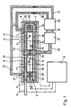
- the gas laser has a tubular body 1, preferably with a circular inner and outer cross section, in which both the laser gas 2, preferably CO 2 gas, and the laser beam are located.
- the mirror units 3 and 4 are attached to the two ends. The latter is equipped with the end mirror, while a partially transparent so-called decoupling mirror is located on the mirror unit 3.
- the generated laser beam exits via this and it arrives at a processing point or the like via a laser feed 5.
- the tubular body 1 is preferably formed into a U, as a result of which its length is reduced to approximately half. However, this requires the attachment of two deflecting mirrors 6 and 7 for the laser beam.
- the energy required to generate the laser beam is the tubular body supplied via two opposing electrodes, which is why it is a gas laser with cross coupling.
- the laser is operated with high-frequency energy, which comes from a high-frequency generator 8.
- the two electrodes which, as said, extend in the longitudinal direction of the tubular body and each encompass a partial circumference, are in partial electrodes 9, 10; 11, 12; 13, 14; 15, 16 divided.
- the sub-electrodes 9 and 10 or 11 and 12 or 13 and 14 or 15 and 16 each have the same length, the same size and the same shape and form a pair of sub-electrodes. All partial electrodes or pairs of partial electrodes are connected to a single common high-frequency generator 8 via lines shown in dash-dot lines.
- the tubular body has several gas inlets and outlets. Each sub-stream has an inlet and an outlet, but these can be summarized at least in part.
- both in the area of the mirror units 3 and 4 and the deflection mirror 6 and 7 each have an inlet 21, 22, 23, 24.
- the inlets 21 and 22 on the one hand and the inlets 23 and 24 on the other hand are preferably connected to one another in terms of flow via a channel 25 or 26 or the like.
- a feed line 27 or 28 leads to each, which is connected to one or two separate outlets of a blower 29, which draws in the cooled gas from a laser gas cooling device 31, if necessary, via a line 30.
- the heated laser gas flows to this cooling device, preferably via a common supply line 32.
- a common outlet 33 is provided for the partial flows 19 and 20.
- a discharge device 35 the two “double outlets” 33 and 34 are connected to one another via a symbolically drawn channel 36, which in turn is in flow connection with the common supply line 32. Conveniently, this ends, contrary to the schematic illustration, at the point marked by a circle 37. The same applies analogously to the channels 25 and 26.
- Corresponding to the discharge device 35 preferably identical feed devices 38 and 39 in the area of the channels 25 and 26.
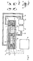
- the electrode pairs 40 to 43 are arranged offset from one another in the circumferential direction of the tubular body 1 in order to obtain a distribution of the energy in the gas stream that is as uniform as possible, as can be seen in FIG. 3.
- the tube sections on which the electrode pairs are located are rotatably mounted with respect to the other tube parts, the electrode pairs being firmly attached to the associated tube sections.
- Fig. 4 shows that a gear 44 is attached to a pipe section, in which a pinion 45 engages. This is connected to an adjusting device, not shown, which in turn can be connected to a program control or the like.
Landscapes
- Physics & Mathematics (AREA)
- Electromagnetism (AREA)
- Engineering & Computer Science (AREA)
- Plasma & Fusion (AREA)
- Optics & Photonics (AREA)
- Lasers (AREA)
Description
Die Erfindung bezieht sich auf einen Gas-Laser mit einem rohrartigen Körper zur Aufnahme eines entlang dem Laserstrahl strömenden Laser-Gases, wobei sich längs des rohrartigen Körpers einander gegenüberliegend, Elektroden für die Quereinkopplung von Hochfrequenz-Energie befinden gemäß dem Oberbegriff des Anspruchs 1, wie er aus EP-A-0152084 bekannt ist. Beim Betrieb eines derartigen Lasers entsteht Wärme, die möglichst vollständig und rasch abgeführt werden muß. Bei Lasern geringerer Leistung ist das Problem der Wärmeabfuhr naturgemäß geringer als bei einem Laser hoher Leistung, wie er beispielsweise in der Industrie zum Schneiden von Blechen u.dgl. eingesetzt wird. Wird die Wärme nur ungenügend ab geführt, so hat dies eine nicht unerhebliche Leistungsminderung zur Folge.The invention relates to a gas laser with a tubular body for receiving a laser gas flowing along the laser beam, wherein along the tubular body opposite one another, electrodes for the cross coupling of high-frequency energy are according to the preamble of claim 1, as he is known from EP-A-0152084. When operating such a laser, heat is generated which must be dissipated as completely and quickly as possible. With lower power lasers, the problem of heat dissipation is naturally less than with a high power laser, such as that used in the industry for cutting sheet metal and the like. is used. If the heat is insufficient led, this results in a not inconsiderable reduction in performance.
Es ist bei Gas-Lasern bereits bekannt, die Laserkühlung durch Kühlung des Laser-Gases zu bewirken. Dies bedeutet, daß das Laser-Gas in einem Kühlkreislauf strömt, der teilweise durch den rohrartigen Körper gebildet wird und in dem sich eine entsprechende Kühlvorrichtung befindet.In gas lasers, it is already known to effect laser cooling by cooling the laser gas. This means that the laser gas flows in a cooling circuit which is partially formed by the tubular body and in which a corresponding cooling device is located.
Die Aufgabe der Erfindung besteht nun darin, einen Gas-Laser der eingangs genannten Art so weiterzubilden, daß er für hohe Leistungen brauchbar ist und mit möglichst geringen Leistungsverlusten auskommt.The object of the invention is to develop a gas laser of the type mentioned at the outset in such a way that it can be used for high powers and manages with the lowest possible power losses.
Zur Lösung dieser Aufgabe dienen im Anspruch 1 angegbene Merkmale. Bei diesem Gas-Laser wird also das Laser-Gas in der von Lasern anderer Art bekannten Weise mit Hilfe einer Kühlvorrichtung gekühlt, jedoch ist die Gasführung in besonderer Weise ausgebildet. Der Gasstrom im rohrartigen Körper wird gewissermaßen in Teilströme unterteilt, die einzeln aus dem rohrartigen Körper herausgeleitet und wieder eingespeist werden und die aneinandergereiht den gesamten rohrartigen Körper ausfüllen. Weil nunmehr das Gas nur noch eine Teillänge des rohrartigen Körpers durchströmt, kann es sich aufgrund seiner geringeren Verweildauer einerseits nicht so stark erwärmen und andererseits wird dadurch nicht nur an einer Stelle, sondern an mehreren Stellen jeweils gekühltes Laser-Gas eingespeist. Dies hält insgesamt die Temperatur im rohrartigen Körper nieder und bewirkt die angestrebte Leistungssteigerung. Um die Ein- und Auslässe für das Laser-Gas günstig plazieren sowie strömungstechnisch vorteilhaft ausbilden zu können, verwendet man an Stelle zweier sich über die gesamte Länge des rohrartigen Körpers erstreckender Elektroden für die Quereinkopplung von Hochfrequenz-Energie Teilelektroden bzw. Teilelektrodenpaare mit insbesondere gleich langen Teilelektroden, die in Längsrichtung des rohrartigen Körpers mit Abstand aufeinanderfolgend montiert sind. Der gegenseitige Abstand der Teilelektroden richtet sich nach dem Platzbedarf der Ein- und Auslässe für das Laser-Gas und soll zumindet bei einem geraden, langgestreckten, rohrartigen Körper so gering wie möglich sein.Features specified in claim 1 serve to solve this problem. In the case of this gas laser, the laser gas is thus cooled in the manner known from lasers of other types with the aid of a cooling device, but the gas flow is designed in a special way. The gas flow in the tubular body is divided, so to speak, into partial flows which are individually led out of the tubular body and fed back in and which, in a row, fill the entire tubular body. Because the gas now only flows through a partial length of the tubular body, on the one hand, due to its shorter residence time, it cannot heat up as much and on the other hand, this means that cooled laser gas is fed in not only at one point but at several points. Overall, this keeps the temperature in the tubular body down and causes the desired increase in performance. In order to be able to place the inlets and outlets for the laser gas in a favorable manner and to be able to design them in a fluidically advantageous manner, instead of two electrodes extending over the entire length of the tubular body, partial electrodes or partial electrode pairs with in particular the same length are used for the transverse coupling of high-frequency energy Partial electrodes, which are mounted in succession in the longitudinal direction of the tubular body at a distance. The mutual spacing of the partial electrodes depends on the space requirement of the inlets and outlets for the laser gas and should be as small as possible at least in the case of a straight, elongated, tubular body.
Die Teilströme des Laser-Gases kann man theoretisch einzeln kühlen, jedoch führt dies zu einem verhältnismäßig großen Apparateaufwand und Platzbedarf. Deshalb ist die vorteilhaftere Lösung das Zusammenfassen der Gas-Teilströme, spätestens am Einlaß einer gemeinsamen Kühlvorrichtung. Sinngemäßes gilt für die rückzuführenden gekühlten Teilströme.The partial flows of the laser gas can theoretically be cooled individually, but this leads to a relatively large outlay on equipment and space. Therefore, the more advantageous solution is to combine the partial gas flows, at the latest at the inlet of a common cooling device. The same applies analogously to the cooled partial streams to be returned.
Eine besonders bevorzugte Ausführungsform der Erfindung sieht vor, daß jedem Ende des rohrartigen Körpers ein Gas-Einlaß zugeordnet ist. Das einströmende Gas ist, wie gesagt, kühler als das ausströmende und deshalb bewirkt ein Einleiten der kühlen Teilluftströme im Bereich der beiden Enden des rohrartigen Körpers ein Kühlhalten der Rohrenden. Dort befinden sich in bekannter Weise die Laser-Spiegel, nämlich der Endspiegel und ein teildurchlässiger sogenannter Auskoppelspiegel. Die Lagerungen der Spiegel sind wärmeempfindlich und daher ist eine Kühlung des rohrartigen Körpers durch die kühlen Teilluftströme in diesen Bereichen sehr vorteilhaft. Dies bedeutet andererseits, daß sich in Längsrichtung des rohrartigen Körpers gesehen sämtliche Auslässe zwischen den genannten Einlässen befinden. Durch die Unterteilung des rohrartigen Körpers in wenigstens zwei Strömungsabschnitte entstehen zwar zwei Gas-Teilströme, jedoch müssen deshalb nicht notwendigerweise auch entsprechend viele Einlässe und Auslässe vorhanden sein. Bei zwei Gas-Teilströmen reichen beispielsweise zwei Einlässe und ein Auslaß aus. Sinngemäßes gilt für eine höhere Anzahl von Strömungsabschnitten bzw. Teilströmen.A particularly preferred embodiment of the invention provides that each end of the tubular body has a gas inlet assigned. As I said, the inflowing gas is cooler than the outflowing and therefore introducing the cool partial air flows in the region of the two ends of the tubular body keeps the tube ends cool. There are the laser mirrors in a known manner, namely the end mirror and a partially transparent so-called decoupling mirror. The bearings of the mirrors are sensitive to heat and therefore cooling of the tubular body by the cool partial air flows in these areas is very advantageous. On the other hand, this means that, seen in the longitudinal direction of the tubular body, all the outlets are between the inlets mentioned. By dividing the tube-like body into at least two flow sections, two partial gas streams are created, but it is therefore not necessary for there to be a corresponding number of inlets and outlets. With two gas partial streams, for example, two inlets and one outlet are sufficient. The same applies analogously to a higher number of flow sections or partial flows.
Höhere Laserleistungen führen zu einem längeren rohrartigen Körper. Damit dieser Gas-Laser trotzdem keine unhandliche Länge bekommt, wird in weiterer Ausgestaltung der Erfindung vorgeschlagen, daß der rohrartige Körper eine U-förmige Gestalt aufweist. Sogenannte "gefaltete" Laser sind bei gattungsverschiedenen Ausführungen bereits bekannt. Sie besitzen außer den beiden genannten Endspiegeln zusätzliche Umlenkspiegel. Im Falle der U-Form sind zwei unter 45° zur Längsachse der U-Schenkel geneigte Umlenkspiegel erforderlich. Sie befinden sich am Übergang von den U-Schenkeln zum U-Querstück.Higher laser powers lead to a longer tubular body. So that this gas laser does not get unwieldy length, it is proposed in a further embodiment of the invention that the tubular body has a U-shaped shape. So-called "folded" lasers are already known in various types. In addition to the two end mirrors mentioned, they have additional deflecting mirrors. In the case of the U-shape, two deflecting mirrors inclined at 45 ° to the longitudinal axis of the U-legs are required. You are at the transition from the U-legs to the U-cross piece.
Eine Weiterbildung der Erfindung besteht darin, daß sich sowohl im Bereich der freien als auch der dem U-Querstück zugeordneten U-Schenkelenden je ein Einlaß und im mittleren Bereich der U-Schenkel je ein Auslaß befinden. Das bedeutet, daß die Teilströme jedes U-Schenkels gegeneinanderströmen und sie über einen gemeinsamen Auslaß aus dem rohrartigen Körper herausgeführt werden. Demnach reichen also bei dieser Ausführungsform vier Einlässe und zwei Auslässe aus, die gewissermaßen als Doppelauslässe ausgebildet sind. Selbstverständlich ist es auch denkbar, zwei möglichst nahe beieinanderliegende Einzelauslässe vorzusehen, jedoch wird der Ausbildung mit den "Doppelauslässen" der Vorzug gegeben. Wenn jeder U-Schenkel nicht in zwei, sondern in drei oder mehr Abschnitte unterteilt ist, so gelten die vorstehenden Ausführungen auch für diese Ausführungsformen sinngemäß.A further development of the invention is that both in the area of the free as well as the U-leg ends assigned to the U-cross piece, there is an inlet and in the middle area of the U-leg, there is an outlet. This means that the partial flows of each U-leg flow against each other and they are led out of the tubular body via a common outlet. Accordingly, four inlets and two outlets are sufficient in this embodiment, which are designed as double outlets to a certain extent. Of course, it is also conceivable to provide two individual outlets that are as close as possible to one another, but preference is given to training with the “double outlets”. If each U-leg is not divided into two, but into three or more sections, the above explanations apply analogously to these embodiments.
Gemäß einer weiteren Ausbildung der Erfindung wird vorgeschlagen, daß die Einlässe der freien U-Schenkelenden und die Einlässe der dem U-Querstück zugeordneten U-Schenkenden sowie die beiden Auslässe bzw. Doppelauslässe strömungsmäßig zusammengefaßt oder jeweils miteinander verbunden sind, beispielsweise über kurze Kanalstücke. Auf diese Weise verringert sich bei einer Ausführungsform mit vier Strömungsabschnitten die Zahl der Zu-und Ableitungen zur bzw. aus der Kühlvorrichtung auf eine Zuleitung und zwei Rückleitungen bzw. eine gegabelte Rückleitung. Die Zahl dieser Leitungen nimmt selbstverständlich zu, wenn die Unterteilung in sechs, acht und mehr Strömungsabschnitte vorgenommen wird. Sinngemäß werden aber auch bei solchen Ausführungsformen die Ein- und Auslässe gemäß der vorstehend beschriebenen Ausbildung der Erfindung zusammengefaßt. Im übrigen könnte die gemeinsame Einspeisung des gekühlten Gasstromes für die dem U-Querstück zugeordneten Abschnitte auch im U-Querstück selbst erfolgen.According to a further embodiment of the invention, it is proposed that the inlets of the free U-leg ends and the inlets of the U-leg ends assigned to the U-crosspiece as well as the two outlets or double outlets are combined in terms of flow or connected to one another, for example via short duct sections. In this way, in an embodiment with four flow sections, the number of supply and discharge lines to and from the cooling device is reduced to one supply line and two return lines or a bifurcated return line. The number of these lines naturally increases when the division into six, eight and more flow sections is carried out. But they also apply to such Embodiments summarized the inlets and outlets according to the embodiment of the invention described above. Otherwise, the joint feed of the cooled gas stream for the sections assigned to the U-crosspiece could also take place in the U-crosspiece itself.
Eine andere Variante der Erfindung kennzeichnet sich dadurch, daß alle Teilelektroden mit einem gemeinsamen Hochfrequenz-Generator verbunden sind. Ebenso wie die Teilluftströme werden demnach auch die Stromkreise für die Teilelektroden so zusammengefaßt, daß trotz der Unterteilung der Elektroden in Teilelektroden nach wie vor nur ein Generator erforderlich ist. Des weiteren ist es besonders vorteilhaft, daß die Teilströme des Laser-Gases den rohrartigen Körper mit hoher Geschwindigkeit, von mindestens 50 m/sek. durchströmen, d.h. es handelt sich um einen schnellgeströmten Laser. Wie eingangs bereis erläutert wurde, ist es erforderlich, die Erwärmung des Gases im rohrartigen Körper auf ein Minimum zu beschränken und die aufgenommene Wärme möglichst rasch abzuziehen. Durch die Teilströme erreicht man bei einer bestimmten Strömungsgeschwindigkeit eine kurze Verweildauer im rohrartigen Körper und diese wird zu einem Minimum, wenn man die Strömungsgeschwindigkeit besonders hoch wählt.Another variant of the invention is characterized in that all sub-electrodes are connected to a common high-frequency generator. Like the partial air flows, the circuits for the partial electrodes are therefore combined in such a way that, despite the division of the electrodes into partial electrodes, only one generator is still required. Furthermore, it is particularly advantageous that the partial flows of the laser gas the tubular body at high speed, of at least 50 m / sec. flow through, i.e. it is a fast-flowing laser. As already explained at the beginning, it is necessary to keep the heating of the gas in the tubular body to a minimum and to remove the heat absorbed as quickly as possible. The partial flows result in a short dwell time in the tubular body at a certain flow rate and this becomes a minimum if the flow rate is chosen to be particularly high.
Bei der üblichen Anordnung der Elektrodenpaare jeweils in gleicher Richtung erhält man eine ungleichmäßige Verteilung der Energie im Strahl, was sich einerseits nachteilig für die Fokussierbarkeit auswirkt und andererseits den Wirkungsgrad herabsetzt.With the usual arrangement of the electrode pairs in the same direction in each case, an uneven distribution of the energy in the beam is obtained, which on the one hand has a disadvantageous effect on the focusability and on the other hand reduces the efficiency.
Eine weitere Aufgabe der vorliegenden Erfindung ist darin zu sehen, einen Gaslaser zu schaffen, der eine möglichst gleichmäßige Energieverteilung im Gasstrahl aufweist. Dies wird dadurch erreicht, daß die Elektrodenpaare bzw. -abschnitte derselben in Umfangssrichtung des rohrartigen Körpers versetzt zueinander angeordnet sind, wie es im kenuzeichnenden Teil des Anspruchs 1 angegeben ist.Another object of the present invention is to provide a gas laser which has an energy distribution in the gas jet which is as uniform as possible. This is achieved in that the electrode pairs or sections thereof are arranged offset from one another in the circumferential direction of the tubular body, as is stated in the characterizing part of claim 1.
Um die Form der Energieverteilung im Gasstrahl beeinflussen zu können und beispielsweise statt einer Spitzen- eine Keilform zu erhalten,ist nach einem weiteren kenuzeichnenden Merkmal der Erfindung mindestens ein Elektrodenpaar oder ein Abschnitt desselben verdrehbar gegenüber dem Gasstrom bzw. Laserstrahl angeordnet. Je nach der gewünschten Energieform kann man dann eine Verdrehung um kleinere oder größere Winkelgrade vornehmen. Eine besonders einfach Art der Drehanordnung ergibt sich, wenn man die Elektrodenpaare oder ihre Abschnitte fest mit dem Gasrohr verbindet und dieses in mehrere Abschnitte unterteilt, von denen mindestens einer drehbar gelagert ist. Dabei ist es zweckmäßig, die drehbaren Elektroden bzw. die Rohrabschnitte mit einer Verstellvorrichtung zu verbinden, so daß die Verstellung von einem Steuergerät oder von einer Programmsteuerung vorgenommen werden kann. Um während des Arbeitsvorganges ein ungewolltes Verdrehen zu verhindern, ist außerdem noch eine Arretiervorrichtung vorgesehen. In JP-A-603170 ist ein HF-angeregter Gas-Laser mit um das Rohr spiralförmig gewundenen oder in Umfangsrichtung des Rohres versetzlen Elektrodenpaaren beschrieben.In order to be able to influence the shape of the energy distribution in the gas jet and, for example, to obtain a wedge shape instead of a tip shape, according to a further characteristic feature of the invention, at least one pair of electrodes or a section thereof is rotatably arranged with respect to the gas stream or laser beam. Depending on the desired form of energy, you can then twist it by smaller or larger degrees. A particularly simple type of rotary arrangement is obtained if the electrode pairs or their sections are firmly connected to the gas pipe and divided into several sections, at least one of which is rotatably mounted. It is expedient to connect the rotatable electrodes or the tube sections with an adjusting device so that the adjustment can be carried out by a control unit or by a program control. In order to prevent unwanted twisting during the work process, a locking device is also provided. JP-A-603170 describes an HF-excited gas laser with electrode pairs which are wound spirally around the tube or are offset in the circumferential direction of the tube.
Die Zeichnung zeigt:
- Fig. 1
- eine schematische Darstellung bei einem Längsschnitt durch den rohrartigen Körper,
- Fig. 2
- eine Darstellung gemäß Fig. 1 als Ausführungsform der Erfindung,
- Fig. 3
- mehrere Querschnitte der einzelnen Elektrodenabschnitte,
- Fig. 4
- einen Querschnitt durch einen Drehantrieb eines Rohrabschnittes.
- Fig. 1
- 1 shows a schematic illustration of a longitudinal section through the tubular body,
- Fig. 2
- 1 as an embodiment of the invention,
- Fig. 3
- several cross sections of the individual electrode sections,
- Fig. 4
- a cross section through a rotary drive of a pipe section.
Der Gas-Laser besitzt einen rohrartigen Körper 1 mit vorzugsweise kreisförmigem Innen- und Außenquerschnitt, in welchem sich sowohl das Laser-Gas2 -vorzugsweise CO2-Gas- als auch der Laserstrahl befinden. An den beiden enden sind die Spiegeleinheiten 3 bzw. 4 angebracht. Letzterer ist mit dem Endspiegel ausgestattet, während sich an der Spiegeleinheit 3 ein teildurchlässiger sogenannter Auskoppelspiegel befindet. Über diesen tritt der erzeugte Laserstrahl aus und er gelangt über eine Laserzuführung 5 zu einer Bearbeitungsstelle od. dgl. Vorzugsweise ist der rohrartige Körper 1 zu einem U geformt, wodurch sich seine Länge auf etwa die Hälfte reduziert. Dies macht allerdings die Anbringung zweier Umlenkspiegel 6 und 7 für den Laserstrahl erforderlich.The gas laser has a tubular body 1, preferably with a circular inner and outer cross section, in which both the laser gas 2, preferably CO 2 gas, and the laser beam are located. The
Die notwendige Energie zur Erzeugung des Laserstrahls wird dem rohrartigen Körper über zwei einander gegenüberliegende Elektroden zugeführt, weswegen es sich um einen Gas-Laser mit Quereinkopplung handelt. Der Laser wird mit Hochfrequenz-Energie betrieben, die von einem Hochfrequenzgenerator 8 stammt.The energy required to generate the laser beam is the tubular body supplied via two opposing electrodes, which is why it is a gas laser with cross coupling. The laser is operated with high-frequency energy, which comes from a high-
Gemäß einem Merkmal der Erfindung sind die beiden Elektroden, die sich, wie gesagt, in Längsrichtung des rohrartigen Körpers erstrecken und diesen jeweils auf einem Teilumfang umfassen, in Teilelektroden 9, 10; 11, 12; 13, 14; 15, 16 unterteilt. Dabei bilden jeweils die gleich langen, gleich großen sowie gleich geformten Teilelektroden 9 und 10 bzw. 11 und 12 bzw. 13 und 14 bzw. 15 und 16 ein Teilelektrodenpaar. Alle Teilelektroden bzw. Teilelektrodenpaare sind über strichpunktiert dargestellten Leitungen mit einem einzigen gemeinsamen Hochfrequenz-Generator 8 verbunden.According to a feature of the invention, the two electrodes, which, as said, extend in the longitudinal direction of the tubular body and each encompass a partial circumference, are in
Nicht nur die Elektroden, sondern auch der Laser-Gasstrom, der in bekannter Weise aus dem rohrartigen Körper herausgeleitet und außerhalb gekühlt wird, ist unterteilt und zwar in aufeinanderfolgende Teilströme 17, 18, 19 und 20. Dies bedeutet, daß das Laser-Gas nur jeweils über eine Teillänge des rohrartigen Körpers strömt und dann zur Kühlung herausgeleitet wird. Um diese Unterteilung des Laser-Gasstromes vornehmen zu können, besitzt der rohrartige Körper mehrere Gas-Ein- und- Auslässe. Zu jedem Teilstrom gehört an sich ein Einlaß und ein Auslaß, jedoch kann man diese zumindest teilweise zusammenfassen. Weil im Bereich der Spiegel und zwar sowohl der Spiegeleinheiten 3 und 4 als auch der Umlenkspiegel 6 und 7 erwärmtes Laser-Gas unerwünscht ist, da sich dies nachteilig auf den Spiegel und/oder seine Justierung auswirkt, wird gemäß dem Ausführungsbeispiel vorgeschlagen, daß sich sowohl im Bereich der Spiegeleinheiten 3 und 4 als auch der Umlenkspiegel 6 und 7 je ein Einlaß 21, 22, 23, 24, befindet. Dabei sind in bevorzugter Weise die Einlässe 21 und 22 einerseits und die Einlässe 23 und 24 andererseits über einen Kanal 25 bzw. 26 od. dgl. strömungsmäßig miteinander verbunden. Zu jedem führt eine Zuführungsleitung 27 bzw. 28, die mit einem oder auch zwei getrennen Auslässen eines Gebläses 29 verbunden sind, welches das gekühlte Gas gegebenenfalls über eine Leitung 30 aus einer Laser-gas-Kühlvorrichtung 31 ansaugt. Das erwärmte Laser-Gas strömt dieser Kühlvorrichtung, vorzugsweise über eine gemeinsame Zuführungsleitung 32 zu.Not only the electrodes, but also the laser gas stream, which is led out of the tubular body in a known manner and cooled outside, is divided into successive
Die Auslässe der Teilströme 17 und 18 sind zu einem gemeinsamen Auslaß 33 zusammengefaßt. Analog ist ein gemeinsamer Auslaß 34 für die Teilströme 19 und 20 vorgesehen. In einer Abführeinrichtung 35 sind die beiden "Doppel-Auslässe" 33 und 34 über einen symbolisch eingezeichneten Kanal 36 miteinander verbunden, der seinerseits mit der gemeinsamen Zuführungsleitung 32 in Strömungsverbindung steht. Zweckmäßigerweise mündet diese, entgegen der schematischen Darstellung, etwa an der durch einen Kreis 37 markierten Stelle. Sinngemäßes gilt auch für die Kanäle 25 und 26. Der Abführeinrichtung 35 entsprechen, vorzugsweise gleich ausgebildete Zuführungseinrichtungen 38 und 39 im Bereich der Kanäle 25 und 26.The outlets of the
Im Ausführungsbeispiel gemäß Fig. 2 sind die Elektrodenpaare 40 bis 43, um eine möglichst gleichmäßige Verteilung der Energie im Gasstrom zu erhalten, in Umfangsrichtung des rohrartigen Körpers 1 gegeneinander versetzt angeordnet, wie Fig. 3 erkennen läßt. Um die Winkellage der Elektrodenpaare zueinander beliebig einstellen zu können, sind -wie aus der Zeichnung nicht ersichtlich ist- die Rohrabschnitte, auf denen sich die Elektrodenpaare befinden, drehbar gegenüber den anderen Rohrteilen gelagert, wobei die Elektrodenpaare fest auf den zugehörigen Rohrabschnitten befestigt sind. Fig. 4 zeigt, daß an einem Rohrabschnitt ein Zahnrad 44 angebracht ist, in welches ein Ritzel 45 eingreift. Dies ist mit einer nicht dargestellten Verstelleinrichtung verbunden, die ihrerseits an eine Programmsteuerung od. dgl. angeschlossen sein kann.In the exemplary embodiment according to FIG. 2, the electrode pairs 40 to 43 are arranged offset from one another in the circumferential direction of the tubular body 1 in order to obtain a distribution of the energy in the gas stream that is as uniform as possible, as can be seen in FIG. 3. In order to be able to arbitrarily set the angular position of the electrode pairs relative to one another, as is not apparent from the drawing, the tube sections on which the electrode pairs are located are rotatably mounted with respect to the other tube parts, the electrode pairs being firmly attached to the associated tube sections. Fig. 4 shows that a
Claims (6)
- Gas laser with a tubular body for receiving a laser gas which flows along the laser beam, there being situated along the tubular body, lying opposite one another, electrodes for the transverse coupling of high frequency energy and in order to subdivide the laser gas flow into a plurality of successive partial flows (17, 18, 19, 20) there being situated at the tubular body (1) several gas inlets and outlets (21 to 24; 33, 34), the tubular body (1) being subdivided by means of the inlets and outlets into an even number of flow sections and at least two, preferably, however, four flow sections being available; and the electrodes are subdivided into partial electrodes (9 to 16) which are situated behind one another in the longitudinal direction of the tubular body (1), a partial electrode pair (40, 41, 42, 43) being associated with each partial flow (17 to 20); in addition, each partial flow flows through in each case one or one common cooling device (8), characterized in that the partial electrode pairs (40, 41, 42, 43) or sections of the same are disposed offset to one another in the circular direction of the tubular body (1) at least one partial electrode pair (40 to 43) or a section of the same being disposed in a rotatable manner with respect to the gas flow or the laser beam.
- Laser according to claim 1, characterized in that the partial electrode pairs (40 to 43) or the sections thereof are connected in a rigid manner to the tubular body (1) and the latter is subdivided into several tubular sections of which at least one is rotatable.
- Laser according to claim 1 or 2, characterized in that the partial electrode pairs (40 to 43) which are housed in a rotatable manner or the tubular sections which carry the partial electrode pairs are connected to an adjusting device (44, 45).
- Laser according to one of claims 1 to 3, characterized in that a stopping device is provided for the rotatable partial electrode pairs or the rotatable tubular sections which carry them.
- Laser according to at least one of the preceding claims in the case of which a gas inlet (21, 22) is associated with each end of the tubular body (1), characterized in that the tubular body (1) is U-shaped and there is situated both in the area of the free U-shaped leg ends as well as the U-shaped leg ends which are associated with the U-shaped transverse part an inlet (21, 22, 23, 24) and there is situated in the centre area of the U-shaped leg an outlet (33, 34).
- Laser according to claim 5, characterized in that the inlets (21, 22) of the free U-shaped leg ends and the inlets (23, 24) of the U-shaped leg ends which are associated with the U-shaped transverse part as well as both outlets (33, 34) are combined or in each case are connected to one another in accordance with the flow.
Applications Claiming Priority (4)
| Application Number | Priority Date | Filing Date | Title |
|---|---|---|---|
| DE3442898 | 1984-11-24 | ||
| DE19843442898 DE3442898A1 (en) | 1984-11-24 | 1984-11-24 | Gas laser having transverse injection of radio-frequency energy |
| DE8526361U DE8526361U1 (en) | 1985-09-14 | 1985-09-14 | Gas laser |
| DE8526361U | 1985-09-14 |
Publications (3)
| Publication Number | Publication Date |
|---|---|
| EP0183023A2 EP0183023A2 (en) | 1986-06-04 |
| EP0183023A3 EP0183023A3 (en) | 1987-09-23 |
| EP0183023B1 true EP0183023B1 (en) | 1991-02-20 |
Family
ID=25826805
Family Applications (1)
| Application Number | Title | Priority Date | Filing Date |
|---|---|---|---|
| EP85112879A Expired - Lifetime EP0183023B1 (en) | 1984-11-24 | 1985-10-11 | Gas laser with transversal coupling of high-frequency energy |
Country Status (2)
| Country | Link |
|---|---|
| US (1) | US4757511A (en) |
| EP (1) | EP0183023B1 (en) |
Families Citing this family (24)
| Publication number | Priority date | Publication date | Assignee | Title |
|---|---|---|---|---|
| JPS6327078A (en) * | 1986-07-18 | 1988-02-04 | Fanuc Ltd | Gas laser apparatus |
| DE3643735A1 (en) * | 1986-12-20 | 1988-07-07 | Tzn Forschung & Entwicklung | GAS TRANSPORT LASER |
| DE3931082C2 (en) * | 1989-09-18 | 1996-05-30 | Tzn Forschung & Entwicklung | Gas laser |
| JP2872855B2 (en) * | 1992-02-19 | 1999-03-24 | ファナック株式会社 | Laser oscillator |
| JP3022016B2 (en) * | 1992-12-28 | 2000-03-15 | 松下電器産業株式会社 | Axial laser oscillator |
| US5351263A (en) * | 1993-07-01 | 1994-09-27 | Von Borstel Michael | Apparatus for a power laser including solid optical bench |
| US5867518A (en) * | 1996-08-07 | 1999-02-02 | Lumonics Inc. | Multiple element laser pumping chamber |
| US5867519A (en) * | 1996-08-07 | 1999-02-02 | Lumonics Inc. | Multiple element, folded beam laser |
| JP2003515243A (en) * | 1999-02-03 | 2003-04-22 | トルンプフ レーザーテヒニク ゲゼルシャフト ミット ベシュレンクテル ハフツング | Laser with device for changing the intensity distribution of laser light over the entire cross section of the laser beam |
| JP4232369B2 (en) * | 1999-07-30 | 2009-03-04 | 三菱電機株式会社 | Orthogonal gas laser system |
| JP3619106B2 (en) * | 2000-02-22 | 2005-02-09 | 三菱電機株式会社 | Self-compensating laser resonator |
| US20050259709A1 (en) * | 2002-05-07 | 2005-11-24 | Cymer, Inc. | Systems and methods for implementing an interaction between a laser shaped as a line beam and a film deposited on a substrate |
| US6928093B2 (en) * | 2002-05-07 | 2005-08-09 | Cymer, Inc. | Long delay and high TIS pulse stretcher |
| JP3787120B2 (en) * | 2002-12-10 | 2006-06-21 | ファナック株式会社 | Gas laser oscillator |
| US7277188B2 (en) * | 2003-04-29 | 2007-10-02 | Cymer, Inc. | Systems and methods for implementing an interaction between a laser shaped as a line beam and a film deposited on a substrate |
| US7577177B2 (en) * | 2004-01-12 | 2009-08-18 | Videojet Technologies Inc. | Multi-path laser system |
| US7583717B2 (en) * | 2004-08-30 | 2009-09-01 | Videojet Technologies Inc | Laser system |
| US7317179B2 (en) | 2005-10-28 | 2008-01-08 | Cymer, Inc. | Systems and methods to shape laser light as a homogeneous line beam for interaction with a film deposited on a substrate |
| US7679029B2 (en) | 2005-10-28 | 2010-03-16 | Cymer, Inc. | Systems and methods to shape laser light as a line beam for interaction with a substrate having surface variations |
| JP5499432B2 (en) * | 2007-10-05 | 2014-05-21 | ソニー株式会社 | Imaging device |
| JP5429950B2 (en) * | 2007-10-17 | 2014-02-26 | ギガフォトン株式会社 | Laser equipment |
| US7733932B2 (en) * | 2008-03-28 | 2010-06-08 | Victor Faybishenko | Laser diode assemblies |
| US8432945B2 (en) | 2010-09-30 | 2013-04-30 | Victor Faybishenko | Laser diode combiner modules |
| US8855164B2 (en) | 2011-03-30 | 2014-10-07 | Gigaphoton Inc. | Laser apparatus |
Citations (3)
| Publication number | Priority date | Publication date | Assignee | Title |
|---|---|---|---|---|
| US4375690A (en) * | 1979-11-21 | 1983-03-01 | Mitsubishi Denki Kabushiki Kaisha | Multi-phase silent discharge gas laser apparatus |
| JPS603170A (en) * | 1983-06-21 | 1985-01-09 | Mitsubishi Electric Corp | Silent discharge type gas laser device |
| EP0152084A2 (en) * | 1984-02-13 | 1985-08-21 | Mitsubishi Denki Kabushiki Kaisha | Gas laser device |
Family Cites Families (45)
| Publication number | Priority date | Publication date | Assignee | Title |
|---|---|---|---|---|
| US31279A (en) * | 1861-01-29 | William burnett | ||
| NL6411121A (en) * | 1964-09-24 | 1966-03-25 | ||
| US3524144A (en) * | 1965-07-13 | 1970-08-11 | Us Army | Laser generator having a shock-induced narrow band illuminator |
| US3577096A (en) * | 1967-11-01 | 1971-05-04 | Hughes Aircraft Co | Transverse discharge gas laser |
| US3683297A (en) * | 1968-11-22 | 1972-08-08 | Coherent Radiation Lab | Optical cavity for a laser |
| CA897238A (en) * | 1969-08-29 | 1972-04-04 | Her Majesty The Queen In Right Of Canada As Represented By The Minister Of National Defence Of Her Majesty's Canadian Government | Energization of molecular gas laser for mode and scatter control |
| US3743963A (en) * | 1969-09-10 | 1973-07-03 | United Aircraft Corp | Transverse gas laser |
| US3660778A (en) * | 1970-06-16 | 1972-05-02 | Leo J Le Blanc Sr | Laser beam folding device |
| DE2132492C3 (en) * | 1971-06-30 | 1974-10-17 | Kernforschungsanlage Juelich Gmbh, 5170 Juelich | Process for the production of mixed powder used as a starting material for the production of synthetic graphite or graphite-like materials |
| US3704428A (en) * | 1971-10-04 | 1972-11-28 | Us Air Force | Carbon monoxide laser from helium-air-methane mixture |
| FR2185874B1 (en) * | 1972-05-24 | 1974-12-27 | Thomson Csf | |
| US3748594A (en) * | 1972-06-22 | 1973-07-24 | Avco Corp | Radio frequency electrically excited flowing gas laser |
| US3787781A (en) * | 1972-08-07 | 1974-01-22 | Us Air Force | External cathode/internal anode figure eight laser |
| US3783407A (en) * | 1972-09-26 | 1974-01-01 | Coherent Radiation Labor | Improved laser optical resonator |
| US3935547A (en) * | 1973-05-30 | 1976-01-27 | Westinghouse Electric Corporation | High pressure gas laser using uniform field electrode configuration with irradiation by corona discharge |
| US4064465A (en) * | 1973-05-30 | 1977-12-20 | Westinghouse Electric Corporation | Laser cavities with gas flow through the electrodes |
| US3855547A (en) * | 1973-11-29 | 1974-12-17 | Ibm | Optical cavity for a laser |
| US3900804A (en) * | 1973-12-26 | 1975-08-19 | United Aircraft Corp | Multitube coaxial closed cycle gas laser system |
| US3919663A (en) * | 1974-05-23 | 1975-11-11 | United Technologies Corp | Method and apparatus for aligning laser reflective surfaces |
| US3921097A (en) * | 1974-05-30 | 1975-11-18 | Avco Everett Res Lab Inc | Crossed-field excitation, pulsed gas laser |
| FR2306550A1 (en) * | 1975-04-03 | 1976-10-29 | Cilas | LASER GENERATOR |
| NL7708349A (en) * | 1977-07-28 | 1979-01-30 | Philips Nv | GAS DISCHARGE LASER DEVICE. |
| US4180784A (en) * | 1977-09-19 | 1979-12-25 | The Boeing Company | Frequency modulated electrical discharge laser |
| US4169251A (en) * | 1978-01-16 | 1979-09-25 | Hughes Aircraft Company | Waveguide gas laser with high frequency transverse discharge excitation |
| JPS5811110B2 (en) * | 1978-06-28 | 1983-03-01 | 株式会社日立製作所 | Gas laser generator |
| JPS5839396B2 (en) * | 1978-08-25 | 1983-08-30 | 株式会社日立製作所 | Gas laser generator |
| US4242647A (en) * | 1978-10-27 | 1980-12-30 | Macken John A | Stabilized vortex convective laser |
| JPS55113391A (en) * | 1979-02-21 | 1980-09-01 | Hitachi Ltd | Gas flow type laser device |
| US4237430A (en) * | 1979-02-27 | 1980-12-02 | Westinghouse Electric Corp. | Coaxial discharge sealed-off quartz laser tube |
| JPS5619691A (en) * | 1979-07-27 | 1981-02-24 | Hitachi Ltd | Gas sealed type laser oscillator |
| US4423510A (en) * | 1979-08-17 | 1983-12-27 | Westinghouse Electric Corp. | Laser tube design incorporating low inductance capacitor |
| US4287483A (en) * | 1979-09-04 | 1981-09-01 | Raytheon Company | Transverse excitation laser |
| EP0075964B1 (en) * | 1980-04-05 | 1987-08-05 | ELTRO GmbH Gesellschaft für Strahlungstechnik | Laser device |
| US4359777A (en) * | 1981-01-22 | 1982-11-16 | The United States Of America As Represented By The Secretary Of The Army | High efficiency transversely excited electrodeless gas lasers |
| IT1171313B (en) * | 1981-06-17 | 1987-06-10 | Selenia Ind Elettroniche | LONGITUDINAL PULSE DISCHARGE LASER WITH PREIONIZATION OBTAINED BY CROWN EFFECT |
| JPS5843588A (en) * | 1981-09-09 | 1983-03-14 | Hitachi Ltd | Laser generating device |
| US4426705A (en) * | 1981-10-06 | 1984-01-17 | The United States Of America As Represented By The Secretary Of The Air Force | Double electric discharge coaxial laser |
| GB2108752B (en) * | 1981-11-02 | 1986-04-09 | Raytheon Co | Laser system |
| US4455658A (en) * | 1982-04-20 | 1984-06-19 | Sutter Jr Leroy V | Coupling circuit for use with a transversely excited gas laser |
| US4464760A (en) * | 1982-04-20 | 1984-08-07 | Sutter Jr Leroy V | Elongated chambers for use in combination with a transversely excited gas laser |
| JPS5986278A (en) * | 1982-11-10 | 1984-05-18 | Hitachi Ltd | High speed axial flow type gas laser device |
| JPS59136983A (en) * | 1983-01-26 | 1984-08-06 | Hitachi Ltd | Generator for gas laser |
| JPS6054488A (en) * | 1983-09-05 | 1985-03-28 | Matsushita Electric Ind Co Ltd | Gas laser oscillator |
| JPS6057986A (en) * | 1983-09-09 | 1985-04-03 | Hitachi Ltd | Gas laser generating device |
| US4596018A (en) * | 1983-10-07 | 1986-06-17 | Minnesota Laser Corp. | External electrode transverse high frequency gas discharge laser |
-
1985
- 1985-10-11 EP EP85112879A patent/EP0183023B1/en not_active Expired - Lifetime
- 1985-11-22 US US06/800,975 patent/US4757511A/en not_active Expired - Lifetime
Patent Citations (3)
| Publication number | Priority date | Publication date | Assignee | Title |
|---|---|---|---|---|
| US4375690A (en) * | 1979-11-21 | 1983-03-01 | Mitsubishi Denki Kabushiki Kaisha | Multi-phase silent discharge gas laser apparatus |
| JPS603170A (en) * | 1983-06-21 | 1985-01-09 | Mitsubishi Electric Corp | Silent discharge type gas laser device |
| EP0152084A2 (en) * | 1984-02-13 | 1985-08-21 | Mitsubishi Denki Kabushiki Kaisha | Gas laser device |
Non-Patent Citations (1)
| Title |
|---|
| PATENT ABSTRACTS OF JAPAN vol. 009, no. 110 (E - 314)<1833> 15 May 1985 (1985-05-15) * |
Also Published As
| Publication number | Publication date |
|---|---|
| EP0183023A3 (en) | 1987-09-23 |
| US4757511A (en) | 1988-07-12 |
| EP0183023A2 (en) | 1986-06-04 |
Similar Documents
| Publication | Publication Date | Title |
|---|---|---|
| EP0183023B1 (en) | Gas laser with transversal coupling of high-frequency energy | |
| EP0621920B1 (en) | Cooling of the shroud of a turbine blade | |
| DE2840103C2 (en) | ||
| DE2839552C3 (en) | Nozzle head for the production of plastic granulate | |
| DE3312422A1 (en) | DEVICE FOR PRODUCING FLUFFY PARTICLES | |
| EP0169564A2 (en) | Method and apparatus for bending elongate work pieces, in particular tubes | |
| DE2500079C2 (en) | Device for cooling in a continuous caster | |
| DE3339076A1 (en) | COOLED MIRROR, ESPECIALLY FOR LASER | |
| DE1297938B (en) | Guide vane with heat shield, especially for gas turbines | |
| DE4428370C1 (en) | Arrangement with a plurality of conductor bars stretched along a longitudinal axis and stacked one on top of the other along a vertical axis | |
| EP0931600B1 (en) | Device for descaling rolled material | |
| DE1007178B (en) | Adjustable jet engine for aircraft u. Like. With beam deflection | |
| DE10354422B4 (en) | Injection molding nozzle for an injection molding apparatus | |
| EP0289727A2 (en) | Hand-held electric hair-dryer | |
| EP1554104A2 (en) | Method and device for producing plastic profiles | |
| WO1999032830A1 (en) | Grate bar for a combustion grate, and method for cooling the same | |
| DE3523829C2 (en) | ||
| DE3442898A1 (en) | Gas laser having transverse injection of radio-frequency energy | |
| EP0215458B1 (en) | Gas laser | |
| DE2948490C2 (en) | Continuous casting mold for multiple continuous casting of wires and strands with small cross-sections made of metal | |
| DE1690547B2 (en) | DEVICE FOR ADJUSTING THE EFFECTIVE LENGTH OF AN INDUCTOR FOR HEATING METALLIC WORKPIECES | |
| DE3905873C1 (en) | ||
| LU85568A1 (en) | ADJUSTABLE CONTINUOUS MOLDING ARRANGEMENT | |
| DE1604607B2 (en) | DEVICE FOR WELDING THE LAYERS OF THERMOPLASTIC PLASTIC FILMS | |
| DE2405884B2 (en) | ARRANGEMENT FOR THE COOLING OF THE FIXED, SPACED CONTACT BRUSHES OF AN ELECTRIC MACHINE USING A COOLING AIR FLOW |
Legal Events
| Date | Code | Title | Description |
|---|---|---|---|
| PUAI | Public reference made under article 153(3) epc to a published international application that has entered the european phase |
Free format text: ORIGINAL CODE: 0009012 |
|
| AK | Designated contracting states |
Kind code of ref document: A2 Designated state(s): CH FR GB IT LI |
|
| PUAL | Search report despatched |
Free format text: ORIGINAL CODE: 0009013 |
|
| AK | Designated contracting states |
Kind code of ref document: A3 Designated state(s): CH FR GB IT LI |
|
| 17P | Request for examination filed |
Effective date: 19871230 |
|
| 17Q | First examination report despatched |
Effective date: 19891120 |
|
| GRAA | (expected) grant |
Free format text: ORIGINAL CODE: 0009210 |
|
| AK | Designated contracting states |
Kind code of ref document: B1 Designated state(s): CH FR GB IT LI |
|
| GBT | Gb: translation of ep patent filed (gb section 77(6)(a)/1977) | ||
| ITF | It: translation for a ep patent filed | ||
| ET | Fr: translation filed | ||
| PLBE | No opposition filed within time limit |
Free format text: ORIGINAL CODE: 0009261 |
|
| STAA | Information on the status of an ep patent application or granted ep patent |
Free format text: STATUS: NO OPPOSITION FILED WITHIN TIME LIMIT |
|
| 26N | No opposition filed | ||
| REG | Reference to a national code |
Ref country code: GB Ref legal event code: IF02 |
|
| PGFP | Annual fee paid to national office [announced via postgrant information from national office to epo] |
Ref country code: GB Payment date: 20031020 Year of fee payment: 19 |
|
| PGFP | Annual fee paid to national office [announced via postgrant information from national office to epo] |
Ref country code: FR Payment date: 20031021 Year of fee payment: 19 |
|
| PGFP | Annual fee paid to national office [announced via postgrant information from national office to epo] |
Ref country code: CH Payment date: 20031023 Year of fee payment: 19 |
|
| PG25 | Lapsed in a contracting state [announced via postgrant information from national office to epo] |
Ref country code: GB Free format text: LAPSE BECAUSE OF NON-PAYMENT OF DUE FEES Effective date: 20041011 |
|
| PG25 | Lapsed in a contracting state [announced via postgrant information from national office to epo] |
Ref country code: CH Free format text: LAPSE BECAUSE OF NON-PAYMENT OF DUE FEES Effective date: 20041031 Ref country code: LI Free format text: LAPSE BECAUSE OF NON-PAYMENT OF DUE FEES Effective date: 20041031 |
|
| GBPC | Gb: european patent ceased through non-payment of renewal fee |
Effective date: 20041011 |
|
| REG | Reference to a national code |
Ref country code: CH Ref legal event code: PL |
|
| PG25 | Lapsed in a contracting state [announced via postgrant information from national office to epo] |
Ref country code: FR Free format text: LAPSE BECAUSE OF NON-PAYMENT OF DUE FEES Effective date: 20050630 |
|
| REG | Reference to a national code |
Ref country code: FR Ref legal event code: ST |