EP0182672A2 - Verwandelbare Möbel - Google Patents
Verwandelbare Möbel Download PDFInfo
- Publication number
- EP0182672A2 EP0182672A2 EP85308499A EP85308499A EP0182672A2 EP 0182672 A2 EP0182672 A2 EP 0182672A2 EP 85308499 A EP85308499 A EP 85308499A EP 85308499 A EP85308499 A EP 85308499A EP 0182672 A2 EP0182672 A2 EP 0182672A2
- Authority
- EP
- European Patent Office
- Prior art keywords
- furniture
- frame
- bench
- arrangement
- upwardly facing
- Prior art date
- Legal status (The legal status is an assumption and is not a legal conclusion. Google has not performed a legal analysis and makes no representation as to the accuracy of the status listed.)
- Withdrawn
Links
Images

Classifications
-
- A—HUMAN NECESSITIES
- A47—FURNITURE; DOMESTIC ARTICLES OR APPLIANCES; COFFEE MILLS; SPICE MILLS; SUCTION CLEANERS IN GENERAL
- A47C—CHAIRS; SOFAS; BEDS
- A47C17/00—Sofas; Couches; Beds
- A47C17/04—Seating furniture, e.g. sofas, couches, settees, or the like, with movable parts changeable to beds; Chair beds
- A47C17/34—Joining seats, chairs, or couches to form beds
-
- A—HUMAN NECESSITIES
- A47—FURNITURE; DOMESTIC ARTICLES OR APPLIANCES; COFFEE MILLS; SPICE MILLS; SUCTION CLEANERS IN GENERAL
- A47B—TABLES; DESKS; OFFICE FURNITURE; CABINETS; DRAWERS; GENERAL DETAILS OF FURNITURE
- A47B3/00—Folding or stowable tables
- A47B3/14—Foldable table and seat units
-
- A—HUMAN NECESSITIES
- A47—FURNITURE; DOMESTIC ARTICLES OR APPLIANCES; COFFEE MILLS; SPICE MILLS; SUCTION CLEANERS IN GENERAL
- A47C—CHAIRS; SOFAS; BEDS
- A47C17/00—Sofas; Couches; Beds
- A47C17/64—Travelling or camp beds
- A47C17/80—Travelling or camp beds adapted to be used in or connected to vehicles
Definitions
- the present invention relates to furniture arrangements, and in particular, although not exclusively, to furniture arrangements for use in locations where space is limited.
- a furniture arrangement comprises a base or fixed portion, a furniture portion and a linkage connecting said portions such that, when the fixed portion is disposed adjacent a wall, the furniture portion is moveable between a first position in which it provides an upwardly facing surface spaced from the wall and a second position in which it is adjacent the wall.
- Such an arrangement may provide a furniture arrangement which, in the first position of the furniture portion, allows an upwardly facing surface to be located away from a wall and yet, in the second position of the furniture portion, allows the furniture portion to be put out of the way of the room adjacent to the wall.
- the surface When the furniture portion is in the first position, the surface may comprise a table surface or, alternatively or additionally, the whole or part of a bed.
- the base or fixed portion may be secured to a wall or may be mobile, for instance by being mounted on wheels, or may be free standing.
- one side of the furniture portion When the furniture portion is in the first position, one side of the furniture portion may comprise the table surface and the other side may comprise the whole, or part of a bed. Thus the required side of the furniture portion may be selected depending on the function required.
- the furniture portion When the furniture portion is in the first position, the furniture portion may be pivotally moveable between positions in which one side or the other thereof faces upwardly to provide a quick and convenient way of altering the function of the furniture portion.
- the height of the surface may be adjustable when the furniture portion is in the first position. This is of particular use where a table is generally required to have a surface at a higher level than that at which a bed is normally required.
- the surface of the furniture portion may extend upwardly when the furniture portion is in the second position. This allows the furniture portion to lie adjacent to the wall in a storage position. Alternatively or additionally, the surface of the furniture portion may face upwardly when the furniture portion is in the second position, either for storage or more particularly to provide a bed.
- the furniture portion When the furniture portion is in the second position, the furniture portion may be pivotally moveable between the position in which the surface thereof extends upwardly and the position in which the surface is faces upwards to provide a quick and convenient way of folding the furniture portion flat or converting it to a bed in the second position.
- the furniture portion may be held in the second position by retaining means which co-operate between the furniture portion and the fixed portion.
- the surface of the furniture portion, in the second position may be held so that it faces the required direction by holding means which co-operate between the furniture portion and the fixed portion.
- the furniture arrangement may include a support portion arranged to occupy a first position in which it provides an upwardly facing support surface and extends outwardly from the wall towards the furniture portion when the furniture portion is in the first position.
- the support portion may be moveable between the first position and a second position in which the surface thereof extends upwardly, this being a convenient storage position.
- the support surface thereof may provide a seat for the table surface of the furniture portion, when the furniture portion is in the first position.
- the support surface may provide a bed either on its own or together with the surface of the furniture portion, when the furniture portion is in the first position.
- One advantage of the support surface being able to provide a bed on its own is that, when the furniture portion is in the second position and the surface thereof provides another bed, the furniture arrangement may provide a pair of bunk beds.
- the furniture arrangement may include a rest portion which extends upwardly and provides a rest for a user of the support portion, when the support portion is in the first position.
- the rest portion may be connected to the fixed portion and may be tilted.
- the furniture arrangement may include a further support portion which is connected to the fixed portion and which may be moved between a first position in which it provides an upwardly facing support surface and is spaced further away from the wall than is the furniture portion in the first position, and a second position in which the further support portion lies adjacent to the wall.
- a further support portion When the further support portion is in the first position, its support surface may provide a seat for the table surface of the furniture portion or, alternatively or additionally, its support surface may provide part of a bed together with the surface of the furniture portion.
- its support surface When the further support portion is in the second position, its support surface may extend in generally the same direction as the surface of the wall in order to provide a compact and convenient storage configuration.
- the rest portion and the further support portion may be comprised by a single portion.
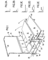
- a frame 10 which may be secured to the wall of a room. Connected to the frame are a table 12 and a pair of benches 14 and 16 on either side thereof. A backrest 17 is provided for the bench 14 adjacent to the frame 10.
- the frame 10 comprises a pair of uprights 18, spaced slightly from the wall but adjacent to the wall, connected together at their upper ends by a horizontally extending member 20 which extends rearwardly to the wall and which may be connected to the wall.
- the horizontally extending member may extend between the uprights at a location intermediate their ends.
- the embodiment shown in Figure 2 may have a similar alternative.
- the table 12 is connected to the bottom of each upright by a linkage 22, each linkage comprising a first elongate frame 24 pivotally connected to the upright 18 at 25 and a second elongate frame 26 connected between the first frame 24 and the table 12.
- the bench 14 is supported from below by a support bar 30 which rests on the floor.
- the bench 14 is connected to the back rest 17, and the bench and back rest are connected to the frame 10.
- the bench 16 is connected to the frame 10 by a linkage 34 comprising a first elongate portion 36 pivotally connected to the frame 10 at 25 and a second elongate portion 38 extending between the first portion 36 and the bench 16.
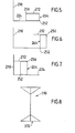
- the arrangement of the furniture shown in Figure 1 corresponds with the schematic illustration of a table having a pair of benches shown in Figure 2D.
- the bench 16 is the first position to be moved. Its linkage 34 includes a fixed pivot 40 and a locking pin 42 between the first and second elongate portions. The pin 42 is removed and the bench 16 is then lifted upwardly and rearwardly, as seen in Figure 1, in the anti-clockwise direction. The second elongate portion is also pivoted in an anti-clockwise direction about the fixed pivot 40 until the two portions lie alongside each other.
- the bench 16 is connected to the second elongate portion by fixed pivot 44 and locking pin 46, and the bench is rotated about the fixed pivot 44 until its upholstered side 48 faces the room. The bench is retained in this position by fixings (not shown) which co-operate between the frame 10 and the linkage 34 or the bench.
- the linkage 22 of the table 12 also includes a fixed pivot 50, 54 and a locking pin 52, 56 between the first and second elongate portions and the second elongate portion and the table respectively.
- the table can be moved to the position shown in Figure 2E, with the underside of the table facing the room and the first and second elongate portions lying alongside each other.
- the table is retained in this position by fixings (not shown) which co-operate between the frame 10 and the linkage or the table.
- the underside 58 of the table is upholstered and presents a generally planar surface in order to provide a bed, and this will be discussed in greater detail below, but in the position shown in Figure 2B, the underside presents a pleasing appearance.
- the backrest 17 is returned to the upright position and the support bar 30 for the bench 14 is swung up under the bench.
- the bench 14 can then be lowered so that its upholstered surface 62 faces the room.
- each of the benches, backrest and table In the fully retracted position the benches, backrest and table all extend generally parallel to the wall to present a compact configuration which takes up little space in the room. Furthermore, each of the benches, backrest and table present an upholstered surface to the room which affords a pleasing appearance.
- the second elongate portions 26 each comprise a pair of spaced parallel telescopic tubes 64 which can be collapsed so that their effective length allows the upholstered surface to be brought into line with the two benches.
- the double bed provided in Figure 2C may run away from the wall, or parallel to the wall.
- the backrest 17 can serve as a headboard for the bed and, if desired, can be upwardly and rearwardly inclined.
- the frame 110 includes a table 112, a bench 114 and a back rest 117. This configuration is also shown in Figure 4C. Unlike the embodiment described in Figure 1, there is no separate further bench 116 in addition to the backrest 117. Instead, the backrest 117 is connected to projections 166 extending from the base of the frame 110 by a pair of right angled supports 168. The backrest 117 can be moved to the position shown in phantom in Figure 3 (and in Figure 4F) by rotating the supports 168 clockwise about pivots 170 located at their connection with the projections 166.
- the reverse side of the backrest 117 is uppermost.
- This side can be upholstered, if desired, or the backrest may be pivotally mounted on the supports 168 to allow it to be reversed so that the side which forms the backrest also affords the seat.
- the table 110 can be rotated and lowered into the position shown in Figure 4D in which it comprises a 1 0 uble bed in a similar manner to that already described in relation to Figure 1.
- the double bed extends parallel to the wall.
- the table 110 can be moved to the retracted position and held there in a similar manner to that previously described in relation to Figure 1. This arrangement is shown in Figure 4B where the bench 114 may provide a seat or a single bed.
- the bench 114 can be moved into the retracted position by first removing the support 130 and then lowering the bench, as described in Figure 1, or by removing the support and raising the bench 114. The furniture arrangement is then in the fully retracted position shown in Figure 4A.
- the furniture arrangement may be moved from the configuration shown in Figure 4B, where a single bed or seat is provided by the bench 114, to the position shown in Figure 4E where the table 112 provides an upper bunk bed as follows.
- the telescopic tubes 164 are extended so that the fixed pivot 154 is raised.
- the locking pins 156 are then removed and the table rotated so that its upholstered side faces upwardly.
- the table is held in this position by locking means (not shown) co-operating between the frame 110 and the table.
- Each of the upholstered portions shown in the figures may be removable to allow them to be periodically cleaned.
- the linkage which is used to extend or retract the tables 12 and 112 and the benches 16 and 116 may also be used to extend or fold the benches 14 and 114.
- the table 212 is pivotally mounted at 256 on one corner of a rectangular support frame 264, the opposed corner being pivotally mounted at 252, which mounting 252. is also slidably mounted on a rail 224.
- the table 212 rests on the longer side of the support frame 264 and the upwardly facing surface of the table may be that of a table top, or upholstered to provide a bed (that is either a single bed on its own or a double bed in conjunction with another fitting (not shown).
- the rail 224 is pivotally connected to the frame to allow the table 212 to be swung to a higher position than that shown in Figure 7 in the vicinity of the frame.
- Figure 8 shows an end view of a frame 310 which may be used, which frame may either be self supporting, it having a broad base 370, or secured to an adjacent wall (not shown).
- the furniture shown described in the specification is particularly well suited to locations where space is limited such as in small rooms, caravans, dormobiles, prisons or oil rigs.
Landscapes
- Health & Medical Sciences (AREA)
- General Health & Medical Sciences (AREA)
- Nursing (AREA)
- Special Chairs (AREA)
- Combinations Of Kitchen Furniture (AREA)
Applications Claiming Priority (2)
| Application Number | Priority Date | Filing Date | Title |
|---|---|---|---|
| GB848429333A GB8429333D0 (en) | 1984-11-21 | 1984-11-21 | Furniture arrangements |
| GB8429333 | 1984-11-21 |
Publications (2)
| Publication Number | Publication Date |
|---|---|
| EP0182672A2 true EP0182672A2 (de) | 1986-05-28 |
| EP0182672A3 EP0182672A3 (de) | 1987-03-04 |
Family
ID=10570014
Family Applications (1)
| Application Number | Title | Priority Date | Filing Date |
|---|---|---|---|
| EP85308499A Withdrawn EP0182672A3 (de) | 1984-11-21 | 1985-11-22 | Verwandelbare Möbel |
Country Status (2)
| Country | Link |
|---|---|
| EP (1) | EP0182672A3 (de) |
| GB (1) | GB8429333D0 (de) |
Cited By (5)
| Publication number | Priority date | Publication date | Assignee | Title |
|---|---|---|---|---|
| GB2194732A (en) * | 1986-08-20 | 1988-03-16 | Andrew Keith Ruffle | Table |
| WO1991004694A1 (en) * | 1989-10-03 | 1991-04-18 | Joe Scott Hollingsworth | A furniture combination including a seat and a table with a table top and a supporting structure |
| GB2366720A (en) * | 2000-09-12 | 2002-03-20 | Martin John Donovan | Wall-mounted foldaway table and chairs |
| FR2879142A1 (fr) * | 2004-12-13 | 2006-06-16 | Christian Guttin | Dispositif d'amenagement interieur, notamment pour caravane, camping-car, mobile home ou analogue, transformable en espace nuit ou en espace jour |
| CN107095489A (zh) * | 2017-04-28 | 2017-08-29 | 长乐圆明工业设计有限公司 | 一种具有书桌与床之间相互切换功能的智能家具 |
Citations (5)
| Publication number | Priority date | Publication date | Assignee | Title |
|---|---|---|---|---|
| DE234864C (de) * | ||||
| GB602538A (en) * | 1945-10-16 | 1948-05-28 | Norman Sidney Avery | Improvements in chairs and like articles of furniture |
| FR1601456A (de) * | 1968-11-20 | 1970-08-24 | ||
| FR2248670A5 (en) * | 1973-10-18 | 1975-05-16 | Ruau Prosper | Double sided table for normal use or games - pivots to present required side uppermost and locked in plate |
| US3957302A (en) * | 1975-04-21 | 1976-05-18 | Jones Ferris E | Furniture combination |
-
1984
- 1984-11-21 GB GB848429333A patent/GB8429333D0/en active Pending
-
1985
- 1985-11-22 EP EP85308499A patent/EP0182672A3/de not_active Withdrawn
Patent Citations (5)
| Publication number | Priority date | Publication date | Assignee | Title |
|---|---|---|---|---|
| DE234864C (de) * | ||||
| GB602538A (en) * | 1945-10-16 | 1948-05-28 | Norman Sidney Avery | Improvements in chairs and like articles of furniture |
| FR1601456A (de) * | 1968-11-20 | 1970-08-24 | ||
| FR2248670A5 (en) * | 1973-10-18 | 1975-05-16 | Ruau Prosper | Double sided table for normal use or games - pivots to present required side uppermost and locked in plate |
| US3957302A (en) * | 1975-04-21 | 1976-05-18 | Jones Ferris E | Furniture combination |
Cited By (6)
| Publication number | Priority date | Publication date | Assignee | Title |
|---|---|---|---|---|
| GB2194732A (en) * | 1986-08-20 | 1988-03-16 | Andrew Keith Ruffle | Table |
| WO1991004694A1 (en) * | 1989-10-03 | 1991-04-18 | Joe Scott Hollingsworth | A furniture combination including a seat and a table with a table top and a supporting structure |
| GB2366720A (en) * | 2000-09-12 | 2002-03-20 | Martin John Donovan | Wall-mounted foldaway table and chairs |
| GB2366720B (en) * | 2000-09-12 | 2003-06-18 | Martin John Donovan | Wall mounted fold-away table and chairs |
| FR2879142A1 (fr) * | 2004-12-13 | 2006-06-16 | Christian Guttin | Dispositif d'amenagement interieur, notamment pour caravane, camping-car, mobile home ou analogue, transformable en espace nuit ou en espace jour |
| CN107095489A (zh) * | 2017-04-28 | 2017-08-29 | 长乐圆明工业设计有限公司 | 一种具有书桌与床之间相互切换功能的智能家具 |
Also Published As
| Publication number | Publication date |
|---|---|
| EP0182672A3 (de) | 1987-03-04 |
| GB8429333D0 (en) | 1985-01-03 |
Similar Documents
| Publication | Publication Date | Title |
|---|---|---|
| US4402096A (en) | Folding bed chair with detachable cushions | |
| US4925245A (en) | Device convertible into a chair, table, bed or stool | |
| US3743351A (en) | Laterally expandable couch | |
| US8375483B2 (en) | Daybeds and methods for converting daybeds | |
| US3636892A (en) | Convertible table | |
| US5440768A (en) | Combination bed and table | |
| US4506927A (en) | Convertible table, chair, and bed combination | |
| US4250977A (en) | Combined seat and step-ladder arrangement | |
| US5893182A (en) | Combination item of furniture and foldable sleeper bed | |
| US7017200B2 (en) | Convertible furniture | |
| US5280656A (en) | Convertible sofa/bed | |
| EP0182672A2 (de) | Verwandelbare Möbel | |
| US5913770A (en) | Folding sofa-bed frame | |
| US5160183A (en) | Combination table and leg rest for reclining chair | |
| US3829907A (en) | Bed accessory | |
| US3087442A (en) | Convertible coffee-dining table | |
| US3284812A (en) | Bed chesterfield | |
| US20230133923A1 (en) | Convertible murphy bed with storage | |
| CN213282703U (zh) | 落地座椅 | |
| US5038421A (en) | Sofabed | |
| HU213146B (en) | Seat convertible into a bed | |
| US20040187206A1 (en) | Convertible furniture assembly | |
| US4953242A (en) | Padded flare-back sofa | |
| CN214760176U (zh) | 一种多功能可折叠沙发桌 | |
| US2620492A (en) | Bed construction |
Legal Events
| Date | Code | Title | Description |
|---|---|---|---|
| PUAI | Public reference made under article 153(3) epc to a published international application that has entered the european phase |
Free format text: ORIGINAL CODE: 0009012 |
|
| AK | Designated contracting states |
Kind code of ref document: A2 Designated state(s): AT BE CH DE FR GB IT LI LU NL SE |
|
| PUAL | Search report despatched |
Free format text: ORIGINAL CODE: 0009013 |
|
| AK | Designated contracting states |
Kind code of ref document: A3 Designated state(s): AT BE CH DE FR GB IT LI LU NL SE |
|
| STAA | Information on the status of an ep patent application or granted ep patent |
Free format text: STATUS: THE APPLICATION IS DEEMED TO BE WITHDRAWN |
|
| 18D | Application deemed to be withdrawn |
Effective date: 19870907 |