EP0182530A2 - Kabel - Google Patents
Kabel Download PDFInfo
- Publication number
- EP0182530A2 EP0182530A2 EP85307990A EP85307990A EP0182530A2 EP 0182530 A2 EP0182530 A2 EP 0182530A2 EP 85307990 A EP85307990 A EP 85307990A EP 85307990 A EP85307990 A EP 85307990A EP 0182530 A2 EP0182530 A2 EP 0182530A2
- Authority
- EP
- European Patent Office
- Prior art keywords
- compound
- cable
- water blocking
- chamber
- thixotropic
- Prior art date
- Legal status (The legal status is an assumption and is not a legal conclusion. Google has not performed a legal analysis and makes no representation as to the accuracy of the status listed.)
- Withdrawn
Links
Images


Classifications
-
- H—ELECTRICITY
- H01—ELECTRIC ELEMENTS
- H01B—CABLES; CONDUCTORS; INSULATORS; SELECTION OF MATERIALS FOR THEIR CONDUCTIVE, INSULATING OR DIELECTRIC PROPERTIES
- H01B7/00—Insulated conductors or cables characterised by their form
- H01B7/17—Protection against damage caused by external factors, e.g. sheaths or armouring
- H01B7/28—Protection against damage caused by moisture, corrosion, chemical attack or weather
- H01B7/282—Preventing penetration of fluid, e.g. water or humidity, into conductor or cable
- H01B7/285—Preventing penetration of fluid, e.g. water or humidity, into conductor or cable by completely or partially filling interstices in the cable
-
- G—PHYSICS
- G02—OPTICS
- G02B—OPTICAL ELEMENTS, SYSTEMS OR APPARATUS
- G02B6/00—Light guides; Structural details of arrangements comprising light guides and other optical elements, e.g. couplings
- G02B6/44—Mechanical structures for providing tensile strength and external protection for fibres, e.g. optical transmission cables
- G02B6/4401—Optical cables
- G02B6/4429—Means specially adapted for strengthening or protecting the cables
- G02B6/44384—Means specially adapted for strengthening or protecting the cables the means comprising water blocking or hydrophobic materials
-
- H—ELECTRICITY
- H01—ELECTRIC ELEMENTS
- H01B—CABLES; CONDUCTORS; INSULATORS; SELECTION OF MATERIALS FOR THEIR CONDUCTIVE, INSULATING OR DIELECTRIC PROPERTIES
- H01B13/00—Apparatus or processes specially adapted for manufacturing conductors or cables
- H01B13/32—Filling or coating with impervious material
- H01B13/322—Filling or coating with impervious material the material being a liquid, jelly-like or viscous substance
- H01B13/323—Filling or coating with impervious material the material being a liquid, jelly-like or viscous substance using a filling or coating head
Definitions
- This invention relates to water blocking compositions, e.g. for use in cables, and to apparatus for the manufacture and use of such compositions.
- Water blocking compositions are commonly used in telecommunications cables to prevent the ingress of moisture. These compositions are generally highly viscous at ambient temperature and require heating prior to application to a cable. Since large cables have a high thermal mass it is not normally possible to apply the water blocking material in a single operation. Typically the material is applied to individual insulated conductors or fibres, or to groups of such components, which are subsequently stranded and sheathed to form the finished cable. The cable manufacturing process could of course be greatly improved if the application of the water blocking compound could be effected as a single operation on the stranded cable. Conventional hot filling processes have a number of inherent disadvantages. In particular the volume change on subsequent cooling can result in sufficient contraction to introduce voids in the cable.
- the object of the present invention is to minimise or to overcome these disadvantages.
- a water blocking compound for a cable the compound being hydrophobic and having thixotropic properties such that the viscosity of the compound may be temporarily reduced by mechanical shearing, characterised in that the compound includes a base fluid comprising a synthetic oil or a mixture of synthetic and mineral oils, and a thixotropic agent comprising a hydrophobic silica, bentonite or mixtures thereof.
- an apparatus for water blocking a cable with a thixotropic hydrophobic material including means for mechanically shearing the material, and means for injecting the sheared material into a cable.
- an applicator for applying a thixotropic water blocking material to an unsheathed cable, characterised in that the apparatus includes an elongate tubular chamber through which, in use, the cable is fed, that means are provided for supplying the compound under pressure to said chamber whereby the cable is filled with a compound, that a first pair of end seals provide sealing between the cable and the chamber whereby fluid pressure is maintained in the chamber, that a further pair of end seals define, with said first pair, secondary chambers one at each end of the tubular chamber, and that means are provided for removing excess compound from the secondary chambers.
- the materials described herein exhibit their thixotropic properties over a wide temperature range that includes ambient temperature.
- the materials retain their flexible properties and do not harden at service temperatures as low as -55 o C.
- a single water blocking material may be employed for arctic, temperate and tropical applications.
- hydrophobic properties of the base fluid could permit the use of a hydrophilic silica, e.g. of the type that has been employed as the thixotropic agent in greases and lubricants.
- a hydrophilic silica e.g. of the type that has been employed as the thixotropic agent in greases and lubricants.
- the silica is rendered hydrophobic by treating the surface of each particle with a siloxane. This provides a stable bond to the oils contained in the base fluid. It is thought that the siloxane acts as a coupling agent.
- the effect of the synthetic oil in the compound is to extend the temperature range, and in particular the low temperature range, of the material. Increasing the proportion of the synthetic oil in the base fluid lowers the minimum working temperature of the compound.
- the synthetic oil is fully compatible with the thixotropic agents employed herein. It will be appreciated by those skilled in the art that providing compatibility between a base fluid and a thixotropic thickener, particularly where a range of base fluid compositions is employed, can be difficult to achieve.
- the water blocking compositions include a synthetic hydrocarbon-based fluid which may contain an antioxidant of the same type as that used in the insulation of a cable that is to be filled.
- This base fluid is thickened to a gel by the addition of thickener comprising e.g. a hydrophobic grade of pyrogenic silica or bentonite or mixtures thereof.
- thickener comprising e.g. a hydrophobic grade of pyrogenic silica or bentonite or mixtures thereof.
- Fig. 1 of the accompanying drawings An apparatus for manufacturing the water blocking material is illustrated in Fig. 1 of the accompanying drawings.
- the component oils forming the base fluid are supplied from storage tanks (not shown) to a mixer tank 11 where the fluid is subjected to high shear at a temperature not exceeding 130°C for sufficient time to provide an homogeneous fluid.
- the fluid is transferred to a plough shear mixer 12, typically at a temperature not exceeding 80°C, and is mixed with the desired additives. Vacuum is then applied to the plough shear mixer 12 and a gel forming powder, e.g. silica or bentonite, is admitted through inlet 13. Vacuum is maintained during mixing to facilitate deaeration.
- a gel forming powder e.g. silica or bentonite
- the mixture thus formed may be transferred to a deaerater 14 and thence to a high pressure homogeniser 15. This develops the necessary thixotropic gel properties of the material by thorough dispersion of the powder thickener.
- the homogeniser may be replaced by a colloid mill or a ball mill. Finally the finished material is transferred from the homogeniser to a storage tank 16.
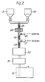
- FIG. 2 An apparatus for continuous processing of the water blocking material is shown in Fig. 2.
- the base fluid components are supplied from storage tanks 21, 22 via a static mixer 23 to a heat exchanger 24 where the temperature does not exceed 130°C.
- Additives are supplied via a first side entry tube 25 and are dispersed in a second static mixer 26.
- the thickening agent is auger fed via a second side entry tube 27 and the mix is passed through a third static mixer 28 to a homogeniser 29 where high shear is applied to disperse the thickener thus imparting thixotropic gel properties to the material.
- the homogenised material is then transferred via a deaerater 30 to a storage tank 31.
- the base fluid comprises a synthetic oil or mixtures of a synthetic oil and a mineral oil.
- the synthetic oil comprises at least 10% of the mixture.
- the quantity of synthetic oil in the mixture determines the service temperature range.
- the base fluid should consist solely of a synthetic oil.
- To 100 parts by weight of this base fluid is added 5 to 20 parts of a hydrophobic (fumed) silica or 2 to 10 parts of bentonite or equivalent mixtures thereof and, advantageously, up to 2 parts of a polarising agent, e.g. propylene carbonate and up to 1 part of an antioxidant/stabiliser.
- a polarising agent e.g. propylene carbonate
- the material may also include up to 10% and preferably not more than 5% of a polymeric dielectric stabiliser for which purpose we prefer to employ finely divided PTFE.
- a polymeric dielectric stabiliser for which purpose we prefer to employ finely divided PTFE.
- the thickener comprises 10 to 17 parts of silica based on the weight of the base fluid. In some applications the thickener may comprise 5 to 10 parts and advantageously 4 to 7 parts by weight of bentonite.
- the synthetic oil comprises a poly-a-olefin, e.g. SYNFLUID manufactured by the Gulf Oil Chemicals Company. This has a viscosity of 8 centistokes at 100°C.
- SYNFLUID manufactured by the Gulf Oil Chemicals Company.
- Other synthetic oils can of course be used.
- the synthetic oil may comprise a silicone oil.
- a particularly advantageous material has the following composition, all parts being quoted by weight:
- Dumb-bell test specimens in accordance with BS 2782, Method 320A were prepared from a typical MDPE and HDPE (medium density polyethylene and high density polyethylene) insulation polymer and immersed in the filling compounds for 14 days at 70°C. Also, dumb-bells were prepared from a Nylon 12 widely used for secondary coating of optical fibres. The resulting absorption of the compound by the polymer was determined together with its effect on polymer tensile properties.
- Oxidative induction time has been determined on 0.5/ 0.9 mm extruded insulation using the test procedure given in Section 3.10 of REA specification PE-39. This requires that the insulation is conditioned in the filling compound for 8 hours at 68 0 C prior to a Differential Scanning Calorimetry (DSC) measurement of OIT on a sample in a copper pan at 199°C, using in this case a DuPont 1090 Thermal Analyzer. Typical results are summarized in Table 3 below.
- Figs. 3 and 4 of the accompanying drawings An apparatus for this purpose is shown in Figs. 3 and 4 of the accompanying drawings.
- the water blocking material is supplied from a storage drum 41 via a pump 42, typically a positive displacement piston pump, to an in-line homogeniser or colloid mill 33.
- the mill exerts sufficient shear stress to break down the gel structure thus reducing the viscosity of the material which is then fed, preferably via a deaeration unit 34, to an applicator head 35 for injection into the cable.
- the head is shown in detail in Fig. 4 and is adapted to receive an unsheathed cable 36 to be filled.
- the blocking material is supplied under pressure via an inlet pipe 37 to a primary pressure chamber 38. This chamber is closed by seals 39, 40 through which the cable 36 is fed.
- a further pair of seals 61,62 define respective secondary or low pressure chambers 43,44, each of which has an outlet 45,46 whereby excess or unused blocking material is returned via a pipe 47 to the storage drum.
- the homogeniser may be dispensed with.
- the deaerater may be located in the return feed line to the storage tank.
- the gel structure is rapidly reformed and a permanent water block is provided. Also, as the gel properties are exhibited over a wide temperature range, the filled cable is suitable for arctic, temperate or tropical applications.
- FIG. 5 An alternative applicator head is shown in Fig. 5.
- the head comprises a tubular chamber 51 provided with a plurality of annular seals 52 through which the cable 36 is fed.
- the seals are a close fit on the cable and thus maintain fluid pressure in the central portion of the chamber 51.
- the water blocking material is supplied to the chamber 51 via an inlet 53 and surplus material is returned via outlets 54 disposed between the outer pairs of seals 52.
- the chamber 51 is of slightly larger diameter than the cable 36 so that, when the cable is drawn through the filled chamber a high shear is applied to the adjacent water blocking material thus breaking down its gel structure and lowering its viscosity. This then allows the material to penetrate the cable.
- the surplus material is passed through a deaerater before being returned to the storage tank.
- the material may be pumped as a gel into the applicator where its viscosity is reduced by the shearing action of the moving cable.
- the filling apparatus is arranged in tandem with a plastics extruder.
- the techniques described herein are employed with telecommunication cables but they may of course be extended to use with power cables.
- the compounds are particularly suitable for use with optical fibre cables, e.g. of the slotted core type, and as splice fillers.
Landscapes
- Physics & Mathematics (AREA)
- Engineering & Computer Science (AREA)
- Manufacturing & Machinery (AREA)
- General Physics & Mathematics (AREA)
- Optics & Photonics (AREA)
- Insulated Conductors (AREA)
- Sealing Material Composition (AREA)
- Addition Polymer Or Copolymer, Post-Treatments, Or Chemical Modifications (AREA)
- Lubricants (AREA)
- Manufacturing Of Electric Cables (AREA)
Applications Claiming Priority (2)
| Application Number | Priority Date | Filing Date | Title |
|---|---|---|---|
| GB8429077 | 1984-11-16 | ||
| GB848429077A GB8429077D0 (en) | 1984-11-16 | 1984-11-16 | Cables |
Publications (2)
| Publication Number | Publication Date |
|---|---|
| EP0182530A2 true EP0182530A2 (de) | 1986-05-28 |
| EP0182530A3 EP0182530A3 (de) | 1986-07-16 |
Family
ID=10569867
Family Applications (1)
| Application Number | Title | Priority Date | Filing Date |
|---|---|---|---|
| EP85307990A Withdrawn EP0182530A3 (de) | 1984-11-16 | 1985-11-04 | Kabel |
Country Status (13)
| Country | Link |
|---|---|
| EP (1) | EP0182530A3 (de) |
| JP (1) | JPS61126706A (de) |
| KR (1) | KR860004126A (de) |
| CN (1) | CN85109223A (de) |
| AU (1) | AU4987785A (de) |
| DK (1) | DK530385A (de) |
| ES (1) | ES8800496A1 (de) |
| FI (1) | FI854421A (de) |
| GB (2) | GB8429077D0 (de) |
| IL (1) | IL77033A0 (de) |
| IN (1) | IN164844B (de) |
| NO (1) | NO854583L (de) |
| ZA (1) | ZA858687B (de) |
Cited By (7)
| Publication number | Priority date | Publication date | Assignee | Title |
|---|---|---|---|---|
| EP0377314A2 (de) * | 1988-12-24 | 1990-07-11 | Minnesota Mining And Manufacturing Company | Verfahren zum Längsabdichten von Kabeln |
| EP0889343A2 (de) * | 1997-07-01 | 1999-01-07 | Lucent Technologies Inc. | Faseroptisches Kabel mit verbessertem Seelenfüllungsmaterial |
| US5902849A (en) * | 1991-11-07 | 1999-05-11 | Henkel Kommanditgesellschaft Auf Aktien | Filling compound |
| FR2774009A1 (fr) * | 1998-01-29 | 1999-07-30 | Elf Exploration Prod | Procede de preparation d'un melange injectable et gelifiable in situ dans un espace confine |
| US6258885B1 (en) | 1991-11-04 | 2001-07-10 | Henkel Kommanditgesellschaft Auf Aktien | Filling compound |
| WO2006034722A1 (en) * | 2004-09-27 | 2006-04-06 | Prysmian Cavi E Sistemi Energia S.R.L. | Optical cable for communication |
| US7995886B2 (en) | 2004-09-27 | 2011-08-09 | Prysmian Cavi E Sistemi Energia S.R.L. | Water-resistant optical cable and manufacturing method |
Families Citing this family (4)
| Publication number | Priority date | Publication date | Assignee | Title |
|---|---|---|---|---|
| GB8706459D0 (en) * | 1987-03-18 | 1987-04-23 | Ass Elect Ind | Mineral insulated electric cables |
| GB2248845B (en) * | 1990-10-17 | 1994-08-10 | Ass Elect Ind | A sealing composition and a mineral insulated electric cable termination employing such composition |
| KR100341972B1 (ko) * | 1999-06-08 | 2002-06-26 | 김충섭 | 통신케이블 접속부 밀봉형 젤 충전물과 이의 제조방법 |
| WO2020010537A1 (en) * | 2018-07-11 | 2020-01-16 | Dow Global Technologies Llc | Flooding composition with polytetrafluoroethyene |
Citations (6)
| Publication number | Priority date | Publication date | Assignee | Title |
|---|---|---|---|---|
| FR2152896A1 (de) * | 1971-09-13 | 1973-04-27 | Int Standard Electric Corp | |
| US3903013A (en) * | 1972-10-19 | 1975-09-02 | Int Standard Electric Corp | Water blocking gel composition |
| GB1427446A (en) * | 1974-01-16 | 1976-03-10 | Gen Cable Corp | Impregnation of multiconductor cables with solid filling compound |
| US3996413A (en) * | 1972-10-19 | 1976-12-07 | International Standard Electric Corporation | Sheathed stranded cable completely filled with water blocking composition |
| EP0067009A1 (de) * | 1981-05-26 | 1982-12-15 | RAYCHEM CORPORATION (a California corporation) | Wasserabweisende Füllstoppe |
| US4366075A (en) * | 1972-12-29 | 1982-12-28 | Phillips Cables Limited | Composition for filling cables |
Family Cites Families (2)
| Publication number | Priority date | Publication date | Assignee | Title |
|---|---|---|---|---|
| BE793873A (fr) * | 1970-12-04 | 1973-05-02 | Int Standard Electric Corp | Perfectionnement a la fabrication des cables telephoniques |
| GB1369814A (en) * | 1971-03-08 | 1974-10-09 | Lucas Industries Ltd | Lubricants for use in electrical apparatus |
-
1984
- 1984-11-16 GB GB848429077A patent/GB8429077D0/en active Pending
-
1985
- 1985-11-01 GB GB08526943A patent/GB2167084A/en not_active Withdrawn
- 1985-11-04 EP EP85307990A patent/EP0182530A3/de not_active Withdrawn
- 1985-11-11 FI FI854421A patent/FI854421A/fi not_active IP Right Cessation
- 1985-11-12 IL IL77033A patent/IL77033A0/xx unknown
- 1985-11-13 ZA ZA858687A patent/ZA858687B/xx unknown
- 1985-11-13 IN IN942/DEL/85A patent/IN164844B/en unknown
- 1985-11-13 AU AU49877/85A patent/AU4987785A/en not_active Abandoned
- 1985-11-14 JP JP60255807A patent/JPS61126706A/ja active Pending
- 1985-11-15 NO NO854583A patent/NO854583L/no unknown
- 1985-11-15 ES ES548957A patent/ES8800496A1/es not_active Expired
- 1985-11-15 DK DK530385A patent/DK530385A/da not_active Application Discontinuation
- 1985-11-15 CN CN198585109223A patent/CN85109223A/zh active Pending
- 1985-11-16 KR KR1019850008584A patent/KR860004126A/ko not_active Application Discontinuation
Patent Citations (6)
| Publication number | Priority date | Publication date | Assignee | Title |
|---|---|---|---|---|
| FR2152896A1 (de) * | 1971-09-13 | 1973-04-27 | Int Standard Electric Corp | |
| US3903013A (en) * | 1972-10-19 | 1975-09-02 | Int Standard Electric Corp | Water blocking gel composition |
| US3996413A (en) * | 1972-10-19 | 1976-12-07 | International Standard Electric Corporation | Sheathed stranded cable completely filled with water blocking composition |
| US4366075A (en) * | 1972-12-29 | 1982-12-28 | Phillips Cables Limited | Composition for filling cables |
| GB1427446A (en) * | 1974-01-16 | 1976-03-10 | Gen Cable Corp | Impregnation of multiconductor cables with solid filling compound |
| EP0067009A1 (de) * | 1981-05-26 | 1982-12-15 | RAYCHEM CORPORATION (a California corporation) | Wasserabweisende Füllstoppe |
Cited By (14)
| Publication number | Priority date | Publication date | Assignee | Title |
|---|---|---|---|---|
| EP0377314A2 (de) * | 1988-12-24 | 1990-07-11 | Minnesota Mining And Manufacturing Company | Verfahren zum Längsabdichten von Kabeln |
| EP0377314A3 (de) * | 1988-12-24 | 1991-07-03 | Minnesota Mining And Manufacturing Company | Verfahren zum Längsabdichten von Kabeln |
| US6258885B1 (en) | 1991-11-04 | 2001-07-10 | Henkel Kommanditgesellschaft Auf Aktien | Filling compound |
| US5902849A (en) * | 1991-11-07 | 1999-05-11 | Henkel Kommanditgesellschaft Auf Aktien | Filling compound |
| EP0889343A3 (de) * | 1997-07-01 | 1999-10-06 | Lucent Technologies Inc. | Faseroptisches Kabel mit verbessertem Seelenfüllungsmaterial |
| EP0889343A2 (de) * | 1997-07-01 | 1999-01-07 | Lucent Technologies Inc. | Faseroptisches Kabel mit verbessertem Seelenfüllungsmaterial |
| AU737126B2 (en) * | 1997-07-01 | 2001-08-09 | Lucent Technologies Inc. | Optical fiber cable having an improved filling material within its core |
| EP0933124A1 (de) * | 1998-01-29 | 1999-08-04 | Elf Exploration Production | Verfahren zur Herstellung einer injizierbaren und in situ gelierbaren Mischung in einem geschlossenen Raum |
| FR2774009A1 (fr) * | 1998-01-29 | 1999-07-30 | Elf Exploration Prod | Procede de preparation d'un melange injectable et gelifiable in situ dans un espace confine |
| WO2006034722A1 (en) * | 2004-09-27 | 2006-04-06 | Prysmian Cavi E Sistemi Energia S.R.L. | Optical cable for communication |
| US7536071B2 (en) | 2004-09-27 | 2009-05-19 | Prysmian Cavi E Sistemi Energia S.R.L. | Optical cable for communication |
| CN100557471C (zh) * | 2004-09-27 | 2009-11-04 | 普雷斯曼电缆及系统能源有限公司 | 用于通讯的光缆 |
| AU2004323686B2 (en) * | 2004-09-27 | 2011-04-14 | Prysmian Cavi E Sistemi Energia S.R.L. | Optical cable for communication |
| US7995886B2 (en) | 2004-09-27 | 2011-08-09 | Prysmian Cavi E Sistemi Energia S.R.L. | Water-resistant optical cable and manufacturing method |
Also Published As
| Publication number | Publication date |
|---|---|
| ES548957A0 (es) | 1987-10-16 |
| ZA858687B (en) | 1986-07-30 |
| JPS61126706A (ja) | 1986-06-14 |
| GB8429077D0 (en) | 1984-12-27 |
| NO854583L (no) | 1986-05-20 |
| IN164844B (de) | 1989-06-10 |
| DK530385A (da) | 1986-05-17 |
| CN85109223A (zh) | 1986-05-10 |
| FI854421A0 (fi) | 1985-11-11 |
| ES8800496A1 (es) | 1987-10-16 |
| FI854421A (fi) | 1986-05-17 |
| DK530385D0 (da) | 1985-11-15 |
| AU4987785A (en) | 1986-05-22 |
| GB8526943D0 (en) | 1985-12-04 |
| GB2167084A (en) | 1986-05-21 |
| IL77033A0 (en) | 1986-04-29 |
| EP0182530A3 (de) | 1986-07-16 |
| KR860004126A (ko) | 1986-06-18 |
Similar Documents
| Publication | Publication Date | Title |
|---|---|---|
| EP0067009B1 (de) | Wasserabweisende Füllstoppe | |
| DE60111933T2 (de) | Gel zusammensetzungen | |
| US4464013A (en) | Filled optical fiber cables | |
| US4351913A (en) | Filling materials for electrical and light waveguide communications cables | |
| US4324453A (en) | Filling materials for electrical and light waveguide communications cables | |
| US4176240A (en) | Filled electrical cable | |
| EP0811864B1 (de) | Füllmasse für Lichtwellenleiterkabel | |
| EP0586158B1 (de) | Kabel mit wasserblockierendem Material | |
| US4509821A (en) | Filling material for electric cable | |
| US3996413A (en) | Sheathed stranded cable completely filled with water blocking composition | |
| DE2946027C2 (de) | Längswasserdichtes Lichtwellenleiterkabel und Verfahren zu seiner Herstellung | |
| CA1131009A (en) | Filled electrical cable | |
| EP0182530A2 (de) | Kabel | |
| US4333706A (en) | Filling materials for communications cable | |
| DE3522751C2 (de) | Kabelfüllmassen | |
| EP0653764B1 (de) | Gefüllte Nachrichtenkabel mit Temperaturstabilisierter gegenseitiger Kapazität | |
| DE2806510A1 (de) | Fuell- und traenkmasse fuer kabel | |
| GB2195642A (en) | Filled cables | |
| US3903013A (en) | Water blocking gel composition | |
| US4382821A (en) | Filling materials for communications cable | |
| EP0074714A2 (de) | Füllmittel für Kabel | |
| EP0732374A2 (de) | Wasserquellbare Zusammensetzungen | |
| EP0001713B1 (de) | Elektrische Kabel und Füllungen für diese | |
| DE2730555A1 (de) | Isoliermassen an elektrischen kabeln | |
| US3893839A (en) | Telephone cable filling composition |
Legal Events
| Date | Code | Title | Description |
|---|---|---|---|
| PUAI | Public reference made under article 153(3) epc to a published international application that has entered the european phase |
Free format text: ORIGINAL CODE: 0009012 |
|
| AK | Designated contracting states |
Kind code of ref document: A2 Designated state(s): AT BE CH DE FR IT LI LU NL SE |
|
| PUAL | Search report despatched |
Free format text: ORIGINAL CODE: 0009013 |
|
| AK | Designated contracting states |
Kind code of ref document: A3 Designated state(s): AT BE CH DE FR IT LI LU NL SE |
|
| RAP1 | Party data changed (applicant data changed or rights of an application transferred) |
Owner name: STC PLC |
|
| 17P | Request for examination filed |
Effective date: 19861222 |
|
| 17Q | First examination report despatched |
Effective date: 19880525 |
|
| STAA | Information on the status of an ep patent application or granted ep patent |
Free format text: STATUS: THE APPLICATION IS DEEMED TO BE WITHDRAWN |
|
| 18D | Application deemed to be withdrawn |
Effective date: 19890105 |
|
| RIN1 | Information on inventor provided before grant (corrected) |
Inventor name: JOINER, DUDLEY ARNOLD Inventor name: BURY, JOHN ROBERT IVOR Inventor name: SIMPSON, WALTER ERIC |