EP0182502A2 - Système pour l'administration de médicaments - Google Patents
Système pour l'administration de médicaments Download PDFInfo
- Publication number
- EP0182502A2 EP0182502A2 EP85307566A EP85307566A EP0182502A2 EP 0182502 A2 EP0182502 A2 EP 0182502A2 EP 85307566 A EP85307566 A EP 85307566A EP 85307566 A EP85307566 A EP 85307566A EP 0182502 A2 EP0182502 A2 EP 0182502A2
- Authority
- EP
- European Patent Office
- Prior art keywords
- drug
- chassis
- pressure plate
- combination
- control module
- Prior art date
- Legal status (The legal status is an assumption and is not a legal conclusion. Google has not performed a legal analysis and makes no representation as to the accuracy of the status listed.)
- Granted
Links
Images


Classifications
-
- A—HUMAN NECESSITIES
- A61—MEDICAL OR VETERINARY SCIENCE; HYGIENE
- A61M—DEVICES FOR INTRODUCING MEDIA INTO, OR ONTO, THE BODY; DEVICES FOR TRANSDUCING BODY MEDIA OR FOR TAKING MEDIA FROM THE BODY; DEVICES FOR PRODUCING OR ENDING SLEEP OR STUPOR
- A61M5/00—Devices for bringing media into the body in a subcutaneous, intra-vascular or intramuscular way; Accessories therefor, e.g. filling or cleaning devices, arm-rests
- A61M5/14—Infusion devices, e.g. infusing by gravity; Blood infusion; Accessories therefor
- A61M5/142—Pressure infusion, e.g. using pumps
- A61M5/145—Pressure infusion, e.g. using pumps using pressurised reservoirs, e.g. pressurised by means of pistons
- A61M5/1452—Pressure infusion, e.g. using pumps using pressurised reservoirs, e.g. pressurised by means of pistons pressurised by means of pistons
- A61M2005/14533—Pressure infusion, e.g. using pumps using pressurised reservoirs, e.g. pressurised by means of pistons pressurised by means of pistons cam actuated
-
- A—HUMAN NECESSITIES
- A61—MEDICAL OR VETERINARY SCIENCE; HYGIENE
- A61M—DEVICES FOR INTRODUCING MEDIA INTO, OR ONTO, THE BODY; DEVICES FOR TRANSDUCING BODY MEDIA OR FOR TAKING MEDIA FROM THE BODY; DEVICES FOR PRODUCING OR ENDING SLEEP OR STUPOR
- A61M2205/00—General characteristics of the apparatus
- A61M2205/12—General characteristics of the apparatus with interchangeable cassettes forming partially or totally the fluid circuit
- A61M2205/128—General characteristics of the apparatus with interchangeable cassettes forming partially or totally the fluid circuit with incorporated valves
Definitions
- the present invention relates generally to the delivery of drugs to patients, particularly to systems for providing drug delivery, and specifically, to systems for providing continuous drug delivery.
- Certain drugs rarely achieve their maximum therapeutic action through conventional injection techniques.
- the therapeutic activity of such a drug is improved considerably when it is delivered at controlled rates to maintain optimum drug concentration for a specific period.
- a greater dosage than necessary must be administered to keep the drug concentration within the effective therapeutic margin for the minimum period needed for treatment.
- the drug can be given at a precise rate that will keep the drug serum concentration within the therapeutic margin and out of the toxic range.
- Continuous drug delivery is assuming an ever increasing role in the treatment of acute and chronic illnesses. Many drugs reach their full potential only through precise delivery over an extended period of time.
- the present invention solves this and other needs by providing, in the preferred embodiment, a system for delivering a drug to a patient of a modular construction and including control and reservoir modules.
- the reservoir module is removably secured to the control module.
- the reservoir module includes a drug container and a member which allows passage of the drug from the container to the patient.
- the control module includes a member for forcing the passage of the drug from the container to the patient.
- the drug forcing member of the control module interacts with the drug passage member of the reservoir module for purposes of delivering a drug stored in the drug container to the patient at desired rates.
- the drug delivery system of the present invention can be secured to the patient and allows the patient to be ambulatory.
- the system includes an occlusion detector which interrupts the drug forcing member in the event of reduced fluid pressure in the drug passage member to the patient.
- the occlusion detector includes a switch attached to the control module which engages, interacts, and is activated by the drug passage member of the reservoir module.
- the system has in the preferred embodiment, a locking mechanism including a latch button and a locking bolt which engages a member connected to a module including the drug storage container.
- the latch button is rotatably and slideably mounted about a longitudinal axis in the control module.
- the locking bolt is rotatably received on an eccentric portion of the latch button. The locking bolt is prevented from sliding on the latch button and is also prevented from rotating with the latch button.
- the latch button has a first position wherein the locking bolt does not engage with the engaging member of the reservoir module, a second position located longitudinally from the first position and a third position located longitudinally from the first position and in a rotated position from the first and second positions allowing the locking bolt to engage with and place a force on the engaging member of the reservoir module.
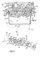
- System 10 is particularly adapted for securement to a patient such as by a belt allowing the patient to be ambulatory while having continuous infusion of a drug at the desired rate.
- System 10 in its most general preferred form includes a control module 12 and a reservoir module 14.
- Reservoir module 14 in its most preferred form includes a reservoir casing 16, a medicament container 18 shown in its most preferred form as a heat sealed vinyl bag, and a pressure plate 20. Bag 18 further includes a member 22 for providing communication between bag 18 and an infusion catheter of the patient and is shown in its most preferred form as an elastomeric tube.
- casing 16 is tub shaped and includes a generally closed bottom 24, a generally open top 26, and generally closed sidewalls 28-31.
- Pressure plate 20 in the preferred embodiment shown generally includes a flat portion 32 having a shape complementary to and for receipt in open top 26 of casing 16.
- Pressure plate 20 in its most preferred form includes hooked portions 34 which upstand from flat portion 32 at a first end thereof.
- pressure plate 20 further includes an inverted U-shaped member 36 upstanding from flat portion 32 at its end opposite to hooked portions 34.
- member 36 includes first and second legs 37 and 38 having their first ends connected to flat portion 32 and their second ends connected to a central portion 39 which is generally parallel to flat portion 32.
- Pressure plate 20 in the preferred embodiment shown further includes standoffs 40-43 upstanding from the top surface of flat portion 32 to a height for purposes set forth hereinafter.
- Standoffs 40-43 generally include first and second portions which extend between the sides of flat portion 32 and which are separated by a distance generally equal to the diameter of tube 22.
- Pressure plate 20 in the preferred embodiment shown further includes a trough portion 44 located between standoff 40 and the first end of plate 20 including hooked portions 34 having a size and shape complementary to and for receiving tube 22.
- tube 22 extends through an opening 46 formed in flat portion 32 adjacent member 36, extends between the first and second portions of standoffs 40-43, extends through trough portion 44, and through a removed portion 48 formed in the end of flat portion 32 adjacent hooked portions 34.
- tube 22 lies on flat portion 32 of pressure plate 20 generally midway between and parallel to the sides of flat portion 32.
- Tube 22 in the preferred embodiment of the present invention is secured to pressure plate 20 by a solvent bond located between tube 22 and trough portion 44 and is anchored by its other end to pressure plate 20 and reservoir module 14 by its securement to bag 18 captured between pressure plate 20 and casing 16 and its passage through opening 46 of pressure plate 20.
- Control module 12 in its most preferred form includes a casing 50 shown in its most preferred form formed of first and second halves and includes a generally closed top 52, a generally open bottom 54, and generally closed sidewalls 56-59.
- Control module 12 further includes a member 62 interacting with tube 22 for forcing liquid from bag 18 through tube 22 and for preventing free flow of liquid through tube 22 either to or from bag 18.
- Member 62 is shown in its most preferred form as a pumping mechanism.
- Pumping mechanism 62 includes a chassis 64 including a first flat portion 66 and a second flat portion 68 generally at right angles to each other.
- flat portion 68 has a shorter length than portion 66 and the ends of flat portion 68 are both spaced from the respective ends of portion 66.
- Chassis 64 further includes braces 70 and 72 which extend between portion 66 and the ends of portion 68 and which are spaced from each other and the ends of portion 66.
- Pumping mechanism 62 further includes in its most preferred form a camshaft 74 rotatably mounted between braces 70 and 72 and having a first cam portion 76 located between second and third cam portions 78 and 80 on shaft 74.
- Shaft 74 extends through brace 70 and further includes a driven gear 82 and an optical switch indicator 84 shown in its most preferred form as a flag located between the end of portion 66 and brace 70.
- pumping mechanism 62 further includes an expulsor 86 which is slideably mounted in an aperture 88 formed in portion 66.
- Expulsor 86 includes a head portion 92 including an arcuate portion 94 for engaging with cam portion 76 and an abutment surface 96 which prevents expulsor 86 from passing through aperture 88 of chassis 64.
- pumping mechanism 62 further includes first and second valves 100 and 102 which are slideably mounted in apertures 104 and 106 formed in portion 66 of chassis 64, respectively.
- Valves 100 and 102 each include a head portion 110 having an arcuate portion 112 for engaging with cam portions 78 and 80 and having an abutment surface 114 which prevents valves 100 and 102 from passing through apertures 104 and 106 of chassis 64.
- Provisions 90 are further provided for biasing expulsor 86 and valves 100 and 102 towards cam portions 76, 78, and 80 and for sealing expulsor 86 and valves 100 and 102 with flat portion 66 of chassis 64 of control module 12.
- provisions 90 is a closed cell foam gasket located in a cavity 98 formed in the top surface of flat portion 66 of chassis 64 and with which head portions 92 and 100 of expulsor 86 and valves 110 and 102 abut.
- Gasket 90 includes apertures 108 formed therein corresponding to apertures 88, 104, and 106 of chassis 64 and having a size and shape complementary to the receipt of expulsor 86 and valves 100 and 102.
- Gasket 90 has sufficient resiliency to bias expulsor 86 and valves 100 and 102 and has sufficient sealing ability to seal between chassis 64 and expulsor 86 and valves 100 and 102.
- pumping mechanism 62 further includes a member 118 for driving camshaft 74 shown as a motor mounted between braces 70 and 72.
- Motor 118 includes a drive shaft 120 which extends through brace 70 having a drive gear 122 in gearing relation with gear 82 of camshaft 74.
- motor 118 is a D.C. motor that rotates camshaft 74 through 360'degrees and then stops, with the number of rotations of shaft 74 controlling the volume of medicament being pumped from bag 18 of reservoir module 14.
- flat portion 66 of chassis 64 includes an upraised portion 124 located adjacent its first end having depending ears 126 extending therefrom. Hinge pins 128 are further provided extending between ears 126 generally parallel to flat portion 66. Hinge pins 128 are complementary to and for hingedly receiving hooked portions 34 of plate 20 of reservoir module 14.
- Flat portion 66 of chassis 64 further includes an aperture 130 located adjacent its opposite end complementary to and for receiving U-shaped member 36 of plate 20 of reservoir module 14.
- Control module 12 further includes a source of power for motor 118, such as a battery, and suitable electronic controls for the operation of motor 118 for controlling the pumping of the liquid from bag 18 through tube 22. Included with the electronic controls, control module 12 may include a liquid crystal display (LCD) 132 and switches or keys, generally designated 134, for purposes of programming the electronic controls to start or stop the pump, to vary the rate of pumping, for priming the pump, to limit patient operation of the pump, and like functions.
- LCD liquid crystal display
- programming modes of system 10 of the present invention may include: delivering drug concentrations of different rates; delivering a basal infusion at a set rate; allowing the patient the option of varying the basal rate up to the maximum rate allowed by the physician; delivering an incremental bolus dose at a set rate; allowing the patient the option of varying the incremental dose up to the maximum rate allowed by the physician; allowing the physician to set the minimum time between incremental doses; allowing the physician to limit the number of incremental doses per hour; and displaying the milligrams of medicament delivered, the number of incremental doses delivered, and the amount of volume of medicament remaining in the reservoir on the LCD 132.
- LCD 132 visually indicates various conditions of system 10 such as the rate oL pumping, the volume of liquid remaining in bag 18, and like conditions.
- LCD 132 and keys 134 are located in sidewall 56 of casing 50 of control module 12.
- the electronic controls may further include a user interaction signal such as a buzzer or other audible alarm for purposes of indicating the condition of system 10 such as indicating the pressing of keys 134, a low battery, an empty reservoir, an error in programming the electronic controls, or like condition.
- a manufacturer of a system according to the present invention would be in a position to program each system by modern electronics. That is, taking into account the above factors and other factors and constraints set by modern medicine and the laws of physics, a manufacturer can program each system to receive such variables as: patient dosage; medicament concentration; the medication schedule; the reservoir size; and other like considerations and can arrange the system to perform such functions as: dosage control; frequency of medication; variation of medication scheduling and dosage; various warnings and conditions, such as a low battery, error in programming the electronic controls, pressing of keys 134, and an empty reservoir; residential reservoir medication amount; and other like functions,for particular medications, particular patients, particular needs, etc.
- Casing 50 further includes an L-shaped casing portion 136 extending from sidewall 57 and between sidewalls 56 and 58.
- portion 136 includes a first leg 138 having a first end integrally connected to sidewall 57 and having a second end integrally connected to a second leg 140. The free end of leg 140 extends into open bottom 54 of casing 50.
- flat portion 66 of chassis 64 has a shape and size complementary to and for receipt in open bottom 54 of casing 50.
- Control module 12 further includes sealing members 142 located between the ends and sides of portion 66 of chassis 64 and sidewalls 56-69 of casing 50. Further, sealing member 144 is located between the free end of leg 140 of L-shaped casing portion 136 and the top surface of flat portion 66 of chassis 64.
- a substantially water tight compartment which includes motor 118, the electronic controls, the pumping mechanism 62, and other system components is defined by sidewalls 56-59, top 52, and L-shaped casing portion 136 of casing 50, flat portion 66 of chassis 64, expulsor 86, valves 100 and 102, gasket 90, and sealing members 142 and 144.
- the system components within this water tight compartment are protected from dust, the elements, or other contaminants which may produce damage thereto.
- Locking mechanism 146 generally includes, in the preferred embodiment, a latch guide'148, a latch button 150, a locking bolt 152, a pin 154; and a spring 156.
- Latch guide 148 generally includes a flat portion 158 which is captured between the halves of casing 50.
- a cylindrical member 160 is further provided depending from the end of flat portion 158 for rotatably and slideably receiving latch button 150.
- Ears 162 are provided on cylindrical member 160 for capturing between the halves of casing 50.
- a longitudinally extending, arcuate portion 164 is further provided on latch guide 148 depending from flat portion 158 and having a first end secured to cylindrical member 160.
- the second, free end of arcuate portion 164 includes a helical, camming portion 166 having stops 168 and 170 formed in and by arcuate portion 164.
- Camming portion 166 further includes a detent 172 formed adjacent stop 170 at the longitudinally inward end of camming portion 166.
- Latch button 150 generally includes a shank portion 174 which is rotatably and slideably received in cylindrical member 160 of latch guide 148 about its longitudinal axis and a head portion 176 which prevents shank portion 174 from passing through cylindrical member 160 in a first direction.
- Latch button 150 further includes an eccentric portion 178 which is eccentrically located with respect to the longitudinal axis of shank portion 174 and an extended shank portion 180.
- Locking bolt 152 generally includes a cylindrical portion 182 having a shape and size complementary to and for receipt on eccentric portion 176 of latch button 150.
- Locking bolt 152 further generally includes a T-shaped member 184 extending from cylindrical portion 182.
- T-shaped member 184 generally includes a leg member 185 having its first end connected to cylindrical portion 182 and its second end connected substantially to the middle of a cross member 186.
- Cross member 186 includes a first inner end.187 and a second, outer end 188.
- Cross member 186 includes a surface 189 located on the upper surface of cross member 186 between leg member 185 and end 187 for engaging with central portion 39 of U-shaped member 36 of pressure plate 20.
- Locking bolt 152 is held on eccentric portion 178 of latch button 150 in the preferred embodiment of the present invention between a shoulder formed between shank portion 174 and eccentric portion 178 and pin 154 extending through the extended shank portion 180 of latch button 150.
- Pin 154 further acts as the follower for camming portion 166 and for detent 172 of arcuate portion 164 of latch guide 148. Pin 154 also prevents shank portions 174 and 180 and eccentric portion 178 from passing through cylindrical member 160 in the opposite direction of head portion 176.
- pin 154 when latch button 150 is located at its first, extreme outward, unlocked position, pin 154 abuts with camming portion 166 adjacent stop 168 and end 188 of T-shaped member 184 of locking bolt 152 abuts with cylindrical member 160 of latch guide 148. Pin 154 further acts as an abutment for spring 158, with the spring 158 located concentrically on latch button 150 and extending between leg 140 of L-shaped casing portion 136 and pin 154. Thus, spring 158 biases latch button 150 in an outward direction.
- Locking mechanism 146 further includes provisions 190 for allowing the longitudinal movement of locking bolt 152 but preventing rotatable movement of locking bolt 152 with latch button 150. Provisions 190 are shown in the preferred embodiment of the present invention as tracks formed in the top surface of flat portion 66 of chassis 64 intermediate aperture 130 and its second end and having a shape complementary to and for slideable receipt of cross member 186 of T-shaped member 184 of locking bolt 152.
- Suitable provisions 191 for rotating latch button 150 may further be provided for locking mechanism 146.
- provisions 191 include a cavity 192 formed in head portion 176 of latch button 150 having a concentrically located, upstanding post 193.
- cavity 192 has a multisided perimeter, such as a hexagonal cross section and post 193 has a shape such as a circular cross section.
- Provisions 191 further includes a key 194 having a lug end 196 having a shape complementary to and for receipt within cavity 192, with the end 196 having a cavity 198 located generally concentrically therein.
- Cavity 198 has a size and shape complementary to and for receipt on post 193.
- locking mechanism 146 utilizing key 194 restricts the personnel who can unlock reservoir module 14 from control module 12. Specifically, keys 194 would be given only to physicians, pharmacists, and other authorized persons and not be given to patients utilizing system 10 or other unauthorized persons. Thus, without keys 194, the patients would be unable to rotate latch button 150 and release locking mechanism 146.
- provisions 191 may include an arcuate cavity formed in head portion 176 of latch button 150 for receiving the edge of a coin or similar object. Thus, by turning the coin, latch button 150 may be rotated.
- provisions 191 may take other forms according to the present invention.
- locking mechanism 146 can now be set forth and appreciated. For the sake of example, it will be assumed that U-shaped member 136 of pressure plate 20 is extending through aperture 130 of flat portion 66 of chassis 64 and latch button 150 is in its outward, unlocked position. To lock locking mechanism 146, latch button 150 may be pressed from its first position inwardly within latch guide 148 against the bias of spring 156 towards its second position. When latch button 150 is moved inwardly, locking bolt 152 secured thereto by pin 154 also moves inwardly, with surface 189 of cross member 186 of locking bolt 152 being located under the central portion 39 of U-shaped member 36 of pressure plate 20. At that time, latch button 150 may be rotated to its third position utilizing provisions 191.
- latch button 150 Due to the eccentric interaction between locking bolt 152 and latch button 150, rotation of latch button 150 causes locking bolt 152 to raise up engaging surface 189 with central portion 39. It should be noted that tracks 190 of chassis 64 prevent locking bolt 152 from rotating with latch button 150. Latch button 150 may be rotated until pin 154 abuts with stop 170 and is located within detent 172 of camming portion 166. At that time, due to its eccentric interaction, locking bolt 152 exerts an upward, locking force on central portion 39 of pressure plate 20. To enhance this exertion of an upward force, surface 189 and central portion 39 may include complementary, wedge- like tapers as in the most preferred form of the present invention. Further, with pin 154 located in detent 172, latch button 150 is prevented from accidentally rotating from its third, inward, locked position.
- latch button 150 is not located in its third position such that pin 154 is not located in detent 172, pin 154 under the bias of spring 156 will ride back upon camming portion 166 until stop 168.
- latch button 150 to which pin 154 is secured rotates and slides back to its first, unlocked position such that locking bolt 152 does not engage with U-shaped member 36.
- reservoir module 14 is not secured to control module 12. The reason for this subtle feature is to insure that partial engagement of locking bolt 152 with U-shaped member 36 does not occur.
- reservoir module 14 may be positioned in a first position with respect to control module 12 such that hooked portions 34 of pressure plate 20 engage with hinge pins 128 of chassis 64 of control module 12.
- reservoir module 14 is separable from the control module 12.
- Reservoir and control modules 12 and 14 may then be moved towards their second position such that hooked portions 34 of pressure plate 20 hook on hinge pins 128 of chassis 64 of control module 12.
- control module 12 and reservoir module 14 may be placed on a flat surface such that bottom 24 of casing 16 of reservoir module 14,rests upon the flat surface.
- Control module 12 may then be'pressed firmly in its second position such that U-shaped member 136 of pressure plate 20 of reservoir module 14 extends through aperture 130 of chassis 64 of control module 12.
- Locking mechanism 146 may then be locked by sliding and rotating latch button 150 in a manner set forth hereinbefore such that locking bolt 152 engages with and raises up central portion 39 of pressure plate 20.
- pin 154 is located within detent 172 of camming portion 166, reservoir module 14 is firmly locked in its second position on control module 12.
- reservoir module 14 is removably secured to control module 12 by a removable hinge member including hooked portions 34 and hinge pins 128 at one end and by locking mechanism 146 at its other end.
- Tube 22 extends between casing 16 of reservoir module 14 and casing 50 of control module 12 through removed portion 48 formed in pressure plate 20 and casing 16.
- reservoir module 14 securement procedure as set forth hereinbefore may be simply reversed.
- each cycle of the pumping mechanism 62 includes the following valve and expulsor positions. Specifically, in the at rest, stopped, or beginning of the pump cycle, valves 100 and 102 both are in their lowermost position depressing tube 22 and expulsor 86 is at its uppermost position and thus not depressing tube 22. This particular initial position has found to be particularly advantageous since valves 100 and 102 prevent flow through tube 22 in either direction. Further, the position of expulsor 86 beginning at this uppermost position reduces tube 22 deformation since tube 22 is not depressed by the relatively large area of expulsor 86 in the rest position. Further, the position of valve 100 beginning the initiation of its upward movement reduces the starting load on pumping mechanism 62 and thus reduces the size requirement 62 on motor 118 and the energy requirements for motor 118.
- expulsor 86 compresses tube 22 placing pressure on the medicament in tube 22 between valves 100 and 102. After a slight amount of pressure is placed on tube 22 by expulsor 86, valve 100 moves to its upper position allowing flow of medicament from tube 22 past valve 100. It can then be appreciated that placement of pressure on tube 22 before valve 100 opens substantially prevents back flow of liquid from tube 22 towards valve 102. Back flow of liquid from tube 22 towards valve 102 may cause blood to back up in the catheter of the patient to which tube 22 is connected.
- expulsor 86 Upon continued rotation of shaft 74, expulsor 86 continues its downward movement. Upon further rotation, expulsor 86 reaches its lowermost position and dwells in its lowermost position while valve 100 returns to its closed, lowermost position. This dwelling of expulsor 86 in its lowermost position also prevents back flow of medicament through tube 22 past valve 100.
- expulsor 86 starts in its upward movement. Just prior to expulsor 86 reaching its upper position, valve 102 starts in its upward movment. When expulsor 86 reaches its uppermost position, valve 102 also reaches its uppermost position. When camshaft 74 is continued in its rotation, valve 102 moves downward, while expulsor 86 dwells in its uppermost position.
- valve 102 Upon continued rotation of camshaft 74, valve 102 returns to its closed, lowermost position, expulsor 86 dwells at its uppermost position, valve 100 dwells at its lowermost position, and indicator 84 activates an optical switch causing the driving of shaft 74 by motor 118 to be stopped at the rest pump cycle.
- valves 100 and 102 engages with and compresses tube 22 against flat portion 32 of plate 20 at all times.
- accidental infusion of fluid through tube 22 such as under the influence of gravity or by compression of bag 18 is prevented.
- pumping mechanism 62 may rely on the recovery of tube 22 for maintaining contact of expulsor 86 and valves 100 and 102 with cam portions 76,.78, and 80, respectively, during the pumping cycle.
- gasket 90 or other biasing members may be utilized to assist expulsor and valve contact with cam portions 76, 78, and 80.
- the spacing between flat portion 32 of pressure plate 20 and flat portion 66 of chassis 64 has been found, thusfar, to be very important in maximizing the efficiency and advantageous operation of pumping mechanism 62. Specifically, it has been found that the travel distance of expulsor 86 and valves 100 and 102 through apertures 88, 104, and 106 of flat portion 66 is a constant system characteristic. Thus, if the spacing between pressure plate 20 and chassis 64 varies, disadvantageous operation of pumping mechanism 62 occurs. Specifically, if the spacing is too great, expulsor 86 and/or valves 100 and 102 may not compress tube 22 sufficiently or may not compress tube 22 at all.
- valves 100 and 102 may not prevent flow through of medicament through tube 22 in their lowermost, closed positions.
- expulsor 86 may not have sufficient stroke to compress tube 22 for forcing the desired amount of the medicament out of tube 22 past valve 100, thus greatly reducing efficiency and degrading the accuracy of system 10.
- tube 22 may not fully recover after compression to its uncompressed condition. This is very undesireable because this degrades the accuracy of system 10.
- the volume of medicament pumped by system 10 is directly related to the volume of,the tube being compressed by expulsor 86. If plastic deformation occurs to tube 22 due to over- compression by expulsor 86 and valves 100 and 102 of pumping mechanism 62, the volume compressed by expulsor 86 may change and thus change the volume of medicament being pumped by system 10.
- plate 20 is separable from chassis 64 due to their inclusion in separate modules 12 and 14.
- maintenance of the desired spacing between plate 20 and chassis 64 cannot be factory set but must be insured between control module 12 and a variety of reservoir modules 14 each having different tolerances.
- standoffs 40-43 are provided.
- standoffs 42 and 42 have a height generally equal to the desired spacing between plate 20 and chassis 64 and standoffs 40 and 43 have a height slightly less than the desired spacing between plate 20 and chassis 64.
- standoffs 40 and 43 act as safeguards to prevent pressure plate 20 and tube 22 mounted thereon from moving closer to chassis 64 at their respective locations when they abut therewith. Therefore, according to the present invention, the desired spacing of pressure plate 20 and tube 22 mounted thereon is insured to maximize system efficiency and its advantageous operation.
- standoffs 40-43 also insure that tube 22 is positioned on plate 20 for allowing engagement of expulsor 86 and valves 100 and 102 therewith. Further, tube 22 is held between and is prevented from moving between the first and second portions of standoffs 40-43 due to the abutment of standoffs 41 and 42 and the limited spacing of standoffs 40 and 43 from chassis 64.
- reservoir module 14 is secured to control module 12
- engagement of expulsor 86 and valves 100 and 102 with tube 22 is insured and tube 22 cannot move from between standoffs 40-43 during valve and expulsor engagement-to insure complete contact of valves 100 and 102 and expulsor 86 with tube 22 at all times.
- roller pumps strip the tubing causing the tubing to advance in the direction of rotation. This necessitates anchoring the tubing near the inlet to the roller pump head. Pumping mechanism 62 compresses tube 22 without pulling it so such anchoring is not required. Additionally, roller pumps require the tubing to be fully occluded. This complete occlusion stresses the tubing and distorts it such that the tubing does not fully recover.
- the expulsor 86 of pumping mechanism 62 shown need not fully occlude tube 22 and thus stresses in tube 22 may be limited to a level that does not yield unacceptable distortion.
- valves 100 and 102 for tube 22 of the present invention are believed advantageous over the use of passive check valves. Passive check valves are prone to allowing undesireable flow therethrough whereas valves 100 and 102 prevent flow through. It should be noted that if undesired flow occurs from the drug container to the patient, the rate of infusion is then not-controlled and precise delivery of the drug is not obtained. Further, excessive amounts of drug may be delivered to the patient. Additionally, it should also be noted that undesired flow from the patient towards the drug container may cause blood to back up the'catheter of the patient, which is medically undesireable.
- check valves will allow flow through by their nature in one direction whereas valves 100 and 102 of the present invention prevent flow through tube 22 in either direction.
- check valves would open and allow flow through towards the patient whereas valves 10U and 102 of the present invention will not allow such flow through.
- check valves have a high crack force which increases the pressure necessary for the pumping action.
- Valves 100 and 102 are independently driven so that there is no dependence of pressure generated by expulsor 86 such that reduced pumping pressure may be utilized in the present invention.
- check valves are unreliable in seating thus also allowing flow through whereas valves 100 and 102 are reliable in occluding tube 22 for preventing such flow through.
- active valves 100 and 102 are clearly advantageous over passive check valves.
- system 10 may be removably secured to the patient such as by a belt thus allowing the patient to be ambulatory while having a drug continuously administered.
- the patient need not be bedridden or have his freedom of movement otherwise restricted but may lead a relatively normal life.
- system 10 allows certain intravenous therapies to be given without frequent medical attention such as in a hospital environment but in an outpatient basis. Thus, health care costs may be significantly reduced.
- system 10 includes a modular construction featuring a removable reservoir module 14 is particularly advantageous.
- module 14 may be disposable such that,resterilization is not required therefor, and mistakes as to mixing of different medicaments in bag 18 and like mistakes are removed.
- reservoir module 14 provides increased protection against tampering of medicaments in bag 18 included within module 14.
- tube 22 with which pumping mechanism 62 engages is a component of and is replaced with each reservoir module 14. Thus, tube 22 which is most subject to wear and deformation is replaced with each refill greatly reducing the risk of equipment failure.
- control module 12 remains in a sealed compartment separate from reservoir module 14 and thus are not prone to accidental contact and damage when it becomes necessary to refill or replace bag 18. Further, no adjustments are required to insure proper and efficient operation of pumping mechanism 62 of the present invention when it is secured to any particular reservoir module 14.
- system 10 of the present invention and particularly standoffs 40-43, the hinge connection including hooked portions 34 and hinge pins 128, and locking mechanism 146 automatically insures the proper interrelation between control module 12 and all reservoir modules 14 utilized for efficient and advantageous operation of pumping mechanism 62.
- the modular construction of system 10 of the present invention is more user friendly than other prior drug delivery systems.
- System 10 as disclosed including a modular construction featuring a removable reservoir module 14, is further advantageous in its ability to include an occlusion detector 200 of a unique, simple, and generally fool proof nature.
- an occlusion detector 200 of a unique, simple, and generally fool proof nature.
- problems may result from the shortage of medication delivered to the patient.
- Such an occlusion might be caused, for example, by formation by a thrombus at the tip of an intravenous catheter, or by inadvertent failure to open a clamp applied to tube 22.
- occlusion detector 200 includes a pressure switch 202 located on chassis 64 of control module 12 of system 10 which abuts directly with tube 22 located on pressure plate 20 of reservoir module 14 when reservoir module 14 is secured to control module 12.
- a cavity 204 is provided on flat portion 66 of chassis 64 intermediate ears 126 and aperture 104.
- apertures 206 are provided which extend through flat portion 66 of chassis 64 for allowing passage of wires 208 and 210 of switch 202 therethrough.
- switch 202 is bonded to flat portion 66 of chassis 64 within cavity 204 by any suitable means such as by an expoxy bond, an adhesive, or the like.
- Suitable sealing means 211 such as silicon rubber may be provided within apertures 206,and around wires 208 and 210 to maintain a substantially water tight compartment for protecting the controls and components within control module 12 from dust, the elements, or other contaminants which may produce damage thereto. It can then be realized that cavity 204 allows the rapid placement of switch 202 on chassis 64 during production of control module 12 and thus lends itself to rapid, easy manufacture.
- switch 202 includes an annular, insulating washer 212 and first and second, diaphragm type, normally spaced contacts 214 and 216.
- Contacts 214 and 216 in their most preferred form are disc shaped having their outer perimeters embedded or otherwise fixed in an electrically, longitudinally spaced condition in annular washer 212.
- contact 216 may include a depression, as shown, for providing a circular contact area.
- switch 202 may be an ITT Schadow Disc Series Switch, Model ED. Wires 208 and 210 are electrically connected to contacts 214 and 216, respectively. It can then be appreciated that when contacts 214 and 216 are in their normally spaced condition, switch 202 is unactivated, i.e.
- control module 12 includes suitable provisions for interrupting operation of pumping mechanism 62 when switch 202 is in an activated condition and may include various other provisions, such as an audible alarm, a visual indication in a liquid crystal display, an override for switch 202, and the like.
- occlusion detector 200 When reservoir module 14 is secured to control module 12, tube 22 of reservoir module 14 overlies switch 202 of control module 12 such that washer 212 abuts with and partially compresses tube 22. If the fluid within tube 22 is not under pressure, tube 22 is in a relaxed and unexpanded condition such that tube 22 does not deflect contact 14 to touch contact 16 and with switch 202 not being activated. On the other hand, if the fluid within tube 22 is under sufficient pressure, tube 22 is in an expanded condition and deflects contact 14 to touch contact 16 activating switch 202.
- the amount of fluid pressure required in tube 22 to deflect contact 14 to touch contact 16 providing electrical connection depends on several factors including the spacing of switch 202 from pressure plate 20, the longitudinal thickness of washer 212, the spacing of contact 214 from the longitudinal end of washer 212, the spacing of contacts 214 and 216, the force required to deflect contact 214 into contact 216, and the like.
- prior infusion pumps included bladders or chamber members located within the pump which moved a piston or similar member which in turn actuated a switch. It can then be appreciated that the bladder or chamber member required special manufacture of the tube which delivers the medicant to the patient and also required the infusion pump to include a further multiplicity of parts which further increased the cost, complexity, and size of the infusion pump.
- Other prior infusion pumps included plungers having enlarged head portions which bore against the tube which delivered the medicant to the patient. It can then be appreciated that this approach also required the infusion pump to include a further multiplicity of parts which also increased its cost, complexity, and size.
- the present invention overcomes these deficiencies of the prior art by providing an occlusion detector 200 having switch 202 as part of control module 12 which directly acts upon tube 22 of reservoir module 14. Specifically, the proper interrelation between control module 12 and reservoir module 14 is insured by standoffs 40-43, the hinged connection including hooked portions 34 and hinge pins 128, and locking mechanism 146. Further, the proper interrelation of-tube 22 beneath switch 202 is insured by standoff 40 and removed portion 48. Thus, automatic and fool proof placement and maintenance of tube 22 in a location allowing direct and accurate activation of,switch 202 is created by the present invention.
- tube 22 is of a uniform construction in its outer and inner diameters and its material throughout its length from drug storage container 18 of reservoir module 14 to adjacent the patient and does not require any bladder, chamber member, or like specially manufactured portion as was required by prior infusion pumps.
- detector 200 of system 10 according to the teachings of the present invention does not require pistons, plungers, or the like as were required by prior infusion pumps.
- system 10 having an included occlusion detector 200 according to the teachings of the present invention is not of any increased physical size and is of a simple design which is easy to manufacture.
- detector 200 according to the teachings of the present invention is of a relatively low cost to manufacture as well as assemble.
- tube 22 with which switch 202 of detector 200 engages is a component of and is replaced with each reservoir module 14.
- tube 22 which is most subject to deformation and wear which may affect the accuracy of occlusion detector 200 is replaced with each medicant refill according to the teachings of the present invention, greatly reducing the risk of equipment failure.
- reservoir module 14 can be formed of casing 16 having different heights to accomodate various sizes of bags 18.
- pressure plate 20 can be adapted to support an external bag 18 which is not located in a generally closed casing 16.
Landscapes
- Health & Medical Sciences (AREA)
- Vascular Medicine (AREA)
- Engineering & Computer Science (AREA)
- Anesthesiology (AREA)
- Biomedical Technology (AREA)
- Heart & Thoracic Surgery (AREA)
- Hematology (AREA)
- Life Sciences & Earth Sciences (AREA)
- Animal Behavior & Ethology (AREA)
- General Health & Medical Sciences (AREA)
- Public Health (AREA)
- Veterinary Medicine (AREA)
- Infusion, Injection, And Reservoir Apparatuses (AREA)
Priority Applications (1)
| Application Number | Priority Date | Filing Date | Title |
|---|---|---|---|
| AT85307566T ATE60716T1 (de) | 1984-10-19 | 1985-10-18 | Medikamentenabgabesystem. |
Applications Claiming Priority (6)
| Application Number | Priority Date | Filing Date | Title |
|---|---|---|---|
| US06/663,051 US4565542A (en) | 1984-10-19 | 1984-10-19 | Locking mechanism for a drug delivery system |
| US06/663,050 US4559038A (en) | 1984-10-19 | 1984-10-19 | Drug delivery system |
| US06/769,879 US4650469A (en) | 1984-10-19 | 1985-08-27 | Drug delivery system |
| US769879 | 1985-08-27 | ||
| US663050 | 2000-09-15 | ||
| US663051 | 2003-09-15 |
Publications (3)
| Publication Number | Publication Date |
|---|---|
| EP0182502A2 true EP0182502A2 (fr) | 1986-05-28 |
| EP0182502A3 EP0182502A3 (en) | 1986-08-27 |
| EP0182502B1 EP0182502B1 (fr) | 1991-02-06 |
Family
ID=27418076
Family Applications (1)
| Application Number | Title | Priority Date | Filing Date |
|---|---|---|---|
| EP19850307566 Expired - Lifetime EP0182502B1 (fr) | 1984-10-19 | 1985-10-18 | Système pour l'administration de médicaments |
Country Status (3)
| Country | Link |
|---|---|
| EP (1) | EP0182502B1 (fr) |
| JP (1) | JPH0757241B2 (fr) |
| DE (1) | DE3581704D1 (fr) |
Cited By (13)
| Publication number | Priority date | Publication date | Assignee | Title |
|---|---|---|---|---|
| EP0293958A1 (fr) * | 1987-05-08 | 1988-12-07 | Spruyt-Hillen B.V. | Crayon à injection |
| FR2632529A1 (fr) * | 1988-06-14 | 1989-12-15 | Celsa Composants Electr Sa | Perfectionnements aux appareils d'injection de drogue a reservoir amovible |
| EP0354324A2 (fr) * | 1988-07-08 | 1990-02-14 | I-Flow Corporation | Pompe à perfusion programmable et portable fonctionnant avec des cartouches |
| EP0372863A2 (fr) * | 1988-12-02 | 1990-06-13 | Ivac Corporation | Fixation de sécurité commandée par le patient pour un système de perfusion de médicaments analgésiques |
| EP0398583A2 (fr) * | 1989-05-11 | 1990-11-22 | Bespak plc | Pompe pour utilisation biomédicale |
| US5205819A (en) * | 1989-05-11 | 1993-04-27 | Bespak Plc | Pump apparatus for biomedical use |
| US5807322A (en) * | 1994-03-21 | 1998-09-15 | Graseby Medical Limited | Pumping and pressure detection using flexible tubes |
| EP1751639A2 (fr) * | 2004-05-25 | 2007-02-14 | Sherwood Services, AG | Systeme de surveillance de debit pour appareil de regulation de debit |
| WO2007052277A1 (fr) * | 2005-11-07 | 2007-05-10 | Medingo Ltd. | Pompe de perfusion modulaire ambulatoire |
| US9408966B2 (en) | 1997-08-22 | 2016-08-09 | Deka Products Limited Partnership | System and method for drug preparation and delivery |
| WO2019155453A1 (fr) | 2018-02-11 | 2019-08-15 | Avoset Health Ltd. | Pompe à perfusion à course flexible |
| WO2021236608A1 (fr) * | 2020-05-20 | 2021-11-25 | Zyno Medical, Llc | Système de verrouillage de cartouche pour pompe médicale ambulatoire |
| US11890451B2 (en) | 2019-03-05 | 2024-02-06 | Eitan Medical Ltd. | Anti-free-flow valve |
Families Citing this family (1)
| Publication number | Priority date | Publication date | Assignee | Title |
|---|---|---|---|---|
| US5041086A (en) * | 1987-12-04 | 1991-08-20 | Pacesetter Infusion, Ltd. | Clinical configuration of multimode medication infusion system |
Citations (5)
| Publication number | Priority date | Publication date | Assignee | Title |
|---|---|---|---|---|
| EP0069350A1 (fr) * | 1981-07-04 | 1983-01-12 | TERUMO KABUSHIKI KAISHA trading as TERUMO CORPORATION | Appareil d'infusion médical |
| DE3138267A1 (de) * | 1981-09-25 | 1983-04-21 | Pfrimmer & Co Pharmazeutische Werke Erlangen Gmbh, 8520 Erlangen | Vorrichtung zur verabreichung enteraler ernaehrung |
| US4410322A (en) * | 1979-03-09 | 1983-10-18 | Avi, Inc. | Nonpulsating TV pump and disposable pump chamber |
| EP0110687A1 (fr) * | 1982-11-29 | 1984-06-13 | Oximetrix, Inc. | Dispositif portatif de perfusion de liquides |
| DE3343708A1 (de) * | 1982-12-08 | 1984-06-14 | Moog Inc., 14052 East Aurora, N.Y. | Verfahren und vorrichtung zum ausgeben eines infusionsmittels an einen koerper eines saeugers |
Family Cites Families (1)
| Publication number | Priority date | Publication date | Assignee | Title |
|---|---|---|---|---|
| JPS5631758A (en) * | 1979-08-24 | 1981-03-31 | Sharp Kk | Detector for clogging condition of flexible tube |
-
1985
- 1985-10-18 EP EP19850307566 patent/EP0182502B1/fr not_active Expired - Lifetime
- 1985-10-18 DE DE8585307566T patent/DE3581704D1/de not_active Expired - Lifetime
- 1985-10-19 JP JP60234391A patent/JPH0757241B2/ja not_active Expired - Lifetime
Patent Citations (5)
| Publication number | Priority date | Publication date | Assignee | Title |
|---|---|---|---|---|
| US4410322A (en) * | 1979-03-09 | 1983-10-18 | Avi, Inc. | Nonpulsating TV pump and disposable pump chamber |
| EP0069350A1 (fr) * | 1981-07-04 | 1983-01-12 | TERUMO KABUSHIKI KAISHA trading as TERUMO CORPORATION | Appareil d'infusion médical |
| DE3138267A1 (de) * | 1981-09-25 | 1983-04-21 | Pfrimmer & Co Pharmazeutische Werke Erlangen Gmbh, 8520 Erlangen | Vorrichtung zur verabreichung enteraler ernaehrung |
| EP0110687A1 (fr) * | 1982-11-29 | 1984-06-13 | Oximetrix, Inc. | Dispositif portatif de perfusion de liquides |
| DE3343708A1 (de) * | 1982-12-08 | 1984-06-14 | Moog Inc., 14052 East Aurora, N.Y. | Verfahren und vorrichtung zum ausgeben eines infusionsmittels an einen koerper eines saeugers |
Cited By (25)
| Publication number | Priority date | Publication date | Assignee | Title |
|---|---|---|---|---|
| EP0293958A1 (fr) * | 1987-05-08 | 1988-12-07 | Spruyt-Hillen B.V. | Crayon à injection |
| FR2632529A1 (fr) * | 1988-06-14 | 1989-12-15 | Celsa Composants Electr Sa | Perfectionnements aux appareils d'injection de drogue a reservoir amovible |
| EP0354324A2 (fr) * | 1988-07-08 | 1990-02-14 | I-Flow Corporation | Pompe à perfusion programmable et portable fonctionnant avec des cartouches |
| EP0354324A3 (fr) * | 1988-07-08 | 1990-10-03 | I-Flow Corporation | Pompe à perfusion programmable et portable fonctionnant avec des cartouches |
| EP0372863A2 (fr) * | 1988-12-02 | 1990-06-13 | Ivac Corporation | Fixation de sécurité commandée par le patient pour un système de perfusion de médicaments analgésiques |
| EP0372863A3 (en) * | 1988-12-02 | 1990-10-10 | Pacesetter Infusion Ltd | Patient-controlled analgesia security attachment for a medication infusion system |
| EP0398583A2 (fr) * | 1989-05-11 | 1990-11-22 | Bespak plc | Pompe pour utilisation biomédicale |
| EP0398583A3 (fr) * | 1989-05-11 | 1991-03-27 | Bespak plc | Pompe pour utilisation biomédicale |
| US5205819A (en) * | 1989-05-11 | 1993-04-27 | Bespak Plc | Pump apparatus for biomedical use |
| US5807322A (en) * | 1994-03-21 | 1998-09-15 | Graseby Medical Limited | Pumping and pressure detection using flexible tubes |
| US9408966B2 (en) | 1997-08-22 | 2016-08-09 | Deka Products Limited Partnership | System and method for drug preparation and delivery |
| EP1751639A4 (fr) * | 2004-05-25 | 2009-10-21 | Covidien Ag | Systeme de surveillance de debit pour appareil de regulation de debit |
| EP1751639A2 (fr) * | 2004-05-25 | 2007-02-14 | Sherwood Services, AG | Systeme de surveillance de debit pour appareil de regulation de debit |
| US9039679B2 (en) | 2005-11-07 | 2015-05-26 | Roche Diagnostics Operations, Inc. | Systems and methods for sustained medical infusion and devices related thereto |
| EP2332595A3 (fr) * | 2005-11-07 | 2011-09-07 | Medingo Ltd. | Pompe à perfusion portable modulaire |
| EP2283882A3 (fr) * | 2005-11-07 | 2011-09-07 | Medingo Ltd. | Pompe de perfusion modulaire ambulatoire |
| CN102813976A (zh) * | 2005-11-07 | 2012-12-12 | 梅丁格有限公司 | 模块化便携式输注泵 |
| US8562590B2 (en) | 2005-11-07 | 2013-10-22 | Medingo Ltd. | Systems and methods for sustained medical infusion and devices related thereto |
| WO2007052277A1 (fr) * | 2005-11-07 | 2007-05-10 | Medingo Ltd. | Pompe de perfusion modulaire ambulatoire |
| US7935104B2 (en) | 2005-11-07 | 2011-05-03 | Medingo, Ltd. | Systems and methods for sustained medical infusion and devices related thereto |
| WO2019155453A1 (fr) | 2018-02-11 | 2019-08-15 | Avoset Health Ltd. | Pompe à perfusion à course flexible |
| EP3749387A4 (fr) * | 2018-02-11 | 2021-11-10 | Eitan Medical Ltd. | Pompe à perfusion à course flexible |
| US11890451B2 (en) | 2019-03-05 | 2024-02-06 | Eitan Medical Ltd. | Anti-free-flow valve |
| WO2021236608A1 (fr) * | 2020-05-20 | 2021-11-25 | Zyno Medical, Llc | Système de verrouillage de cartouche pour pompe médicale ambulatoire |
| US11712512B2 (en) | 2020-05-20 | 2023-08-01 | Zyno Medical, Llc | Ambulatory medical pump cartridge locking system |
Also Published As
| Publication number | Publication date |
|---|---|
| DE3581704D1 (de) | 1991-03-14 |
| JPH0757241B2 (ja) | 1995-06-21 |
| EP0182502A3 (en) | 1986-08-27 |
| JPS61113466A (ja) | 1986-05-31 |
| EP0182502B1 (fr) | 1991-02-06 |
Similar Documents
| Publication | Publication Date | Title |
|---|---|---|
| US4650469A (en) | Drug delivery system | |
| US4559038A (en) | Drug delivery system | |
| US4565542A (en) | Locking mechanism for a drug delivery system | |
| EP0182502B1 (fr) | Système pour l'administration de médicaments | |
| CA1303928C (fr) | Systeme et appareil pour l'administration par le patient d'un agent benefique et trousse | |
| US4498843A (en) | Insulin infusion pump | |
| US4313439A (en) | Automated, spring-powered medicament infusion system | |
| US6544229B1 (en) | Linearly motile infusion pump | |
| US4443218A (en) | Programmable implantable infusate pump | |
| CA2038921C (fr) | Pompe portative pour l'administration de liquides therapeutiques | |
| US9387288B2 (en) | Dosage sensing unit with tactile feedback | |
| EP0275213B1 (fr) | Système d'infusion de médicaments | |
| JPH08509898A (ja) | 携行注入ポンプ | |
| WO2001085232A2 (fr) | Appareil et procede d'infusion intraveineuse de fluide | |
| US11904133B2 (en) | Infusion pump systems and methods for administration sets | |
| WO2013158431A1 (fr) | Dispositif d'administration de médicament comportant un système de cartouche multi-réservoir et procédés d'utilisation associés | |
| EP3402551A1 (fr) | Dispositif de perfusion | |
| US8444609B2 (en) | Implantable therapeutic substance delivery system with catheter access port block and method of use | |
| US20220354750A1 (en) | Automated oral compound administration system and method | |
| Webb | Contemporary comments on infusion pumps | |
| Nahata | New Delivery Methods for Intravenous Drugs |
Legal Events
| Date | Code | Title | Description |
|---|---|---|---|
| PUAI | Public reference made under article 153(3) epc to a published international application that has entered the european phase |
Free format text: ORIGINAL CODE: 0009012 |
|
| AK | Designated contracting states |
Kind code of ref document: A2 Designated state(s): AT BE CH DE FR GB IT LI LU NL SE |
|
| PUAL | Search report despatched |
Free format text: ORIGINAL CODE: 0009013 |
|
| AK | Designated contracting states |
Kind code of ref document: A3 Designated state(s): AT BE CH DE FR GB IT LI LU NL SE |
|
| 17P | Request for examination filed |
Effective date: 19861218 |
|
| RAP1 | Party data changed (applicant data changed or rights of an application transferred) |
Owner name: PHARMACIA DELTEC, INC. |
|
| 17Q | First examination report despatched |
Effective date: 19880901 |
|
| GRAA | (expected) grant |
Free format text: ORIGINAL CODE: 0009210 |
|
| AK | Designated contracting states |
Kind code of ref document: B1 Designated state(s): AT BE CH DE FR GB IT LI LU NL SE |
|
| PG25 | Lapsed in a contracting state [announced via postgrant information from national office to epo] |
Ref country code: NL Effective date: 19910206 Ref country code: LI Effective date: 19910206 Ref country code: CH Effective date: 19910206 Ref country code: BE Effective date: 19910206 Ref country code: AT Effective date: 19910206 |
|
| REF | Corresponds to: |
Ref document number: 60716 Country of ref document: AT Date of ref document: 19910215 Kind code of ref document: T |
|
| ET | Fr: translation filed | ||
| REF | Corresponds to: |
Ref document number: 3581704 Country of ref document: DE Date of ref document: 19910314 |
|
| ITF | It: translation for a ep patent filed |
Owner name: STUDIO TORTA SOCIETA' SEMPLICE |
|
| REG | Reference to a national code |
Ref country code: CH Ref legal event code: PL |
|
| NLV1 | Nl: lapsed or annulled due to failure to fulfill the requirements of art. 29p and 29m of the patents act | ||
| PLBE | No opposition filed within time limit |
Free format text: ORIGINAL CODE: 0009261 |
|
| STAA | Information on the status of an ep patent application or granted ep patent |
Free format text: STATUS: NO OPPOSITION FILED WITHIN TIME LIMIT |
|
| 26N | No opposition filed | ||
| EPTA | Lu: last paid annual fee | ||
| PGFP | Annual fee paid to national office [announced via postgrant information from national office to epo] |
Ref country code: LU Payment date: 19940901 Year of fee payment: 10 |
|
| EAL | Se: european patent in force in sweden |
Ref document number: 85307566.1 |
|
| REG | Reference to a national code |
Ref country code: FR Ref legal event code: CD |
|
| ITPR | It: changes in ownership of a european patent |
Owner name: CAMBIO RAGIONE SOCIALE;SIMS DELTEC INC. |
|
| PG25 | Lapsed in a contracting state [announced via postgrant information from national office to epo] |
Ref country code: LU Free format text: LAPSE BECAUSE OF NON-PAYMENT OF DUE FEES Effective date: 19951018 |
|
| REG | Reference to a national code |
Ref country code: GB Ref legal event code: IF02 |
|
| PGFP | Annual fee paid to national office [announced via postgrant information from national office to epo] |
Ref country code: GB Payment date: 20040915 Year of fee payment: 20 |
|
| PGFP | Annual fee paid to national office [announced via postgrant information from national office to epo] |
Ref country code: FR Payment date: 20041004 Year of fee payment: 20 |
|
| PGFP | Annual fee paid to national office [announced via postgrant information from national office to epo] |
Ref country code: SE Payment date: 20041005 Year of fee payment: 20 |
|
| PGFP | Annual fee paid to national office [announced via postgrant information from national office to epo] |
Ref country code: DE Payment date: 20041029 Year of fee payment: 20 |
|
| PG25 | Lapsed in a contracting state [announced via postgrant information from national office to epo] |
Ref country code: GB Free format text: LAPSE BECAUSE OF EXPIRATION OF PROTECTION Effective date: 20051017 |
|
| REG | Reference to a national code |
Ref country code: GB Ref legal event code: PE20 |
|
| EUG | Se: european patent has lapsed |