EP0182364A2 - Laundry washing machine - Google Patents
Laundry washing machine Download PDFInfo
- Publication number
- EP0182364A2 EP0182364A2 EP19850114720 EP85114720A EP0182364A2 EP 0182364 A2 EP0182364 A2 EP 0182364A2 EP 19850114720 EP19850114720 EP 19850114720 EP 85114720 A EP85114720 A EP 85114720A EP 0182364 A2 EP0182364 A2 EP 0182364A2
- Authority
- EP
- European Patent Office
- Prior art keywords
- pressostat
- liquid
- tub
- laundry
- laundering
- Prior art date
- Legal status (The legal status is an assumption and is not a legal conclusion. Google has not performed a legal analysis and makes no representation as to the accuracy of the status listed.)
- Granted
Links
Images

Classifications
-
- D—TEXTILES; PAPER
- D06—TREATMENT OF TEXTILES OR THE LIKE; LAUNDERING; FLEXIBLE MATERIALS NOT OTHERWISE PROVIDED FOR
- D06F—LAUNDERING, DRYING, IRONING, PRESSING OR FOLDING TEXTILE ARTICLES
- D06F39/00—Details of washing machines not specific to a single type of machines covered by groups D06F9/00 - D06F27/00
- D06F39/08—Liquid supply or discharge arrangements
- D06F39/083—Liquid discharge or recirculation arrangements
-
- D—TEXTILES; PAPER
- D06—TREATMENT OF TEXTILES OR THE LIKE; LAUNDERING; FLEXIBLE MATERIALS NOT OTHERWISE PROVIDED FOR
- D06F—LAUNDERING, DRYING, IRONING, PRESSING OR FOLDING TEXTILE ARTICLES
- D06F33/00—Control of operations performed in washing machines or washer-dryers
- D06F33/30—Control of washing machines characterised by the purpose or target of the control
- D06F33/32—Control of operational steps, e.g. optimisation or improvement of operational steps depending on the condition of the laundry
- D06F33/34—Control of operational steps, e.g. optimisation or improvement of operational steps depending on the condition of the laundry of water filling
-
- D—TEXTILES; PAPER
- D06—TREATMENT OF TEXTILES OR THE LIKE; LAUNDERING; FLEXIBLE MATERIALS NOT OTHERWISE PROVIDED FOR
- D06F—LAUNDERING, DRYING, IRONING, PRESSING OR FOLDING TEXTILE ARTICLES
- D06F2103/00—Parameters monitored or detected for the control of domestic laundry washing machines, washer-dryers or laundry dryers
- D06F2103/18—Washing liquid level
-
- D—TEXTILES; PAPER
- D06—TREATMENT OF TEXTILES OR THE LIKE; LAUNDERING; FLEXIBLE MATERIALS NOT OTHERWISE PROVIDED FOR
- D06F—LAUNDERING, DRYING, IRONING, PRESSING OR FOLDING TEXTILE ARTICLES
- D06F2105/00—Systems or parameters controlled or affected by the control systems of washing machines, washer-dryers or laundry dryers
- D06F2105/02—Water supply
-
- Y—GENERAL TAGGING OF NEW TECHNOLOGICAL DEVELOPMENTS; GENERAL TAGGING OF CROSS-SECTIONAL TECHNOLOGIES SPANNING OVER SEVERAL SECTIONS OF THE IPC; TECHNICAL SUBJECTS COVERED BY FORMER USPC CROSS-REFERENCE ART COLLECTIONS [XRACs] AND DIGESTS
- Y10—TECHNICAL SUBJECTS COVERED BY FORMER USPC
- Y10T—TECHNICAL SUBJECTS COVERED BY FORMER US CLASSIFICATION
- Y10T137/00—Fluid handling
- Y10T137/7287—Liquid level responsive or maintaining systems
- Y10T137/729—Washing machine cycle control
Definitions
- the invention relates to a laundry washing machine designed for efficiently laundering laundry of various kinds, at different amounts thereof charged into the washing drum and at different levels of the laundering liquid in the tub.
- a laundry washing machine having a laundering tub, a drum for containing the laundry, and a laundering liquid collector receptacle disposed at a position below the tub and communicating therewith, said collector receptacle being adapted to contain at least one filter element, one electric heater element and one thermostatic sensor adapted respectively to filter and heat the laundering liquid and to sense the temperature thereof.
- the collector receptacle is connected on the one hand to the discharge conduit of the machine through a conventional discharge pump, and on the other hand, to the laundering tub through a further conduit and an electric recirculation pump separate from or coaxial with said discharge pump, said electric recircultaion pump being provided with a suction port connected to said collector and an outlet port connected to said further conduit.
- the described machine is designed for carrying out "intensive” and “delicate” washing programs in the conventional manner, for laundering very dirty laundry,, such programs being carried out with the laundering liquid being at a normal level in the tub and with the recirculation pump inoperative throughout the entire program, as well as "intensive” washing programs for laundering less dirty laundry, such programs being carried out with the laundering liquid within the tub at a reduced level and with operation of the recirculation pump during certain phases of the programs, so that the laundering liquid is repeatedly recirculated from the collector receptacle through the additional conduit back to the tub.
- the described laundry washing machine is also provided with a first and a second group of pressostats or similar level control devices associated respectively to the "intensive" washing programs at reduced charge levels and to the "intensive" washing programs at normal charge levels of the laundering liquid in the tub, said pressostats being adapted to be individually activated by means of manually operated selector switches prior to initiating any washing program, depending on the respective amount of laundry charged into the drum.
- said first group may consist of three pressostats for controlling respectively washing programs for a full charge, one-half charge and one-quarter charge of laundry
- said second group may include two pressostats for controlling respective washing programs of a full charge and one-half charge of laundry.
- This laundry washing machine is additionally provided with one further pressostat which in relation to the above named pressostats is adjusted to a different liquid level in the tub for controlling the above mentioned "delicate" washing programs.
- the selection of each washing program of the described machine requires the manual intervention of the user in the form of selective operation of the above named switches.
- the pressostats may be used for controlling washing programs of the type described with different charges of laundry in the drum other than the ones referred to above. In these cases, it is also possible to achieve efficient laundering of the laundry, although without obtaining optimum consumtion of waetr, electric energy and detergents.
- the laundry washing machine under discussion is substantially identical to the one descibed in Italian Patent Application No. 45734-A/83, although in contrast thereto it is equipped with a reduced number of pressostats or similar level control means for determining various liquid charge levels in the tub commensurate with the amount of laundry charged into the drum.
- a laundry washing machine comprising a washing tub, a drum mounted for rotation in said tub, a laundering liquid collector receptacle disposed at a position belay said tub and communicating therewith, said collector be provided with at least one heater element and a thermostatic sensor adapted respectively to heat said laundering liquid and to sense the temperature thereof said collector furthermore being connected to said tub through at least one conduit and an electric recirculation pump, the latter being operable to establish repeated recirculation of said laundering liquid from said collector to said tub, the machine further comprising means for controlling the liquid charge level and a solenoid valve or similar means connected to the electric circuit of the machine.
- the machine is characterized in that said level control means include a first, a second, a third, and a fourth pressostat or similar level control means adapted to be selectively connected to said solenoid valve; said first and second pressostat being adjusted to respectively control the liquid charge in said tub at a predetermined level and in said collector, at a minimum level, said pressostats being further-adapted to be selectively connected to said heater element and said thermostatic sensor, and to control the energisation of said electric recirculation pump through the intermediate of said second pressostat exclusively; said third pressostat being adjusted to control the liquid charge in said tub at a further predetermined level below that controlled by said first pressostat for any type and amount of laundry introduced into said drum, said fourth pressostat being adjusted to control said liquid charge in said tub at a level above the ones controlled by said first and second pressostats.
- said level control means include a first, a second, a third, and a fourth pressostat or similar level control means adapted to be selectively connected to said sole
- the laundry washing machine under discussion comprises a housing 3, a washing tub 4 mounted in housing 3 in a per se known manner, and a drum 5 for containing the laundry and mounted for rotation in tub 4.
- a container 6 for containing the detergents to be used during a laundering cycle Disposed in the upper portion of the machine is a container 6 for containing the detergents to be used during a laundering cycle, said container being connected to the water supply circuit via a conduit 7 and a solenoid valve 8, and provided with a flexible conduit 9 connected to tub 4 for the supply thereto of water and detergents.
- the lower part of tub 4 is formed with an outlet 10 connected through a flexible conduit 11 to a collector receptacle 12 for the laundering liquid supplied thereto from tub 4, said collector being designed to accommodate a fine-mesh filter 13 or a similar filter element of conventional type.
- Filter element 13 is removably inserted into collector 12 at a position in the path of the laundering liquid proven- ient from tub 4 so as to retain any particulate matter entrained by the liquid in the course of the laundering process.
- Collector 12 is also connected to an upper portion of tub 4 via a conduit 16 communicating with an upper part of the collector, and an electric recirculation pump 17 disposed in coaxial alignment with a motor 18 of the machine and adapted to be driven by the latter for repeatedly recirculating the laundering liquid from collector 12 to tub 4 during certain washing programs of the laundry washing machine.
- a discharge pump 19 collector 12 is finally connected to a flexible discharge conduit 20 provided for discharging the laundering liquid from the collector to the outside at the end of a given washing program.
- the laundry washing machine is substantially identical to the one described in Italian Patent Application 45734-A/83 filed by the present applicant on June 12, 1983, wherein the various operating modes and possible modifications of the laundry washing machine are described in detail.
- pressostat 21 is adjusted to control a minimum liquid charge level within collector 12. This minimum level is the same for any amount and/or type of laundry introduced into drum 5, and is selected so as to completely coevr heater element 14.
- the movable electric contact 27 of pressostat 21 is adapted to be switched to two operative positions into engagement with fixed contact 28 or fixed contact 29.
- Contact 28 is engaged when collector 12 is empty or has been filled with laundering liquid to a level below the minimum charge level.
- Contact 29 on the other hand is engaged when the liquid charge in collector 12 attains the minimum level (fig. 2).
- Pressostat 22 is adjusted to control the liquid charge within tub 4 at a predetermined level above the above noted minimum level, this level being substantially the same for any amount or type of laundry introduced into drum 5, with the purpose of soaking the laundry to a sufficient degree for ensuring satisfactory laundering.
- this pressostat is responsive to pressure variations occurring in recirculation conduit 16 as the laundering liquid passes therethrough during operation of recirculation pump 17.
- pressostat 22 has a movable contact 30 adapted to be switched to two operating positions into engagement with a fixed contact 31 or a fixed contact 32. Fixed contact 31 is engaged when the laundering liquid is not being recirculated through conduit 16, or is being recirculated at a rate below the one to which pressostat 22 is adjusted, due to the liquid being progressively absorbed by the laundry contained in drum 5.
- This pressostat is thus responsive to a zero pressure or reduced pressure of the liquid circulating through conduit 16, which pressure corresponds to a liquid level in tub 14 below the predetermined maximum level. Under these conditions, movable contact 30 remains in the above specified first position, causing additional liquid to be supplied to the tub of the machine.
- Movable contact 30 engages fixed contact 32 when the laundering liquid is being circulated through conduit 16 at the maximum rate to which pressostat 22 is adjusted. This condition is indicative of the laundry being soaekd to the required degree and results in that the supply of liquid to the tub is discontinued. Pressostat 22 thus responds to the maximum pressure of the liquid circulating through conduit 16, which pressure corresponds to the maximum liquid charge level within tub 4 and is dependent on the laundry introduced into the drum. Under these conditions movable contact 30 remains in the above specified second position.
- pressostat 22 is thus to control the amount of liquid supplied to the tub in accordance with the type of laundry and its liquid absorption capacity.
- the remaining pressostat 23 is adjusted to control the liquid charge within the tub at a further predetermined level above the one determined by second pressostat 22, regardless of the amount and kind of laundry introduced into drum 5.
- The-movable contact 33 of pressostat 23 (fig. 2) is adapted to be switched to two operating positions into engagement respectively with a fixed contact 34, when tub 4 is completely empty or filled with liquid to a level below the maximum level establisehd by pressostat 23, and a fixed contact 35 when the tub is filled with liquid up to the maximum level.
- pressostat 36 or similar level control means connected to air trap 26 of tub 4 and adjusted to control the liquid charge within tub 4 at a further predetermined level preferably above the one established by pressostat 22 and below the one established by pressostat 23.
- the electric circuit of the machine is adapted to be connected to the electric supply mains through a main switch 38, and includes, in addition to pressostats 21, 22, 23 and 36 and other components specified above, the windings 39 and 40 of motor 18 for enrgizing same at the lower laundering speed and a higher centrifuging speed, said windings being connected to respective starter capacitors 41 and 42.
- the circuit further includes a solenoid valve 43 or similar device controlling the liquid supply to the machine, and a motor 44 driving the program control unit.
- the program control unit is provided with a plurality of electric contacts 37, 45, 46, 47, 48, 49 and 50 operated by respective cams of the control unit for selectively energizing the various electric components of the machine in a manner to be described.
- contacts 45, 46, 47 and 49 are connected to a common electrical conductor 51 adapted to be selectively connected to a main supply conductor 52 of the circuit through either pressostat 21 or pressostat 36.
- movable contact 27 of pressostat 22 is connected to main conductor 52, while fixed contacts 28 and 29 are connected respectively to contact 48 of the program unit and to the above specified common conductor 51.
- movable contact 53 of pressostat 36 is likewise connected to main conductor 52, while its fixed contacts 54 and 55 are connected respectively to fixed contact 28 of pressostat 21 through contact 37 of the program unit, and to the other fixed contact 29 of pressostat 21.
- Program unit contact 48 may be connected to main conductor 52 through pressostats 22 and 23, respective fixed contacts 31 and 34 of which are interconnected in series, while the respective movable contacts 30 and 33 of these pressostats are connected respectively to main conductor 52 and contact 48. Contact 48 is thus supplied with current when movable contacts 30 and 33 are switched into engagement with fixed contacts 31 and 34, respectively.
- the two pressostats 22 and 23 are thus connected in series to one another, and in parallel to fixed contact 28 of pressostat 21 and fixed contact 54 of pressostat 36 through contact 37 of the program control unit.
- the remaining contact 50 of the program unit is directly connected to main conductor 52 and can be switched onto common conductor 51 by the action of the program control unit.
- the purpose of contact 50 is to keep program unit motor 44 always energized also during such phases of the washing program, during which the motor is not energized through one of the respective pressostats 21 and 36, i.e. when movable contacts 27 and 53, respectively, thereof, are in engagement with respective fixed contacts 28 and 54.
- contact 45 is adapted to close onto a circuit including heater element 14 and thermostatic sensor 15 interconnected in series and further connected to the other main conductor 56 of the electric circuit of the machine.
- Contact 47 may be switched onto one of fixed contacts 57 and 58 so as to selectively connect high-speed winding 40 with its associated capacitor 42 or low-speed winding 39 of motor 18 with its associated capacitor 41 to main conductor 56 through an inverter switch 59 for actuating motor 18 in alternate directions of rotation.
- contact 46 is adapted to be switched onto a fixed contact 60 connected to a further inverter switch 61 itself adapted to be switched onto one of fixed contacts 62 and 63 connected respectively to high-speed winding 40 and to inverter switch 59 by way of which low-speed winding 39 of motor 18 is to be energized in the manner described.
- Contact 48 of the program unit is adapted to be switched onto solenoid valve 43, itself connected to main conductor 56, while the remaining contact 49 is adapted to be switched onto one of fixed contacts 64 and 65 connected respectively to the motor 66 of recirculation pump 17 ' and to the motor 67 of discharge pump 19, each of said motors being connected to main conductor 56.
- the electric circuit of the present machine is thus composed of the same electric components connected to one another in the same manner as in the electric circuit described in the above quoted Italian Patent Application 45734-A/83.
- the present solution it is thus also possible to carry out "intensive" washing programs at normal laundering liquid levels for laundering cotton fabrics and high-temperature resistant synthetic fabrics when not excessively dirty, as well as "intensive” washing programs at reduced laundering liquid levels for laundering very dirty cotton fabrics and high-temperature resistant synthetic fabrics.
- the described solution also permits to carry out conventional "delicate" washing programs for laundering delicate synthetic fabrics and/or woolens.
- the machine according to the invention may also be equipped with suitable overflow prevention means for precluding the danger of excessive liquid charges in the machine.
- such overflow prevention means may include a further pressostat 68 or similar control means having a movable contact 69 connected to main conductor 52 and adapted to be switched onto one of fixed contacts 70 and 71, the latter one of which is connected to motor 67 of discharge pump 19.
- Pressostat 68 is in communication with the above mentioned air trap 26 so as to be responsive to the liquid level within the tub (fig. 1).
- Pressostat 68 is adjusted so as to maintain movable contact 69 in engagement with fixed contact 70 as long as the liquid level within the tub is below a predetermined maximum level, and to switch movable contact 69 onto fixed contact 71 when said maximum level is attained.
- This condition may be brought about for example by a malfunction of solenoid valve 43 and/or of other pressostats of the machine, such malfunction resulting in tub 4 being charged with liquid to an excessive level.
- the displacement of movable contact 69 of pressostat 68 into engagement with fixed contact 71 results in motor 67 of discharge pump 19 being energized so as to discharge the excessive amount of liquid supplied to the tub outside of the machine. Only after the liquid level within tub 4 has been thus reduced to below the maximum level, movable contact 69 is returned into engagement with fixed contact 70 so as to deenergize motor 67 of discharge pump 19.
- the electric circuit may advantageously be modified so as to include only two pressostats.
- one of the two pressostats may constitute a combination of pressostats 21 and 22 connected to the electric circuit of the machine in the manner shown in fig. 2 and communicating with a single air trap, for instance air trap 25 (fig. 1).
- the other of the two pressostats may then constitute a combination of pressostats 23, 36 and 68 connected to the electric circuit of the machine in the manner depicted in fig. 2 and communicating with air trap 26.
- the described machine is capable of carrying out "intensive" washing programs at normal,. and reduced laundering liquid levels in the tub with different amounts of laundry charged into the drum.
- the level of the laundering liquid introduced into the tub is determined by pressostat 36, while in the second case the liquid level is controlled by pressostats 21, 22 and 23 in the manner to be described.
- movable contact 53 of pressostat 36 is initially switched onto fixed contact 54, while contacts 37 and 48 of the program control unit are closed so as to energize solenoid valve 43, resulting in the supply of liquid to the tub of the machine.
- movable contact 53 of pressostat 36 is switched over to fixed contact 55 whereby to deenergize solenoid valve 43 and to supply current to contacts 45 - 49 of the program control unit.
- the laundering liquid is heated up to a maximum temperature of about 90 °C, and the drum is actuated at the laundering speed in alternate directions of rotation, and finally at the centrifuging speed by energizing the respective low-speed and high-speed windings 39 and 40 of motor 18 solely by way of contact 47 and inverter switch 59.
- contact 49 of the program unit is not actuated in this case for energizing motor 66 of recirculation pump 17.
- movable contact 27 of pressostat 21 is initially switched onto fixed contact 28, while contacts 45 and 48 of the program unit are actauted to close respectively the circuit of heater element 14 and thermostatic sensor 15, and the circuit of solenoid valve 43.
- Contact 37 of the program unit is in the open position, so that fixed contact 54 of pressostat 36 is disconnected from contact 48 of the program unit.
- Solenoid valve 43 is thus energized to admit liquid to collector receptacle 12 to a level controlled by pressostat 21 exclusively.
- movable contact 27 of pressostat 21 is switched over onto fixed contact 29, whereby to deenergize solenoid valve 43 and to apply a voltage to common conductor 51 including the respective contacts 45 - 49 of the program unit. This results in the heating of the laundering liquid contained in collector 12 being initiated. Subsequently the program unit continues to keep contact 45 in the closed position while switching contact 49 onto contact 64 for energizing motor 66 of recirculation pump 17, so that the laundering liquid is repeatedly recirculated from collector t2 to tub 4 through recirculation conduit 16.
- pressostat 22 will initially receive a minimum dynamic pressure of the liquid circulating in conduit 16, such pressure corresponding to a liquid level in the tub below the maximum level to which pressostat 22 is adjusted.
- movable contact 30 of pressostat 22 is switched onto fixed contact 31.
- Movable contact 33 of pressostat 23 is meanwhile in engagement with fixed contact 34, because this pressostat is adjusted to a higher liquid level in the tub than pressostat 22.
- pressostats 22 and 23 are connected to one another in series and to the circuit of solenoid valve 43, because the program unit maintains contact 48 in the position to close this circuit.
- pressostat 22 subsequently receives the maximum pressure of the liquid circulating in recirculation conduit 16, which pressure corresponds to the selected liquid level within the tub, its movable contact 30 is switched onto fixed contact 32 so as to deenergize solenoid valve 43 and to thus discontinue the supply of liquid to the machine.
- Tub 4 is now filled with the liquid to a level below the level determined by pressostat 36 for the above discussed "intensive" washing program.
- pressostat 22 permits the amount of water supplied to the tub to be - determined in accordance with the type and amount of the laundry contained in the drum. This is a considerable improvement over the solution protected by the above quoted Italian Patent Application No. 45734-A/83, according to which separate pressostats or similar control means are employed for determining the adequate liquid levels in the tub for each and any amount of laundry introduced into the drum.
- the laundering liquid is heated to a maximum temperature of about 90 °C, and the drum of the machine is rotated at the laundering speed in alternating directions of rotation, and at the centrifuging speed, for shorter durations than in the above discussed "intensive" washing programs.
- the rotation at the laundering and centrifuging speeds is brought about by switching contact 46 of the program unit onto fixed contact 60 and switching inverter switch 61 selectively onto fixed contacts 63 or 62.
- recirculation pump 17 is continuously energized so as to continuously recirculate the laundering liquid from collector 12 to tub 4 via conduit 16. During the entire washing program the laundry will thus be kept in a sufficiently soaked condition for preventing it from being damaged by the rotation of the drum.
- recirculation pump 17 is deenergized, and solenoid valve 43 is energized via movable contacts 30 and 33 of pressostats 22 and 23, respectively, and contact 48 of the program unit which is closed to complete the respective circuit.
- movable contact 33 of pressostat 23 is initially in engagement with fixed contact 34, while movable contact 30 of pressostat 21 engages fixed contact 31.
- the program unit of the machine actuates contact 48 to close the energizing circuit of solenoid valve 43 and keeps it in this position.
- movable contact 33 of pressostat 23 is switched to fixed contact 35 to deenergize solenoid valve 43 and to discontinue the supply of liquid to the tub.
- the rinsing steps are thus carried out in the conventional manner, discharge pump 19 being energized at the end of each rinsing step for discharging the liquid from tub 4 outside of the machine.
- the liquid is introduced into the machine together with the detergent, as in the case of the "intensive” washing programs, until the liquid attains the level determined by pressostat 23. Thereupon contact 33 of pressostat 23 is switched onto contact 35 so as to deenergize solenoid valve 43, while the program unit causes heater element 14 to be energized. Otherwise these programs are carried out in the conventional manner, with recirculation pump 17 remaining always deenergized and drum rotating motor 18 being actuated only at the low speed in alternate directions of rotation via contact 46 of the program unit and inverter switches 61 and 59.
- the machine according to the invention is thus capable of carrying out "intensive” and “delicate” washing programs of the conventional type, and in addition thereto, "intensive” washing programs with a reduced laundering liquid level in the tub.
- the later programs particularly permit the consumption of water, detergents and electric energy to be reduced with respect to conventional "intensive" washing programs.
- the respective consumptions may thus be optimized for any amount of laundry introduced into the drum.by adequately controlling the level of the laundering liquid supplied to the tub so as to correspondingly reducing the period of time required for heating the liquid.
- these operations are performed in a fully automatic manner with the aid of pressostats 21, 22 and 23 without the necessity of manually selecting the respective program for each charge of laundry introduced into the machine.
- a further advantage of the described machine results from the fact that the number of pressostats employed therein is reduced with respect to that of the pressostats employed in the anterior machine.
- pressostats 21 and 22 and pressostats 23, 36 and 68 are pressostats 21 and 22 and pressostats 23, 36 and 68, for executing the "intensive" washing programs with a reduced liquid level in the tub.
- pressostats may finally be connected to different portions respectively of recirculation conduit 16 and tub 4, without thereby leaving the scope of protection of the present invention.
Abstract
Description
- The invention relates to a laundry washing machine designed for efficiently laundering laundry of various kinds, at different amounts thereof charged into the washing drum and at different levels of the laundering liquid in the tub.
- In Italian Patent Application No. 45734-A/83, filed by the present applicant on June 12, 1983, there is described a laundry washing machine having a laundering tub, a drum for containing the laundry, and a laundering liquid collector receptacle disposed at a position below the tub and communicating therewith, said collector receptacle being adapted to contain at least one filter element, one electric heater element and one thermostatic sensor adapted respectively to filter and heat the laundering liquid and to sense the temperature thereof.
- The collector receptacle is connected on the one hand to the discharge conduit of the machine through a conventional discharge pump, and on the other hand, to the laundering tub through a further conduit and an electric recirculation pump separate from or coaxial with said discharge pump, said electric recircultaion pump being provided with a suction port connected to said collector and an outlet port connected to said further conduit.
- The described machine is designed for carrying out "intensive" and "delicate" washing programs in the conventional manner, for laundering very dirty laundry,, such programs being carried out with the laundering liquid being at a normal level in the tub and with the recirculation pump inoperative throughout the entire program, as well as "intensive" washing programs for laundering less dirty laundry, such programs being carried out with the laundering liquid within the tub at a reduced level and with operation of the recirculation pump during certain phases of the programs, so that the laundering liquid is repeatedly recirculated from the collector receptacle through the additional conduit back to the tub.
- In particular, these last-described "intensive" washing programs permit the consumption of water, detergents and electric energy to be considerably reduced with respect to the washing programs of which conventional laundry washing machines are capable.
- The described laundry washing machine is also provided with a first and a second group of pressostats or similar level control devices associated respectively to the "intensive" washing programs at reduced charge levels and to the "intensive" washing programs at normal charge levels of the laundering liquid in the tub, said pressostats being adapted to be individually activated by means of manually operated selector switches prior to initiating any washing program, depending on the respective amount of laundry charged into the drum.
- In particular, and merely by way of example, said first group may consist of three pressostats for controlling respectively washing programs for a full charge, one-half charge and one-quarter charge of laundry, while said second group may include two pressostats for controlling respective washing programs of a full charge and one-half charge of laundry. This laundry washing machine is additionally provided with one further pressostat which in relation to the above named pressostats is adjusted to a different liquid level in the tub for controlling the above mentioned "delicate" washing programs.
- Although the laundry washing machine of the above described design operates in a satisfactory manner,.there is the disadvantage that it requires numerous pressostats or similar liquid level control means for adjusting the liquid level in the tub to the different amounts of laundry charged into the drum.
- In addition, the selection of each washing program of the described machine requires the manual intervention of the user in the form of selective operation of the above named switches. On the other hand, the pressostats may be used for controlling washing programs of the type described with different charges of laundry in the drum other than the ones referred to above. In these cases, it is also possible to achieve efficient laundering of the laundry, although without obtaining optimum consumtion of waetr, electric energy and detergents.
- It is an object of the present invention to eliminate the above explained disadvantages and shortcomings in a laundry washing machine capable of carrying out the same washing programs as described above with reference to a known laundry washing machine, in a fully automatic manner and with any amount of laundry charged in the drum.
- According to the invention, the laundry washing machine under discussion is substantially identical to the one descibed in Italian Patent Application No. 45734-A/83, although in contrast thereto it is equipped with a reduced number of pressostats or similar level control means for determining various liquid charge levels in the tub commensurate with the amount of laundry charged into the drum.
- These and other objects are attained according to the invention by a laundry washing machine comprising a washing tub, a drum mounted for rotation in said tub, a laundering liquid collector receptacle disposed at a position belay said tub and communicating therewith, said collector be provided with at least one heater element and a thermostatic sensor adapted respectively to heat said laundering liquid and to sense the temperature thereof said collector furthermore being connected to said tub through at least one conduit and an electric recirculation pump, the latter being operable to establish repeated recirculation of said laundering liquid from said collector to said tub, the machine further comprising means for controlling the liquid charge level and a solenoid valve or similar means connected to the electric circuit of the machine.
- The machine is characterized in that said level control means include a first, a second, a third, and a fourth pressostat or similar level control means adapted to be selectively connected to said solenoid valve; said first and second pressostat being adjusted to respectively control the liquid charge in said tub at a predetermined level and in said collector, at a minimum level, said pressostats being further-adapted to be selectively connected to said heater element and said thermostatic sensor, and to control the energisation of said electric recirculation pump through the intermediate of said second pressostat exclusively; said third pressostat being adjusted to control the liquid charge in said tub at a further predetermined level below that controlled by said first pressostat for any type and amount of laundry introduced into said drum, said fourth pressostat being adjusted to control said liquid charge in said tub at a level above the ones controlled by said first and second pressostats.
- The characteristics and advantages of the invention will become more clearly evident from the following description, given by way of example with reference to the accompanying drawings, wherein
- fig. 1 shows a diagrammatic sectional view of a laundry washing machine in an embodiment of the invention, and
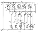
- fig. 2 shows an electric circuit diagram of the laundry washing machine according to the invention.
- With reference to fig. 1, the laundry washing machine under discussion comprises a
housing 3, awashing tub 4 mounted inhousing 3 in a per se known manner, and adrum 5 for containing the laundry and mounted for rotation intub 4. - Disposed in the upper portion of the machine is a
container 6 for containing the detergents to be used during a laundering cycle, said container being connected to the water supply circuit via aconduit 7 and asolenoid valve 8, and provided with aflexible conduit 9 connected totub 4 for the supply thereto of water and detergents. - The lower part of
tub 4 is formed with anoutlet 10 connected through aflexible conduit 11 to acollector receptacle 12 for the laundering liquid supplied thereto fromtub 4, said collector being designed to accommodate a fine-mesh filter 13 or a similar filter element of conventional type.Filter element 13 is removably inserted intocollector 12 at a position in the path of the laundering liquid proven- ient fromtub 4 so as to retain any particulate matter entrained by the liquid in the course of the laundering process. - Housed in the interior of
collector 12 are at least oneheater element 14 and athermostatic sensor 15 of conventional type adapted respectively to heat the laundering liquid supplied to the collector and to sense the temperature thereof. -
Collector 12 is also connected to an upper portion oftub 4 via aconduit 16 communicating with an upper part of the collector, and anelectric recirculation pump 17 disposed in coaxial alignment with amotor 18 of the machine and adapted to be driven by the latter for repeatedly recirculating the laundering liquid fromcollector 12 totub 4 during certain washing programs of the laundry washing machine. - Via a
discharge pump 19collector 12 is finally connected to aflexible discharge conduit 20 provided for discharging the laundering liquid from the collector to the outside at the end of a given washing program. - As far as described above, the laundry washing machine is substantially identical to the one described in Italian Patent Application 45734-A/83 filed by the present applicant on June 12, 1983, wherein the various operating modes and possible modifications of the laundry washing machine are described in detail.
- For controlling the liquid charge level in the described laundry washing machine, the latter is provided with three
pressostats air traps recirculation conduit 16 downstream ofrecirculation pump 17, the flow direction of the laundering liquid being indicated by arrows A, and to anair trap 26 provided at a lower portion oftub 4. In particular,pressostat 21 is adjusted to control a minimum liquid charge level withincollector 12. This minimum level is the same for any amount and/or type of laundry introduced intodrum 5, and is selected so as to completely coevrheater element 14. - The movable
electric contact 27 ofpressostat 21 is adapted to be switched to two operative positions into engagement with fixedcontact 28 or fixedcontact 29.Contact 28 is engaged whencollector 12 is empty or has been filled with laundering liquid to a level below the minimum charge level. Contact 29 on the other hand is engaged when the liquid charge incollector 12 attains the minimum level (fig. 2). - Pressostat 22 is adjusted to control the liquid charge within
tub 4 at a predetermined level above the above noted minimum level, this level being substantially the same for any amount or type of laundry introduced intodrum 5, with the purpose of soaking the laundry to a sufficient degree for ensuring satisfactory laundering. In particular, this pressostat is responsive to pressure variations occurring inrecirculation conduit 16 as the laundering liquid passes therethrough during operation ofrecirculation pump 17. As shown in fig. 2,pressostat 22 has amovable contact 30 adapted to be switched to two operating positions into engagement with a fixedcontact 31 or a fixedcontact 32. Fixedcontact 31 is engaged when the laundering liquid is not being recirculated throughconduit 16, or is being recirculated at a rate below the one to whichpressostat 22 is adjusted, due to the liquid being progressively absorbed by the laundry contained indrum 5. - This pressostat is thus responsive to a zero pressure or reduced pressure of the liquid circulating through
conduit 16, which pressure corresponds to a liquid level intub 14 below the predetermined maximum level. Under these conditions,movable contact 30 remains in the above specified first position, causing additional liquid to be supplied to the tub of the machine. -
Movable contact 30 engages fixedcontact 32 when the laundering liquid is being circulated throughconduit 16 at the maximum rate to whichpressostat 22 is adjusted. This condition is indicative of the laundry being soaekd to the required degree and results in that the supply of liquid to the tub is discontinued.Pressostat 22 thus responds to the maximum pressure of the liquid circulating throughconduit 16, which pressure corresponds to the maximum liquid charge level withintub 4 and is dependent on the laundry introduced into the drum. Under these conditionsmovable contact 30 remains in the above specified second position. - The purpose of
pressostat 22 is thus to control the amount of liquid supplied to the tub in accordance with the type of laundry and its liquid absorption capacity. - The
remaining pressostat 23 is adjusted to control the liquid charge within the tub at a further predetermined level above the one determined bysecond pressostat 22, regardless of the amount and kind of laundry introduced intodrum 5. - This liquid charge is exclusively used for rinsinf the laundry. The-
movable contact 33 of pressostat 23 (fig. 2) is adapted to be switched to two operating positions into engagement respectively with a fixedcontact 34, whentub 4 is completely empty or filled with liquid to a level below the maximum level establisehd bypressostat 23, and a fixedcontact 35 when the tub is filled with liquid up to the maximum level. - The machine under discussion is finally provided with a
further pressostat 36 or similar level control means connected toair trap 26 oftub 4 and adjusted to control the liquid charge withintub 4 at a further predetermined level preferably above the one established bypressostat 22 and below the one established bypressostat 23. - Turning now to fig. 2, it is noted that the electric circuit of the machine is adapted to be connected to the electric supply mains through a
main switch 38, and includes, in addition topressostats windings motor 18 for enrgizing same at the lower laundering speed and a higher centrifuging speed, said windings being connected torespective starter capacitors solenoid valve 43 or similar device controlling the liquid supply to the machine, and amotor 44 driving the program control unit. The program control unit is provided with a plurality ofelectric contacts - In particular,
contacts electrical conductor 51 adapted to be selectively connected to amain supply conductor 52 of the circuit through eitherpressostat 21 orpressostat 36. In the first case,movable contact 27 ofpressostat 22 is connected tomain conductor 52, while fixedcontacts common conductor 51. In the second case,movable contact 53 ofpressostat 36 is likewise connected tomain conductor 52, while itsfixed contacts contact 28 ofpressostat 21 throughcontact 37 of the program unit, and to the other fixedcontact 29 ofpressostat 21.Program unit contact 48 may be connected tomain conductor 52 throughpressostats fixed contacts movable contacts main conductor 52 and contact 48.Contact 48 is thus supplied with current whenmovable contacts fixed contacts - Under this condition, the two
pressostats contact 28 ofpressostat 21 and fixedcontact 54 ofpressostat 36 throughcontact 37 of the program control unit. Theremaining contact 50 of the program unit is directly connected tomain conductor 52 and can be switched ontocommon conductor 51 by the action of the program control unit. The purpose ofcontact 50 is to keepprogram unit motor 44 always energized also during such phases of the washing program, during which the motor is not energized through one of therespective pressostats movable contacts fixed contacts - The various connections adapted to be established by the electric contacts of the overall control circuit shall now be described in detail.
- In particular,
contact 45 is adapted to close onto a circuit includingheater element 14 andthermostatic sensor 15 interconnected in series and further connected to the othermain conductor 56 of the electric circuit of the machine. Contact 47 may be switched onto one offixed contacts speed winding 40 with its associatedcapacitor 42 or low-speed winding 39 ofmotor 18 with its associatedcapacitor 41 tomain conductor 56 through aninverter switch 59 for actuatingmotor 18 in alternate directions of rotation. In a corresponding manner,contact 46 is adapted to be switched onto a fixedcontact 60 connected to afurther inverter switch 61 itself adapted to be switched onto one offixed contacts speed winding 40 and toinverter switch 59 by way of which low-speed winding 39 ofmotor 18 is to be energized in the manner described. -
Contact 48 of the program unit is adapted to be switched ontosolenoid valve 43, itself connected tomain conductor 56, while theremaining contact 49 is adapted to be switched onto one offixed contacts motor 66 ofrecirculation pump 17'and to themotor 67 ofdischarge pump 19, each of said motors being connected tomain conductor 56. -
Motor 44 of the program control unit is finally connected directly betweencommon conductor 51 andmain conductor 56. With the exception ofpressostatss - Merely by way of example, such overflow prevention means may include a
further pressostat 68 or similar control means having amovable contact 69 connected tomain conductor 52 and adapted to be switched onto one of fixedcontacts motor 67 ofdischarge pump 19.Pressostat 68 is in communication with the above mentionedair trap 26 so as to be responsive to the liquid level within the tub (fig. 1). -
Pressostat 68 is adjusted so as to maintainmovable contact 69 in engagement with fixedcontact 70 as long as the liquid level within the tub is below a predetermined maximum level, and to switchmovable contact 69 onto fixedcontact 71 when said maximum level is attained. This condition may be brought about for example by a malfunction ofsolenoid valve 43 and/or of other pressostats of the machine, such malfunction resulting intub 4 being charged with liquid to an excessive level. In this case, the displacement ofmovable contact 69 ofpressostat 68 into engagement with fixedcontact 71 results inmotor 67 ofdischarge pump 19 being energized so as to discharge the excessive amount of liquid supplied to the tub outside of the machine. Only after the liquid level withintub 4 has been thus reduced to below the maximum level,movable contact 69 is returned into engagement with fixedcontact 70 so as to deenergizemotor 67 ofdischarge pump 19. - Instead of employing five
pressostats pressostats - The other of the two pressostats may then constitute a combination of
pressostats air trap 26. - The various washing programs which the machine according to the invention is capable of carrying out shall now be described in detail.
- In particular, the described machine is capable of carrying out "intensive" washing programs at normal,. and reduced laundering liquid levels in the tub with different amounts of laundry charged into the drum. In the first case, the level of the laundering liquid introduced into the tub is determined by
pressostat 36, while in the second case the liquid level is controlled bypressostats - For carrying out "intensive" washing programs at normal liquid levels in the tub,
movable contact 53 ofpressostat 36 is initially switched onto fixedcontact 54, whilecontacts solenoid valve 43, resulting in the supply of liquid to the tub of the machine. As the selected liquid level in the tub is attained,movable contact 53 ofpressostat 36 is switched over to fixedcontact 55 whereby to deenergizesolenoid valve 43 and to supply current to contacts 45 - 49 of the program control unit. During these washing programs, the laundering liquid is heated up to a maximum temperature of about 90 °C, and the drum is actuated at the laundering speed in alternate directions of rotation, and finally at the centrifuging speed by energizing the respective low-speed and high-speed windings motor 18 solely by way ofcontact 47 andinverter switch 59. On the other hand, contact 49 of the program unit is not actuated in this case for energizingmotor 66 ofrecirculation pump 17. - For carrying out "intensive" washing programs at reduced liquid level in the tub,
movable contact 27 ofpressostat 21 is initially switched onto fixedcontact 28, whilecontacts heater element 14 andthermostatic sensor 15, and the circuit ofsolenoid valve 43.Contact 37 of the program unit is in the open position, so that fixedcontact 54 ofpressostat 36 is disconnected fromcontact 48 of the program unit.Solenoid valve 43 is thus energized to admit liquid tocollector receptacle 12 to a level controlled bypressostat 21 exclusively. - As the selected minimum liquid level in
collector receptacle 12 is attained,movable contact 27 ofpressostat 21 is switched over onto fixedcontact 29, whereby to deenergizesolenoid valve 43 and to apply a voltage tocommon conductor 51 including the respective contacts 45 - 49 of the program unit. This results in the heating of the laundering liquid contained incollector 12 being initiated. Subsequently the program unit continues to keepcontact 45 in the closed position while switchingcontact 49 ontocontact 64 for energizingmotor 66 ofrecirculation pump 17, so that the laundering liquid is repeatedly recirculated from collector t2 totub 4 throughrecirculation conduit 16. Under this condition, pressostat 22 will initially receive a minimum dynamic pressure of the liquid circulating inconduit 16, such pressure corresponding to a liquid level in the tub below the maximum level to which pressostat 22 is adjusted. In response to this pressure,movable contact 30 ofpressostat 22 is switched onto fixedcontact 31.Movable contact 33 ofpressostat 23 is meanwhile in engagement with fixedcontact 34, because this pressostat is adjusted to a higher liquid level in the tub thanpressostat 22. As a result, pressostats 22 and 23 are connected to one another in series and to the circuit ofsolenoid valve 43, because the program unit maintainscontact 48 in the position to close this circuit. - This results in further liquid being supplied to
collector 12 as the liquid is being absorbed by the laundry contained indrum 5, until the laundry is soaked to a sufficient degree for being efficiently laundered. When pressostat 22 subsequently receives the maximum pressure of the liquid circulating inrecirculation conduit 16, which pressure corresponds to the selected liquid level within the tub, itsmovable contact 30 is switched onto fixedcontact 32 so as to deenergizesolenoid valve 43 and to thus discontinue the supply of liquid to the machine. -
Tub 4 is now filled with the liquid to a level below the level determined bypressostat 36 for the above discussed "intensive" washing program. The presence ofpressostat 22, permits the amount of water supplied to the tub to be - determined in accordance with the type and amount of the laundry contained in the drum. This is a considerable improvement over the solution protected by the above quoted Italian Patent Application No. 45734-A/83, according to which separate pressostats or similar control means are employed for determining the adequate liquid levels in the tub for each and any amount of laundry introduced into the drum. During these washing programs, the laundering liquid is heated to a maximum temperature of about 90 °C, and the drum of the machine is rotated at the laundering speed in alternating directions of rotation, and at the centrifuging speed, for shorter durations than in the above discussed "intensive" washing programs. The rotation at the laundering and centrifuging speeds is brought about by switchingcontact 46 of the program unit onto fixedcontact 60 and switchinginverter switch 61 selectively onto fixedcontacts - In addition,
recirculation pump 17 is continuously energized so as to continuously recirculate the laundering liquid fromcollector 12 totub 4 viaconduit 16. During the entire washing program the laundry will thus be kept in a sufficiently soaked condition for preventing it from being damaged by the rotation of the drum. - At the end of the laundering phase,
recirculation pump 17 is deenergized, andsolenoid valve 43 is energized viamovable contacts pressostats - As a result, a further amount of liquid is supplied to
tub 4 for gradually cooling the liquid already contained therein gether with the laundry in preparation of the following rinsing steps, which may then be carried out without undesirably wrinkling the laundry. Subsequentlysolenoid valve 43 is deenergized, andmotor 67 ofdischarge pump 19 is energized for discharging all of the liquid contained in the tub to the exterior of the machine. - For the following rinsing steps,
movable contact 33 ofpressostat 23 is initially in engagement with fixedcontact 34, whilemovable contact 30 ofpressostat 21 engages fixedcontact 31. The program unit of the machine actuatescontact 48 to close the energizing circuit ofsolenoid valve 43 and keeps it in this position. As the liquid thus supplied totub 4 attains the predetermined level,movable contact 33 ofpressostat 23 is switched to fixedcontact 35 todeenergize solenoid valve 43 and to discontinue the supply of liquid to the tub. - The rinsing steps are thus carried out in the conventional manner,
discharge pump 19 being energized at the end of each rinsing step for discharging the liquid fromtub 4 outside of the machine. - For carrying out "delicate" washing programs, the liquid is introduced into the machine together with the detergent, as in the case of the "intensive" washing programs, until the liquid attains the level determined by
pressostat 23. Thereuponcontact 33 ofpressostat 23 is switched ontocontact 35 so as to deenergizesolenoid valve 43, while the program unit causesheater element 14 to be energized. Otherwise these programs are carried out in the conventional manner, withrecirculation pump 17 remaining always deenergized and drumrotating motor 18 being actuated only at the low speed in alternate directions of rotation viacontact 46 of the program unit and inverter switches 61 and 59. - The machine according to the invention is thus capable of carrying out "intensive" and "delicate" washing programs of the conventional type, and in addition thereto, "intensive" washing programs with a reduced laundering liquid level in the tub.
- The later programs particularly permit the consumption of water, detergents and electric energy to be reduced with respect to conventional "intensive" washing programs. The respective consumptions may thus be optimized for any amount of laundry introduced into the drum.by adequately controlling the level of the laundering liquid supplied to the tub so as to correspondingly reducing the period of time required for heating the liquid. According to--the invention, these operations are performed in a fully automatic manner with the aid of
pressostats pressostats pressostats recirculation conduit 16 andtub 4, without thereby leaving the scope of protection of the present invention.
Claims (9)
Priority Applications (1)
| Application Number | Priority Date | Filing Date | Title |
|---|---|---|---|
| AT85114720T ATE53407T1 (en) | 1984-11-20 | 1985-11-19 | WASHING MACHINE. |
Applications Claiming Priority (2)
| Application Number | Priority Date | Filing Date | Title |
|---|---|---|---|
| IT4572584 | 1984-11-20 | ||
| IT4572584A IT1181078B (en) | 1984-11-20 | 1984-11-20 | WASHING MACHINE |
Publications (3)
| Publication Number | Publication Date |
|---|---|
| EP0182364A2 true EP0182364A2 (en) | 1986-05-28 |
| EP0182364A3 EP0182364A3 (en) | 1987-11-04 |
| EP0182364B1 EP0182364B1 (en) | 1990-06-06 |
Family
ID=11257752
Family Applications (1)
| Application Number | Title | Priority Date | Filing Date |
|---|---|---|---|
| EP19850114720 Expired - Lifetime EP0182364B1 (en) | 1984-11-20 | 1985-11-19 | Laundry washing machine |
Country Status (6)
| Country | Link |
|---|---|
| US (1) | US4696171A (en) |
| EP (1) | EP0182364B1 (en) |
| AT (1) | ATE53407T1 (en) |
| DE (1) | DE3578084D1 (en) |
| ES (1) | ES8609545A1 (en) |
| IT (1) | IT1181078B (en) |
Cited By (6)
| Publication number | Priority date | Publication date | Assignee | Title |
|---|---|---|---|---|
| EP0278461A1 (en) * | 1987-02-10 | 1988-08-17 | INDUSTRIE ZANUSSI S.p.A. | Program control device for a laundry washing machine |
| EP0628653A1 (en) * | 1993-06-07 | 1994-12-14 | Bosch-Siemens HausgerÀ¤te GmbH | Automatically controlled washing machine |
| GB2287961A (en) * | 1994-04-01 | 1995-10-04 | Zanussi Elettrodomestici | Clothes washing machine with improved water recovery tank |
| DE4332225B4 (en) * | 1993-06-07 | 2006-09-28 | BSH Bosch und Siemens Hausgeräte GmbH | Automatically controlled washing machine |
| EP2228478A1 (en) * | 2009-03-09 | 2010-09-15 | Panasonic Corporation | Drum-type washer |
| EP2792779B1 (en) | 2013-04-18 | 2015-09-30 | Whirlpool Corporation | Method for washing laundry in a spray washing machine |
Families Citing this family (19)
| Publication number | Priority date | Publication date | Assignee | Title |
|---|---|---|---|---|
| US5385168A (en) * | 1991-05-03 | 1995-01-31 | Act Distribution, Inc. | Hot water demand appliance and system |
| US5233718A (en) * | 1992-01-02 | 1993-08-10 | Whirlpool Corporation | Tumble method of rinsing fabric in a horizontal axis washer |
| US5191668A (en) * | 1992-01-02 | 1993-03-09 | Whirlpool Corporation | Spin method of rinsing fabric in a horizontal axis washer |
| US5191669A (en) * | 1992-01-02 | 1993-03-09 | Whirlpool Corporation | Spin method of washing fabric in a horizontal axis washer |
| US5219370A (en) * | 1992-01-02 | 1993-06-15 | Whirlpool Corporation | Tumbling method of washing fabric in a horizontal axis washer |
| US5461742A (en) * | 1994-02-16 | 1995-10-31 | Levi Strauss & Co. | Mist treatment of garments |
| DE19935987A1 (en) * | 1999-07-30 | 2001-02-01 | Bsh Bosch Siemens Hausgeraete | Laundry treatment machine |
| DE10061238B4 (en) * | 2000-12-08 | 2005-11-24 | BSH Bosch und Siemens Hausgeräte GmbH | Fastening device for a water level controller |
| KR100487346B1 (en) * | 2002-11-26 | 2005-05-03 | 엘지전자 주식회사 | Control method for supplying and draining water for drum-type washing machine |
| JP4084694B2 (en) * | 2003-04-22 | 2008-04-30 | シャープ株式会社 | Washing machine |
| US20060169219A1 (en) * | 2005-02-01 | 2006-08-03 | Philip Yaghmai | Automatic dog washing system |
| EP2034078B1 (en) * | 2007-09-05 | 2011-02-16 | Whirlpool Corporation | Method for quickly assessing the amount of water to be loaded in a washing machine provided with a water recirculation system and washing machine capable of carrying out such method |
| KR20120129004A (en) * | 2011-05-18 | 2012-11-28 | 삼성전자주식회사 | Drain hose and washing machine having the same |
| US8490439B2 (en) | 2011-09-30 | 2013-07-23 | Electrolux Home Products, Inc. | Water recirculation and drum rotation control in a laundry washer |
| EP2703547A1 (en) * | 2012-08-29 | 2014-03-05 | Electrolux Home Products Corporation N.V. | Laundry washing machine |
| EP2703546A1 (en) | 2012-08-29 | 2014-03-05 | Electrolux Home Products Corporation N.V. | Laundry washing machine |
| US9758918B2 (en) * | 2012-09-28 | 2017-09-12 | Dongbu Daewoo Electronics Corporation | Washing machine |
| CN105986427B (en) * | 2015-01-27 | 2019-10-01 | 青岛海尔洗衣机有限公司 | A kind of washing machine double-ended draining pump |
| US11105032B2 (en) * | 2018-04-10 | 2021-08-31 | Haier Us Appliance Solutions, Inc. | Washing machine appliance and methods for operating the same in a calibration cycle |
Citations (4)
| Publication number | Priority date | Publication date | Assignee | Title |
|---|---|---|---|---|
| FR1341267A (en) * | 1962-01-11 | 1963-10-25 | Bosch Gmbh Robert | Electric motor washing machine with program control |
| FR1454336A (en) * | 1964-11-20 | 1966-07-22 | Electrolux Ab | Security device |
| FR2525645A1 (en) * | 1982-04-23 | 1983-10-28 | Thomson Brandt | Washing machine using spray wetting instead of sump immersion - to reduce water usage and heat input per kg laundry |
| EP0146719A2 (en) * | 1983-12-06 | 1985-07-03 | INDUSTRIE ZANUSSI S.p.A. | Laundry washing machine |
Family Cites Families (3)
| Publication number | Priority date | Publication date | Assignee | Title |
|---|---|---|---|---|
| US3133433A (en) * | 1962-05-24 | 1964-05-19 | Controls Co Of America | Automatic washing machine with pressure switch means |
| US4206780A (en) * | 1977-12-01 | 1980-06-10 | Robertshaw Controls Company | Pressure operated water level control device and temperature responsive unit therefor or the like |
| US4168615A (en) * | 1978-05-17 | 1979-09-25 | General Electric Company | Clothes washing machine with water recirculation |
-
1984
- 1984-11-20 IT IT4572584A patent/IT1181078B/en active
-
1985
- 1985-10-30 ES ES548379A patent/ES8609545A1/en not_active Expired
- 1985-11-19 EP EP19850114720 patent/EP0182364B1/en not_active Expired - Lifetime
- 1985-11-19 AT AT85114720T patent/ATE53407T1/en not_active IP Right Cessation
- 1985-11-19 DE DE8585114720T patent/DE3578084D1/en not_active Expired - Lifetime
- 1985-11-20 US US06/799,986 patent/US4696171A/en not_active Expired - Lifetime
Patent Citations (4)
| Publication number | Priority date | Publication date | Assignee | Title |
|---|---|---|---|---|
| FR1341267A (en) * | 1962-01-11 | 1963-10-25 | Bosch Gmbh Robert | Electric motor washing machine with program control |
| FR1454336A (en) * | 1964-11-20 | 1966-07-22 | Electrolux Ab | Security device |
| FR2525645A1 (en) * | 1982-04-23 | 1983-10-28 | Thomson Brandt | Washing machine using spray wetting instead of sump immersion - to reduce water usage and heat input per kg laundry |
| EP0146719A2 (en) * | 1983-12-06 | 1985-07-03 | INDUSTRIE ZANUSSI S.p.A. | Laundry washing machine |
Cited By (7)
| Publication number | Priority date | Publication date | Assignee | Title |
|---|---|---|---|---|
| EP0278461A1 (en) * | 1987-02-10 | 1988-08-17 | INDUSTRIE ZANUSSI S.p.A. | Program control device for a laundry washing machine |
| EP0628653A1 (en) * | 1993-06-07 | 1994-12-14 | Bosch-Siemens HausgerÀ¤te GmbH | Automatically controlled washing machine |
| DE4332225B4 (en) * | 1993-06-07 | 2006-09-28 | BSH Bosch und Siemens Hausgeräte GmbH | Automatically controlled washing machine |
| GB2287961A (en) * | 1994-04-01 | 1995-10-04 | Zanussi Elettrodomestici | Clothes washing machine with improved water recovery tank |
| GB2287961B (en) * | 1994-04-01 | 1997-11-19 | Zanussi Elettrodomestici | Clothes washing machine with improved water recovery tank |
| EP2228478A1 (en) * | 2009-03-09 | 2010-09-15 | Panasonic Corporation | Drum-type washer |
| EP2792779B1 (en) | 2013-04-18 | 2015-09-30 | Whirlpool Corporation | Method for washing laundry in a spray washing machine |
Also Published As
| Publication number | Publication date |
|---|---|
| ES548379A0 (en) | 1986-09-01 |
| ES8609545A1 (en) | 1986-09-01 |
| EP0182364A3 (en) | 1987-11-04 |
| IT8445725A0 (en) | 1984-11-20 |
| IT8445725A1 (en) | 1986-05-20 |
| IT1181078B (en) | 1987-09-23 |
| ATE53407T1 (en) | 1990-06-15 |
| EP0182364B1 (en) | 1990-06-06 |
| US4696171A (en) | 1987-09-29 |
| DE3578084D1 (en) | 1990-07-12 |
Similar Documents
| Publication | Publication Date | Title |
|---|---|---|
| EP0182364B1 (en) | Laundry washing machine | |
| EP0146719B1 (en) | Laundry washing machine | |
| US4794661A (en) | Process for the treatment of laundry in a washing machine | |
| US4711103A (en) | Controlling device for clothes washing machine | |
| EP0726349B1 (en) | Method of washing for washing machine | |
| EP1939349B1 (en) | Laundry machine and control method thereof | |
| US4175409A (en) | Clothes washing machine | |
| EP0742307A1 (en) | Drum type washing machine and washing method thereof | |
| US20140250607A1 (en) | Method for Washing Laundry in a Laundry Washing Machine | |
| US4637231A (en) | Clothes washing machine including a high detergent concentration wash cycle | |
| CN105849332A (en) | Laundry washing machine and method for controlling a laundry washing machine | |
| US4225992A (en) | Clothes washing method | |
| US4321809A (en) | Washing machine | |
| JP3314144B2 (en) | Dryer | |
| CA1258381A (en) | Washing machine | |
| EP0300295B1 (en) | A procedure for washing clothes, fabrics and similar materials and a machine to practice said procedure | |
| EP0452678B1 (en) | Control assembly for a combined laundry washing and drying machine | |
| JPH10211383A (en) | Drum type dryer/washing machine | |
| US3939673A (en) | Device for preventing unbalance in washing machines during spindrying | |
| EP0278461B1 (en) | Program control device for a laundry washing machine | |
| CA2035320C (en) | Automatic laundry washer of the rotating drum type | |
| EP0224776B1 (en) | Automatic washing machine with rotating drum | |
| CA1148375A (en) | Assured slow speed spin for fabric washing machine | |
| JP3761662B2 (en) | Drum washing machine | |
| JPS638387Y2 (en) |
Legal Events
| Date | Code | Title | Description |
|---|---|---|---|
| PUAI | Public reference made under article 153(3) epc to a published international application that has entered the european phase |
Free format text: ORIGINAL CODE: 0009012 |
|
| AK | Designated contracting states |
Kind code of ref document: A2 Designated state(s): AT BE CH DE FR GB IT LI LU NL SE |
|
| PUAL | Search report despatched |
Free format text: ORIGINAL CODE: 0009013 |
|
| AK | Designated contracting states |
Kind code of ref document: A3 Designated state(s): AT BE CH DE FR GB IT LI LU NL SE |
|
| RAP1 | Party data changed (applicant data changed or rights of an application transferred) |
Owner name: INDUSTRIE ZANUSSI S.P.A. |
|
| 17P | Request for examination filed |
Effective date: 19880329 |
|
| 17Q | First examination report despatched |
Effective date: 19890831 |
|
| ITF | It: translation for a ep patent filed |
Owner name: PROPRIA PROTEZIONE PROPR. IND. |
|
| GRAA | (expected) grant |
Free format text: ORIGINAL CODE: 0009210 |
|
| AK | Designated contracting states |
Kind code of ref document: B1 Designated state(s): AT BE CH DE FR GB IT LI LU NL SE |
|
| REF | Corresponds to: |
Ref document number: 53407 Country of ref document: AT Date of ref document: 19900615 Kind code of ref document: T |
|
| REF | Corresponds to: |
Ref document number: 3578084 Country of ref document: DE Date of ref document: 19900712 |
|
| ET | Fr: translation filed | ||
| PGFP | Annual fee paid to national office [announced via postgrant information from national office to epo] |
Ref country code: CH Payment date: 19901018 Year of fee payment: 6 |
|
| PGFP | Annual fee paid to national office [announced via postgrant information from national office to epo] |
Ref country code: BE Payment date: 19901026 Year of fee payment: 6 |
|
| PGFP | Annual fee paid to national office [announced via postgrant information from national office to epo] |
Ref country code: LU Payment date: 19901106 Year of fee payment: 6 |
|
| PG25 | Lapsed in a contracting state [announced via postgrant information from national office to epo] |
Ref country code: LU Free format text: LAPSE BECAUSE OF NON-PAYMENT OF DUE FEES Effective date: 19901130 |
|
| PGFP | Annual fee paid to national office [announced via postgrant information from national office to epo] |
Ref country code: NL Payment date: 19901130 Year of fee payment: 6 |
|
| EPTA | Lu: last paid annual fee | ||
| PLBE | No opposition filed within time limit |
Free format text: ORIGINAL CODE: 0009261 |
|
| STAA | Information on the status of an ep patent application or granted ep patent |
Free format text: STATUS: NO OPPOSITION FILED WITHIN TIME LIMIT |
|
| 26N | No opposition filed | ||
| ITTA | It: last paid annual fee | ||
| PG25 | Lapsed in a contracting state [announced via postgrant information from national office to epo] |
Ref country code: LI Effective date: 19911130 Ref country code: CH Effective date: 19911130 Ref country code: BE Effective date: 19911130 |
|
| BERE | Be: lapsed |
Owner name: INDUSTRIE ZANUSSI S.P.A. Effective date: 19911130 |
|
| PG25 | Lapsed in a contracting state [announced via postgrant information from national office to epo] |
Ref country code: NL Effective date: 19920601 |
|
| NLV4 | Nl: lapsed or anulled due to non-payment of the annual fee | ||
| REG | Reference to a national code |
Ref country code: CH Ref legal event code: PL |
|
| EAL | Se: european patent in force in sweden |
Ref document number: 85114720.7 |
|
| REG | Reference to a national code |
Ref country code: GB Ref legal event code: IF02 |
|
| PGFP | Annual fee paid to national office [announced via postgrant information from national office to epo] |
Ref country code: AT Payment date: 20041007 Year of fee payment: 20 |
|
| PGFP | Annual fee paid to national office [announced via postgrant information from national office to epo] |
Ref country code: FR Payment date: 20041010 Year of fee payment: 20 |
|
| PGFP | Annual fee paid to national office [announced via postgrant information from national office to epo] |
Ref country code: GB Payment date: 20041014 Year of fee payment: 20 |
|
| PGFP | Annual fee paid to national office [announced via postgrant information from national office to epo] |
Ref country code: SE Payment date: 20041020 Year of fee payment: 20 Ref country code: DE Payment date: 20041020 Year of fee payment: 20 |
|
| PG25 | Lapsed in a contracting state [announced via postgrant information from national office to epo] |
Ref country code: GB Free format text: LAPSE BECAUSE OF EXPIRATION OF PROTECTION Effective date: 20051118 |
|
| REG | Reference to a national code |
Ref country code: GB Ref legal event code: PE20 |
|
| EUG | Se: european patent has lapsed |