EP0181942B1 - Magnetic recording/reproducing apparatus - Google Patents
Magnetic recording/reproducing apparatus Download PDFInfo
- Publication number
- EP0181942B1 EP0181942B1 EP85902162A EP85902162A EP0181942B1 EP 0181942 B1 EP0181942 B1 EP 0181942B1 EP 85902162 A EP85902162 A EP 85902162A EP 85902162 A EP85902162 A EP 85902162A EP 0181942 B1 EP0181942 B1 EP 0181942B1
- Authority
- EP
- European Patent Office
- Prior art keywords
- head
- recording
- signal
- value
- speed
- Prior art date
- Legal status (The legal status is an assumption and is not a legal conclusion. Google has not performed a legal analysis and makes no representation as to the accuracy of the status listed.)
- Expired - Lifetime
Links
Images


Classifications
-
- H—ELECTRICITY
- H04—ELECTRIC COMMUNICATION TECHNIQUE
- H04N—PICTORIAL COMMUNICATION, e.g. TELEVISION
- H04N5/00—Details of television systems
- H04N5/76—Television signal recording
- H04N5/78—Television signal recording using magnetic recording
- H04N5/782—Television signal recording using magnetic recording on tape
- H04N5/783—Adaptations for reproducing at a rate different from the recording rate
-
- G—PHYSICS
- G11—INFORMATION STORAGE
- G11B—INFORMATION STORAGE BASED ON RELATIVE MOVEMENT BETWEEN RECORD CARRIER AND TRANSDUCER
- G11B15/00—Driving, starting or stopping record carriers of filamentary or web form; Driving both such record carriers and heads; Guiding such record carriers or containers therefor; Control thereof; Control of operating function
- G11B15/18—Driving; Starting; Stopping; Arrangements for control or regulation thereof
- G11B15/1808—Driving of both record carrier and head
- G11B15/1875—Driving of both record carrier and head adaptations for special effects or editing
-
- G—PHYSICS
- G11—INFORMATION STORAGE
- G11B—INFORMATION STORAGE BASED ON RELATIVE MOVEMENT BETWEEN RECORD CARRIER AND TRANSDUCER
- G11B5/00—Recording by magnetisation or demagnetisation of a record carrier; Reproducing by magnetic means; Record carriers therefor
- G11B5/48—Disposition or mounting of heads or head supports relative to record carriers ; arrangements of heads, e.g. for scanning the record carrier to increase the relative speed
- G11B5/58—Disposition or mounting of heads or head supports relative to record carriers ; arrangements of heads, e.g. for scanning the record carrier to increase the relative speed with provision for moving the head for the purpose of maintaining alignment of the head relative to the record carrier during transducing operation, e.g. to compensate for surface irregularities of the latter or for track following
- G11B5/584—Disposition or mounting of heads or head supports relative to record carriers ; arrangements of heads, e.g. for scanning the record carrier to increase the relative speed with provision for moving the head for the purpose of maintaining alignment of the head relative to the record carrier during transducing operation, e.g. to compensate for surface irregularities of the latter or for track following for track following on tapes
- G11B5/588—Disposition or mounting of heads or head supports relative to record carriers ; arrangements of heads, e.g. for scanning the record carrier to increase the relative speed with provision for moving the head for the purpose of maintaining alignment of the head relative to the record carrier during transducing operation, e.g. to compensate for surface irregularities of the latter or for track following for track following on tapes by controlling the position of the rotating heads
- G11B5/592—Disposition or mounting of heads or head supports relative to record carriers ; arrangements of heads, e.g. for scanning the record carrier to increase the relative speed with provision for moving the head for the purpose of maintaining alignment of the head relative to the record carrier during transducing operation, e.g. to compensate for surface irregularities of the latter or for track following for track following on tapes by controlling the position of the rotating heads using bimorph elements supporting the heads
Landscapes
- Engineering & Computer Science (AREA)
- Signal Processing (AREA)
- Multimedia (AREA)
- Adjustment Of The Magnetic Head Position Track Following On Tapes (AREA)
Abstract
Description
- The present invention relates to a magnetic recording-playback apparatus for recording and reproducing information signals as a group of discontinuous recording tracks on a magnetic tape which is wound askew around a cylinder provided with a rotary magnetic head mounted on an electromechanical transducer, with four kinds of pilot signals for tracking control being recorded sequentially and cyclically over the information signals to be recorded in the recording operation, with a preset voltage waveform necessary for driving the electro-mechanical transducer to cause the rotary magnetic head to follow the recording tracks corresponding to said pilot signals in the reproducing operation at a selected magnetic tape feed speed of reproduction, and with a tracking error signal being produced in relation to a level difference of crosstalk signals of the pilot signals reproduced from preceding and following adjacent recording tracks of a recording track to be played in the playback operation.
- A magnetic recording-playback apparatus of this type is known from "Grundig Technische Informationen", vol. 28, no. 3, 1981, pages 105 to 116, 158. The operating principle and problems involved in this known apparatus are in detail set forth below with reference to Fig. 1 and 2.
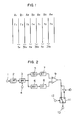
- Fig. 1 shows magnetic recording traces of the pilot signals. In the figure, Ai, 81, A2, and so on are magnetized traces produced by head A and head B, and each recording track has a record of video signal of one-field length. The pilot signals indicated by f1 through f4 are recorded over the video signal and arranged orderly for each field. The pilot signals have frequencies as listed in Table 1, in which fH denotes the frequency of the horizontal sync signal.
-

- Pilot signals of adjacent tracks have a difference of frequencies of fH or 3fH as shown in Fig. 1. Accordingly, by extracting each frequency difference and comparing the levels, a tracking error signal related to the tracking deviation can be obtained.
- Fig. 2 is a block diagram of the circuit for producing the tracking error signal. In the figure, a
terminal 1 receives the reproduced RF signal, and a low-pass filter 2 extracts only pilot signals. A balanced modulation (BM)circuit 3 produces the difference of frequencies of the pilot signal received and a reference signal received atterminal 4. For example, the pilot signal reproduced when the head scans the track A2 in Fig. 1 includes f3 which is reproduced on the main scanning track and a composite signal of f2 and f4 which is reproduced as a crosstalk signal. The reference signal at this time is the pilot signal f3 recorded on the main scanning track. TheBM circuit 3 at this time provides outputs having frequency differences between f3 and each of f2, f3 and f4, and they include signals of fH and 3fH. These differential frequency signals are picked up by atuning circuit 5 which extracts fH and atuning circuit 6 which extracts 3fH, and fed through detectingcircuits comparison circuit 9, which is followed by an analog invertingcircuit 10 and an electronic analog switch 11. The switch 11 operates in response to the head switching signal received at aterminal 12, and the output of thecomparison circuit 9 and its inverted version are outputted at aterminal 13 alternately for every field. The reason for the need of signal inversion is that the extracted tracking signal has opposite polarities for head A and head B. Namely, a deviation of head A to the right causes an increase in the fH component, while that of head B causes a decrease in the fH component. In consequence, the tracking error signal whose polarity is independent of the playback heads can be obtained at theterminal 13. - In order for the tracking control system based on the foregoing principle to accomplish variable-speed playback without producing a noise on the screen, the following requirements must be fulfilled.
- (1) The scanning start point of the head must be located virtually at the center of the intended track.
- (2) The angle of the head scanning trace must coincide with the angle of the recording track.
- (3) The pilot signal recorded on the main scanning track must be selected for use as the reference signal supplied to the BM circuit.
- In the normal-speed playback operation in which the tape speed is the same as recording, the reference signal supplied to the BM circuit is switched for each field in the order of f1→f2→f3→f4→f1. The reason is that the pilot signal reproduced on the recording track also has the order of f1→f2→f3→f4, and even if it is not coincident with the reference signal initially, the resultant tracking error signal acts to control the phase of tape control so that tracking control will settle at the time point when both signals coincide with each other.
- When a record is played at a tape speed different from the recording tape speed, the order of switching the reference signal varies depending on the playback tape speed. For example, in the double-speed playback mode, the reference signal is switched in the order of f1→f3→f1→f3, while in the triple-speed playback mode, the order is f1→f4→f3→f2→f1.
- When the variable-speed playback mode includes a small number of tape speeds only, e.g., only forward triple-speed playback, or only sevenfold-speed forward and fivefold-speed backward playback as is the case in the before-referenced known recording-playback apparatus, the system may be designed such that the order of reference signal switching in that mode is preset in a memory circuit and the reference signal is produced in accordance with the command retrieved from the memory circuit. This method may be effective for the case of a fast playback mode having a limited number of tape speeds, however, it is not convenient for the case of many playback speeds because of a great capacity needed for the memory circuit for storing the order of reference signal switching in correspondence to all tape speeds. Moreover, the known recording-playback apparatus does not allow for selecting playback speeds which are a non-integer multiple of the recording speed.
- Another problem is that when one playback speed is changed to another speed, the tape feed might not follow a changed reference signal satisfactorily. If the new playback tape speed is greatly different from the current tape speed, the tape feed cannot follow the command for a significant time length, resulting in the creation of a noise in the reproduced picture. This improperty may be avoided through the arrangement of sensing the tape speed at every moment and generating the piezo-electric element application voltage accordingly, however it needs a complex processing. Alternatively, the tape feed response performance is examined in advance and the piezo-electric element application voltage is generated to suit the performance, however, this method also needs a complex processing and the tape feed response may possibly change due to a change in the load of tape feed mechanism caused by an environmental change, aging of the mechanism, or the like.
- For a playback system operable for continuous variable-speed playback, a d.c. component included in the voltages applied to the piezo-electric element or voice coil forming the electromechanical transducer for mounting the head often adversely affects the life and performance of the devices and deteriorates the power efficiency of the whole system including the driving stage. Therefore, application of a d.c. component to the system component devices must be avoided thoroughly.
- In order to avoid the application of a DC component to the electromechanical transducer carrying the rotary magnetic heads, another known recording-playback apparatus (EP-A-79 748) comprises a phase- locked loop in which a control signal recorded along one of the edges of the magnetic tape and comprising one pulse for each recorded frame is sensed during playback, and the sensed control pulses are divided by an integer number representing the ratio of the current playback speed as compared to the recording speed to thereby control the position of the magnetic tape with respect to the rotary magnetic heads. This phase- locked control loop comprises a delay circuit for the control pulses, which delay circuit is controlled by the average voltage value formed from the preset voltage waveform which is necessary for driving the electromechanical transducer of the recording-playback apparatus to cause the rotary magnetic heads mounted thereon to follow the recording tracks. Thereby the positional relation between the magnetic tape and the scan tracks of the magnetic heads is controlled during playback in such a way that the average value of the preset voltage waveform applied to the electromechanical transducer is zero, i.e. that no DC component is applied to the transducer. Again, this known recording-playback apparatus is not capable of selecting a playback speed which is a non-integer multiple of the recording speed.
- It is thus an object of the present invention to provide for a magnetic recording playback apparatus of the above-referenced type which is adapted to allow for tape feed speeds during playback which include non-integer multiples of the recording speed.
- This object is attained in accordance with the invention in that a center value Vn+i and slope SLn+1 defining the preset voltage waveform and a signal REn+i indicative of the respective pilot signal for a next head scanning are calculated from the corresponding values of the previous head scanning through an arithmetic process according to


- By the invention a continuous variable-speed playback operation for a magnetic recording-playback apparatus orvideo tape recorder (VTR) is therefore accomplished which implements the tracking control by processing signals obtained through the playback head only.
- The various terms in the above expressions (1) to (3) are expressed in the form of quotients and are thereby normalized in units of the track pitch Tp.
- For example, a V"/V, equal to one signifies the voltage necessary for the head deviation by a length of one Tp, with its positive polarity indicating the same tape feed direction as recording, while a Vn/Vt equal to -1 signifies the voltage forthe head deviation by one Tp in the direction opposite to the recording tape feed direction. Expression (1) includes a constant K, which is an integer determined so that the inequality appearing on the right side of (1) is satisfied. The tape speed is also treated in terms of Tp, taking TS"/TSt=1 for the normal-speed playback, TS"/TSt=2 for the double-speed playback, and TSn/TSt=-1 for the reverse standard-speed playback. The voltage slope is also treated identically, taking SLn+1/SLt=1 (double-speed playback) for an amount of slope of one Tp, or SLn+1/SLt=-1 (still picture reproduction) for an amount of opposite slope of one Tp. The kind of reference signal REn, where REn=i, corresponds to a pilot signal of fi, where i is an integer ranging from 1 through 4. Constant K used in expression (3) is given the value determined for expression (1), and the other constnat m is an integer which is determined so that the inequalities appearing on the right side of (3) are satisfied.
- Fig. 1 is a diagram showing the magnetic recording trace of the record of the pilot signals; Fig. 2 is a block diagram showing the reproduction circuit for obtaining the tracking error signal; Fig. 3 is a diagram showing the head scanning traces in the forward and reverse triple-speed playback modes; Fig. 4 is a block diagram showing in brief the system arrangement for implementing noise-free variable-speed playback; Fig. 5 is a waveform diagram showing the preset voltage and reference signal in the forward triple-speed playback mode; Fig. 6 is a waveform diagram showing the preset voltage and reference signal in the reverse triple-speed playback mode; Fig. 7 is a block diagram showing an embodiment of this invention; Fig. 8 is a block diagram showing in more detail the error signal processing circuit for piezo-electric element used in this embodiment; Fig. 9 is a flowchart showing the processing implemented by the arithmetic processing circuit; Fig. 10 is a flowchart showing the processing of the subroutine used in Fig. 9; Fig. 11 is a set of flowcharts showing the modification process; Fig. 12 is a flowchart for the arithmetic processing circuit for implementing additionally the process for reducing a d.c. component; Fig. 13 is a flowchart for a d.c. component reducing process; Fig. 14 is a diagram showing a reduction in the d.c. component; and Fig. 15 is a diagram showing a remaining d.c. component.
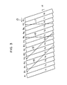
- Fig. 3 shows magnetic traces of pilot signals f1, f2, f3 and f4 recorded on the magnetic tape. The head scans the tape in the direction shown by the
arrow 14, while the tape is fed in the direction shown by thearrow 15. Traces A,, B1, A2, B2, and so on are recorded by head A andhead B. Lines 16 and 17 indicate the head scanning traces produced when the tape is fed at a speed three times the recording tape speed in the triple-speed playback mode.Lines - For the accomplishment of noise-free variable-speed playback, it is necessary for the head to scan one of tracks, and for this purpose the head needs to deviate in the traversing direction of the recording track. It is a general convention to achieve the head deviation by mounting it on an electromechanical transducer such as a piezo-electric element.
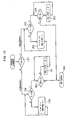
- Fig. 4 is a block diagram for implementing the noise-free special playback operation without using any control signal. In the figure, a magnetic tape 27 is transported by means of a
capstan 28 and a pinch roller (not shown).Reference number 29 denotes a capstan motor, and 30 and 31 in combination constitute a frequency generator (FG) for measuring the number of rotation of thecapstan 28. Thecapstan motor 29 is driven by adrive circuit 33 under control of aspeed control circuit 32 so that the output frequency of the FG is always constant. Thecapstan motor 29 runs at an rpm in compliance with the speed command signal issued by aspeed command circuit 34.Reference number 35 denotes a magnetic head placed on a piezo-electric element 36, and both members are rotated by being mounted on a rotary cylinder (not shown). Various signals reproduced through themagnetic head 35 are delivered to asignal processing circuit 37, and the reproduced video signal is outputted through itsterminal 38. The pilot signal recorded over the video signal is extracted by thesignal processing circuit 37 and supplied to a trackingerror evaluation circuit 39. Thecircuit 39 is located across the main scanning track and designed to produce a tracking error signal proportional to the difference of the crosstalk signals reproduced on both adjacent tracks. The operation of thecircuit 39 is the same as described previously in connection with Fig. 2. - The tracking error signal is supplied to the capstan
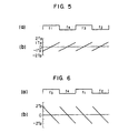
speed control circuit 32 and used to control the phase of tape feed. A presetwaveform generating circuit 41 produces a preset waveform in response to the speed command signal, and in practice signals can be processed by use of a microprocessor and its associated devices. A trackingerror processing circuit 40 receives the tracking error signal from thecircuit 39 and extracts a tracking error signal only for the amount of a track curve, for example. The output of the trackingerror processing circuit 40 and the preset waveform provided by thecircuit 41 are merged, and the resultant signal operates on thedrive circuit 42 to drive the piezo-electric element 36. - Fig. 5 shows the preset voltage waveform supplied to the electromechanical transducer in the forward triple-speed playback mode. The waveform shown in (a) is the head switching signal, which carries reference signals f1, f4, f3 and f2 used for the respective fields. The sawtooth wave shown in (b) is the voltage waveform applied to the electromechanical transducer, and the voltage is plotted vertically in terms of the track pitch (Tp) with the polarity being positive for the tape feed direction shown by 15 in Fig. 3 and negative for the opposite tape feed direction. With the voltage of Fig. 5(b) supplied to the electromechanical transducer, the head scans track A5 in Fig. 3 for the first field and it scans track B6 for the next field.
- Fig. 6 shows the reference signals used in the reverse triple-speed playback mode and the voltage waveform applied to the electromechanical transducer.
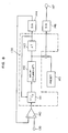
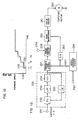
- Fig. 7 shows in more detail the processing circuit for the piezo-electric element shown in Fig. 4. The tracking error signal produced by the
circuit section 127 enclosed in the dashed block, which has been described in connection with Fig. 2, is received by acomparison circuit 129 and compared with the error signal of the previous frame received at the negative input terminal of the circuit. Thecomparison circuit 129 delivers its output to an errorsignal processing circuit 131 used for the piezo-electric element. Details of thecircuits circuit 131 provides a d.c. component of track deviation and a tracking error signal corresponding to a track curve. A presetwaveform generating circuit 132 produces the sawtooth wave as shown in Fig. 5, for example. The preset voltage varies depending on the playback tape speed, and its details will be described later. The tracking error signal and preset signal for the piezo-electric element are added, and processed by a D/A converter 135 and adrive circuit 136 for the electromechanical transducer, and then applied to theelectromechanical transducer 120 so that thehead 121 scans the main scanning track for the picture reproduction. - Next, a particular arrangement of the
circuit 131 will be described. Fig. 8 shows the block diagram related to thecircuit 131, where thecircuit section 138 enclosed by the dashed line corresponds to thecircuit 131.Circuit 140 is a level comparison circuit which is identical to thecomparison circuit 129 shown in Fig. 7. The tracking error signal received at a terminal 139 is compared for the level with the tracking error signal of the preceding frame. Acircuit 141 performs fine modification for the tracking error signal of the preceding frame by addition of one or subtraction of one depending on the output of thecircuit 140. The modified error signal is delayed bydelay circuits fine modification circuit 141. Thecircuit 143 is a delay circuit used to compensate the delay of control circuit after the signal with a delay of one frame time length minus AT has been outputted from thecircuit 142 until it is obtained as a tracking error signal at the terminal 139. The output of thecircuit 143 is processed by the D/A converter 144 and supplied to thecomparison circuit 140. The output of thecircuit 142 is added to the output of the presetwaveform generating circuit 145, processed by a D/A converter 146, and outputted through a terminal 147. A particular arrangement of the errorsignal processing circuit 131 for the piezo-electric element has been described. - Next, the processing for the variable-speed playback mode will be described. The arrangement of Fig. 7 includes a tape
speed command circuit 133, which processes a signal entered through a key 138, for example, and produces a tape speed command signal. The command signal is supplied to acapstan control circuit 128 so that the tape feed speed is determined. Signals entered to anarithmetic processing circuit 134 include the tape speed command signal, preset voltage center value and current reference signal stored in the arithmetic processing circuit. The center value signifies the level of the preset voltage waveform at the middle of its slope, and it is zero Tp in Figs. 5 and 6, for example. Output signals resulting from the processing of these input signals include a value of slope of the preset waveform and a command signal for determining the reference signal necessary for the subsequent scanning operation. The 2-bit command signal operates on the referencesignal generating circuit 137 to produce one of f, through f4. - Next, the processing of the
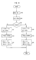
arithmetic processing circuit 134 will be described. In the following discussion, four kinds of reference signals are generally termed as "reference signal". - Figs. 9 and 10 are flowcharts showing the procedures of processing. Fig. 9 shows the procedure of obtaining the preset waveform for the next (n+1)th field from the known preset waveform for the (n)th field, with the assumption that the track is scanned by head B for the (n)th field. Symbols Vm and REm are the center value of the preset voltage waveform and a signal indicative of a respective one of signals f1 through f4, respective capitals A and B preceding Vm and REm indicate association with head A or B, respectively. It is also assumed that the center value BVn of the preset waveform and the reference signal BREn are known. Accordingly, the subject is to obtain the value of AVn+i and AREn+i for the next field.
- Initially, the current tape speed TSn is read in the
speed command circuit 133, for example, inblock 148. Subsequently, the slope SLn+1 of the preset waveform is calculated using equation SLn+i=TSn-1 as shown instep 149. These variables are treated in units of track pitch. For example, TSn=1 (one track pitch) in the normal-speed playback mode and therefore slope SLn+1 is zero, while SLn+1 becomes two in the triple-speed playback mode, and it takes -4 for the reverse triple-speed playback mode. The tape speed TSn is not limited to an integer, but it can take an arbitrary real number. The preset waveform of the next field, i.e., (n+1)th field, has a center voltage AVn+1 which is supposed to be the center voltage BVn of the (n)th field added by the tape speed TSn. Namely, the (n+1)thfield will be reproduced by the scanning of head A, and a temporary value V=BVn+TSn is obtained throughstep 150. At the same time, a temporary reference signal RE=BREn is also set. If the same reference signal is used repeatedly for several fields, the value of V will increase progressively, and to avoid this the reference signal is varied instep 152 so that the V takes a value within ±0.5 track pitch. This is the reason for the above phrasing "temporary". - From the values V and RE (RE=1 for f1, RE=2 forf2, RE=3 for f3 and RE=4 for f4) processed as described above, the center value AVn+1 and reference signal AREn+1 for the next (n+1 )th field are obtained and the slope ASLn+1 of the (n+1)th field is obtained from the slope SLn+1 in
step 153. These are the procedure for obtaining the center value AVn+1and reference signal AREn+1 for the (n+1)th field (scanned by head A) from the center value BV" and reference signal BREn forthe (n)th field (scanned by head B). Next, the operation of the case when head A is used for scanning for the (n)th field will be described. In this case, the (n+1 )th field is reproduced by the scanning of head B as determined instep 150, and and therefore AVn+TSn is entered to the temporary center value V and AREn is entered to the temporary reference signal RE instep 154, and the reference signal is changed by the process of step 155 (same process as step 152) so that the V takes a value within ±0.5 track pitch. From the values V and RE processes as described above, the center value BVn+1 and reference signal BREn+1 for the next field ((n+1)th field scanned by head B) are obtained. Discrimination of scanning by head A or head B can be based on the value of the head switching signal, or it is also possible to know the scanning head basing on as to whether the value of n is odd or even. (The correspondence rule for the head discrimination is determined at the beginning). These are the procedure for obtaining the values (center value, slope and reference signal) for the (n+1)th field from the values for the (n)th field. This procedure is executed for each field. - Next, the "track change" process which takes place in
steps Steps Steps values 1 through 4 of RE, the value of RE in excess of 4 is subtracted by 4 so that it takes one of 1 through 4. The processing for the reverse playback mode takes place in the same principle, and the values V and RE are modified. These are the explanation for thearithmetic processing circuit 134 shown in Fig. 7. In Fig. 7, the circuit section enclosed in the dashedblock 130 can entirely operate using digital signals, and the signals can be processed using a microprocessor. - Although a 2-head helical scanning VTR has been described as an example, the present invention can also be applied to VTRs using four kind of pilot signals, e.g., 1-head VTRs and 4-head VTRs with smaller cylindr diameter.
- The foregoing procedures for selecting a scanning track in the playback operation are inconvenient for some recording system of VTR. This type of VTR operates to record at different azimuthes for head A and head B so that crosstalk of luminous signal component from adjacent tracks decreases for the purpose of high density recording. In this case, scanning by head B on the track which has been recorded by head A does not provide a sufficient reproduction output, and vice versa. Therefore, it is necessary for both heads to scan the recording tracks which have been recorded at the same azimuth. Namely, the results of processings described using Figs. 9 and 10 need to be modified such that head A scans a track with reference signal f1 or f3, while head B scans a track with reference signal f2 or f4. This processing procedure shown in the flowchart of Fig. 11 will be described in the following. In Fig. 11(a), step 167 tests as to whether the track scanned by head A has an odd reference signal (1 or 3). If the reference signal is odd, the sequence branches to step 171. If it is even (2 or 4), the sequence proceeds to step 168 to read the center value AVn+1 of the application voltage at the scanning of head A, and it is modified by one track pitch so that the absolute value does not exceed one track pitch. (Namely, if AVn+1 is positive, it is subtracted by one track pitch). At the same time, the reference signal is also modified by one. These operations are carried out in
steps - Next, the modification method for the scanning by head B will be described. There are two ways for the arrangement of head B. One is the provision of the same azimuth as head A, and the other is the provision of the same azimuth as recording. The former will be termed "field reproduction" and the latter "frame reproduction". In field reproduction, head B scans a track with an odd reference signal, while in frame reproduction, head B scans a track with an even reference signal. In Fig. 11(b),
step 172 selects field reproduction or frame reproduction. For field reproduction, the sequence proceeds to step 173 to test whether the reference signal BREn+1 at the scanning by head B is odd. If it is odd, the values are used without modification instep 175. If it is even, the sequence proceeds to step 176 to modify BVn+1 and BREn+1 (steps 177 and 178). These are the case of field reproduction. - For frame reproduction, step 174 tests whether the reference signal BREn+i is even. Unless the signal is even, the sequence proceeds to step 176 to modify BVn+1 and BVn+1 and BREn+1' Using the modified values BV'n+1 and BRE'n+1 the actual tracking control takes place. It should be noted that the values BVn+1 and BREn+1 before the modifying operation are used to obtain the values for the next field. These modification processes are executed after the values for the next field have been obtained in Fig. 9.
- The following describes the method of preventing the application of a d.c. component to the piezo-electric element in the foregoing method.
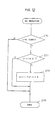
- The Vn+1 (the center value of the piezo-eiectric element application voltage, i.e., a d.c. component) which is obtained by the process described above may possibly retain a d.c. component smaller than 1/2 track pitch. In Fig. 15, heads H1, H2, and so on without voltage application are out of the center of tracks A,, B1, A2, B2, and so on, and there arises a case in which the heads scan the track center by application of voltages Vn, Vn+1, and so on. This case arises when TS=1 and, at the same time, Vn#0, for example. On this account, after the application voltage Vn+1 has been obtained, process "d.c. reduction" 267 is added as shown in Fig. 12. The processing is shown in Fig. 13.
- In Fig. 13, step 270 tests whether this is the j-th entry to the routine. If it is true, the sequence proceeds to step 271, or if not, the sequence branches to step 274 to terminate the process. The variable j is an integer larger than zero. Subsequently, step 271 tests whether the AVn+1 or BVn+1 (only Vn+1 is shown here) obtained through the processes of Figs. 9 to 11 is zero. If Vn+1 has a value of zero, the sequence proceeds to step 274 to terminate the process, or if not, the sequence proceeds to step 273, in which the Vn+1 obtained through the processes of Figs. 9 to 11 is updated by being added by 6. Then the process completes.
- By addition of the process shown in Fig. 13, the value of Vn+1 becomes zero in a finite time. This process, as a result, performs modulation of tape feed, thereby matching the head position to the phase of tape feed. Assuming a head Hn to scan track n in Fig. 14, the head center deviates from the track center by the value corresponding to Vn. On this account, the voltage Vn is applied so that the head is displaced by the amount of Vn. The same process takes place for the combination of track n+1 and head Hn+1' The voltage Vn+1 corresponds to the displacement of the head Hn+1. The process of Fig. 13 is the case of head displacement by Vn+1+δ instead of Vn+1. The head position after the voltage application is displaced by 6 from the track center as shown by H'n+1. Accordingly, the tracking error signal obtained at this time is offset by the amount corresponding to δ. The tracking error signal is fed to the capstan control circuit as shown in Fig. 7 for use in tape feed control, and the tape feed speed varies by the amount corresponding to 6, and it is controlled so that the head scanning center finally coincides with the track center. The value of 6 is so small that the signal level does not fall significantly due to the tracking deviation by the amount of before the tape feed control system settles, and no problem will arise. The polarity of 6 may be selected so that the value of Vn+1 approaches zero following the modification. This scheme favorably halves the maximum value of time spent in the zero-approach as compared with the case of a fixed polarity.
- This invention enables VTRs without using signals on the control track to reproduce picture at variable playback speed with extremely little occurrence of noises on the screen. Particularly, its almost step-less tape speed change allows the full exertion of the features of the moving head supported by the piezo-electric element. The inventive system is immediately applicable not only to the currently prevailing 2-head helical scanning system, but also to various other magnetic tape recording systems including the 4-head system and azimuth recording system, and it is greatly valuable for the industry.
Claims (4)


Applications Claiming Priority (6)
| Application Number | Priority Date | Filing Date | Title |
|---|---|---|---|
| JP95001/84 | 1984-05-11 | ||
| JP59095001A JPS60237777A (en) | 1984-05-11 | 1984-05-11 | Magnetic video recording and reproducing device |
| JP147801/84 | 1984-07-17 | ||
| JP14780184A JPS6126378A (en) | 1984-07-17 | 1984-07-17 | Magnetic recording and reproducing device |
| JP59197106A JPS6174128A (en) | 1984-09-20 | 1984-09-20 | Magnetic recording and reproducing device |
| JP197106/84 | 1984-09-20 |
Publications (3)
| Publication Number | Publication Date |
|---|---|
| EP0181942A1 EP0181942A1 (en) | 1986-05-28 |
| EP0181942A4 EP0181942A4 (en) | 1988-11-29 |
| EP0181942B1 true EP0181942B1 (en) | 1991-01-16 |
Family
ID=27307715
Family Applications (1)
| Application Number | Title | Priority Date | Filing Date |
|---|---|---|---|
| EP85902162A Expired - Lifetime EP0181942B1 (en) | 1984-05-11 | 1985-05-09 | Magnetic recording/reproducing apparatus |
Country Status (5)
| Country | Link |
|---|---|
| US (1) | US4791507A (en) |
| EP (1) | EP0181942B1 (en) |
| KR (1) | KR900000127B1 (en) |
| DE (1) | DE3581372D1 (en) |
| WO (1) | WO1985005522A1 (en) |
Families Citing this family (13)
| Publication number | Priority date | Publication date | Assignee | Title |
|---|---|---|---|---|
| US4764819A (en) * | 1985-07-18 | 1988-08-16 | Matsushita Electric Industrial Co., Ltd. | Method and apparatus for helical scan type magnetic recording and reproducing with a rotary magnetic head |
| KR910006487B1 (en) * | 1986-06-26 | 1991-08-26 | 미쓰비시덴기 가부시기가이샤 | Picture image play back apparatus |
| DE3769028D1 (en) * | 1986-07-22 | 1991-05-08 | Matsushita Electric Ind Co Ltd | DEVICE FOR PLAYING BACK SIGNALS RECORDED ON A TAPE. |
| US5214515A (en) * | 1986-10-28 | 1993-05-25 | Mitsubishi Denki Kabushiki Kaisha | Video signal recording/reproducing apparatus |
| US5210663A (en) * | 1989-04-10 | 1993-05-11 | Matsushita Electric Industrial Co., Ltd. | Tracking control device and magnetic recording and reproducing apparatus using the device |
| US5255140A (en) * | 1989-12-29 | 1993-10-19 | Samsung Electronics Co., Ltd. | VCR magnetic recording head for both digital and VHS format |
| KR920006303B1 (en) * | 1990-05-21 | 1992-08-03 | 삼성전자 주식회사 | Auto track locking condition checking circuit |
| JP2776005B2 (en) * | 1990-07-06 | 1998-07-16 | ソニー株式会社 | Digital signal recording / reproducing device |
| JP2808176B2 (en) * | 1990-08-27 | 1998-10-08 | キヤノン株式会社 | Video tape recorder shuttle and variable device |
| KR0155737B1 (en) * | 1992-12-23 | 1998-12-15 | 김광호 | Tracking control method and device for vcr |
| JP3579926B2 (en) * | 1994-08-25 | 2004-10-20 | ソニー株式会社 | Digital video signal reproducing method and reproducing apparatus |
| JP2001229516A (en) * | 2000-02-10 | 2001-08-24 | Sony Corp | Recording/reproducing device and recording/reproducing method |
| JP3538585B2 (en) * | 2000-04-13 | 2004-06-14 | オリオン電機株式会社 | Tape drive |
Family Cites Families (24)
| Publication number | Priority date | Publication date | Assignee | Title |
|---|---|---|---|---|
| JPS6030009B2 (en) * | 1976-12-02 | 1985-07-13 | ソニー株式会社 | automatic tracking device |
| JPS5456119A (en) * | 1977-10-11 | 1979-05-04 | Sony Corp | Speed controller for motor |
| JPS5497007A (en) * | 1978-01-17 | 1979-07-31 | Sony Corp | Head supporting structure |
| JPS5538649A (en) * | 1978-09-07 | 1980-03-18 | Sony Corp | Tracking unit of magnetic head |
| JPS5539478A (en) * | 1978-09-14 | 1980-03-19 | Sony Corp | Regenerator of video signal |
| US4296446A (en) * | 1979-11-15 | 1981-10-20 | Rca Corporation | Motor speed control circuit |
| US4521815A (en) * | 1981-07-10 | 1985-06-04 | Victor Company Of Japan, Limited | Reproducing apparatus capable of performing high-speed reproduction of a video signal |
| US4481544A (en) * | 1981-09-18 | 1984-11-06 | Ampex Corporation | Automatic tracking system with apparatus to prevent mistracking by a limited range transducer during stop motion |
| JPS5873045A (en) * | 1981-10-27 | 1983-05-02 | Matsushita Electric Ind Co Ltd | Capstan servo circuit |
| JPS5880980A (en) * | 1981-11-09 | 1983-05-16 | Matsushita Electric Ind Co Ltd | Tracking device |
| DE3147596C2 (en) * | 1981-12-02 | 1985-01-17 | Loewe Opta Gmbh, 8640 Kronach | Procedure for automatic scanning track setting in video magnetic tape recorders with helical track recording |
| JPS58194480A (en) * | 1982-05-07 | 1983-11-12 | Matsushita Electric Ind Co Ltd | Magnetic video recording and reproducing device |
| JPS58212646A (en) * | 1982-06-04 | 1983-12-10 | Hitachi Ltd | Reproducing device of variable speed of magnetic recording and reproducing device |
| JPS5924465A (en) * | 1982-07-30 | 1984-02-08 | Hitachi Ltd | Controller of variable speed reproduction of magnetic video recording and reproducing device |
| JPS5934775A (en) * | 1982-08-23 | 1984-02-25 | Matsushita Electric Ind Co Ltd | Rotary head type magnetic video recording and reproducing device |
| JPS5940784A (en) * | 1982-08-31 | 1984-03-06 | Sony Corp | Still picture reproducer |
| JPS5948819A (en) * | 1982-09-13 | 1984-03-21 | Matsushita Electric Ind Co Ltd | Tracking device |
| JPH0644368B2 (en) * | 1982-12-24 | 1994-06-08 | 株式会社日立製作所 | VTR variable speed playback device |
| JPS59195364A (en) * | 1983-04-20 | 1984-11-06 | Canon Inc | Video signal reproducer |
| JPS59127223A (en) * | 1983-01-11 | 1984-07-23 | Canon Inc | Video signal reproducing device |
| JPH0754571B2 (en) * | 1983-02-02 | 1995-06-07 | キヤノン株式会社 | Video signal playback device |
| JPS59185058A (en) * | 1983-04-01 | 1984-10-20 | Hitachi Ltd | Magnetic recording and reproducing device |
| JPS59229735A (en) * | 1983-06-10 | 1984-12-24 | Canon Inc | Automatic tracking device |
| AT378301B (en) * | 1983-06-17 | 1985-07-25 | Philips Nv | SYSTEM FOR PLAYING BACK SIGNALS STORED ON A MAGNETIC TAPE |
-
1985
- 1985-05-09 EP EP85902162A patent/EP0181942B1/en not_active Expired - Lifetime
- 1985-05-09 DE DE8585902162T patent/DE3581372D1/en not_active Expired - Lifetime
- 1985-05-09 WO PCT/JP1985/000259 patent/WO1985005522A1/en active IP Right Grant
- 1985-05-09 KR KR1019860700015A patent/KR900000127B1/en not_active IP Right Cessation
- 1985-05-09 US US06/817,860 patent/US4791507A/en not_active Expired - Lifetime
Also Published As
| Publication number | Publication date |
|---|---|
| US4791507A (en) | 1988-12-13 |
| WO1985005522A1 (en) | 1985-12-05 |
| KR860700200A (en) | 1986-03-31 |
| DE3581372D1 (en) | 1991-02-21 |
| EP0181942A1 (en) | 1986-05-28 |
| KR900000127B1 (en) | 1990-01-20 |
| EP0181942A4 (en) | 1988-11-29 |
Similar Documents
| Publication | Publication Date | Title |
|---|---|---|
| EP0421417B1 (en) | Magnetic recording and reproducing apparatus | |
| EP0181942B1 (en) | Magnetic recording/reproducing apparatus | |
| EP0094194B1 (en) | Magnetic recording and reproduction system | |
| EP0032834B1 (en) | A positionable element driving circuit | |
| EP0089816A2 (en) | Apparatus for controlling the tracking position of a head in an apparatus for recording or reproducing information | |
| KR930001151B1 (en) | Magnetic recording/reproducing apparatus | |
| EP0302696B1 (en) | Tracking control for magnetic recording and/or reproducing apparatus | |
| US4393416A (en) | Tracking system for a videotape recorder | |
| EP0194445B1 (en) | Auto tracking apparatus for video tape recorder | |
| US4489352A (en) | Video tape recording/reproducing apparatus having an auto tracking function | |
| US3869708A (en) | Speech compressor with gap filling | |
| US4393417A (en) | Tracking system | |
| KR0137333B1 (en) | Tracking control method and the apparatus at the time of double-speed reproducing | |
| EP0171714A1 (en) | Recording and reproducing apparatus | |
| JPH0377571B2 (en) | ||
| US5793925A (en) | Recording method and apparatus for control track | |
| JP2597968B2 (en) | Rotating head type video signal reproducing device | |
| JPH0313789B2 (en) | ||
| JP2574526B2 (en) | Magnetic recording / reproducing device | |
| KR0183170B1 (en) | Reproducing method for the slow-motion picture of digital vcr | |
| JPS6123579B2 (en) | ||
| JPH0542731B2 (en) | ||
| JPS62243112A (en) | Tracking control device | |
| JPH0670846B2 (en) | Rotating head type video signal reproducing device | |
| JPH0666084B2 (en) | Rotating head type video signal reproducing device |
Legal Events
| Date | Code | Title | Description |
|---|---|---|---|
| PUAI | Public reference made under article 153(3) epc to a published international application that has entered the european phase |
Free format text: ORIGINAL CODE: 0009012 |
|
| 17P | Request for examination filed |
Effective date: 19860108 |
|
| AK | Designated contracting states |
Kind code of ref document: A1 Designated state(s): DE FR GB |
|
| RAP1 | Party data changed (applicant data changed or rights of an application transferred) |
Owner name: MATSUSHITA ELECTRIC INDUSTRIAL CO., LTD. |
|
| A4 | Supplementary search report drawn up and despatched |
Effective date: 19881129 |
|
| 17Q | First examination report despatched |
Effective date: 19890517 |
|
| GRAA | (expected) grant |
Free format text: ORIGINAL CODE: 0009210 |
|
| AK | Designated contracting states |
Kind code of ref document: B1 Designated state(s): DE FR GB |
|
| REF | Corresponds to: |
Ref document number: 3581372 Country of ref document: DE Date of ref document: 19910221 |
|
| ET | Fr: translation filed | ||
| PLBE | No opposition filed within time limit |
Free format text: ORIGINAL CODE: 0009261 |
|
| STAA | Information on the status of an ep patent application or granted ep patent |
Free format text: STATUS: NO OPPOSITION FILED WITHIN TIME LIMIT |
|
| 26N | No opposition filed | ||
| PGFP | Annual fee paid to national office [announced via postgrant information from national office to epo] |
Ref country code: GB Payment date: 19960430 Year of fee payment: 12 |
|
| PGFP | Annual fee paid to national office [announced via postgrant information from national office to epo] |
Ref country code: FR Payment date: 19960510 Year of fee payment: 12 |
|
| PGFP | Annual fee paid to national office [announced via postgrant information from national office to epo] |
Ref country code: DE Payment date: 19960513 Year of fee payment: 12 |
|
| PG25 | Lapsed in a contracting state [announced via postgrant information from national office to epo] |
Ref country code: GB Effective date: 19970509 |
|
| GBPC | Gb: european patent ceased through non-payment of renewal fee |
Effective date: 19970509 |
|
| PG25 | Lapsed in a contracting state [announced via postgrant information from national office to epo] |
Ref country code: FR Free format text: LAPSE BECAUSE OF NON-PAYMENT OF DUE FEES Effective date: 19980130 |
|
| PG25 | Lapsed in a contracting state [announced via postgrant information from national office to epo] |
Ref country code: DE Free format text: LAPSE BECAUSE OF NON-PAYMENT OF DUE FEES Effective date: 19980203 |
|
| REG | Reference to a national code |
Ref country code: FR Ref legal event code: ST |