EP0181230B1 - Improvements in or relating to building blocks - Google Patents
Improvements in or relating to building blocks Download PDFInfo
- Publication number
- EP0181230B1 EP0181230B1 EP85308134A EP85308134A EP0181230B1 EP 0181230 B1 EP0181230 B1 EP 0181230B1 EP 85308134 A EP85308134 A EP 85308134A EP 85308134 A EP85308134 A EP 85308134A EP 0181230 B1 EP0181230 B1 EP 0181230B1
- Authority
- EP
- European Patent Office
- Prior art keywords
- blocks
- block
- bearing surface
- course
- front face
- Prior art date
- Legal status (The legal status is an assumption and is not a legal conclusion. Google has not performed a legal analysis and makes no representation as to the accuracy of the status listed.)
- Expired - Lifetime
Links
Images


Classifications
-
- E—FIXED CONSTRUCTIONS
- E04—BUILDING
- E04B—GENERAL BUILDING CONSTRUCTIONS; WALLS, e.g. PARTITIONS; ROOFS; FLOORS; CEILINGS; INSULATION OR OTHER PROTECTION OF BUILDINGS
- E04B2/00—Walls, e.g. partitions, for buildings; Wall construction with regard to insulation; Connections specially adapted to walls
- E04B2/02—Walls, e.g. partitions, for buildings; Wall construction with regard to insulation; Connections specially adapted to walls built-up from layers of building elements
- E04B2/04—Walls having neither cavities between, nor in, the solid elements
- E04B2/12—Walls having neither cavities between, nor in, the solid elements using elements having a general shape differing from that of a parallelepiped
-
- E—FIXED CONSTRUCTIONS
- E02—HYDRAULIC ENGINEERING; FOUNDATIONS; SOIL SHIFTING
- E02D—FOUNDATIONS; EXCAVATIONS; EMBANKMENTS; UNDERGROUND OR UNDERWATER STRUCTURES
- E02D29/00—Independent underground or underwater structures; Retaining walls
- E02D29/02—Retaining or protecting walls
- E02D29/025—Retaining or protecting walls made up of similar modular elements stacked without mortar
-
- E—FIXED CONSTRUCTIONS
- E04—BUILDING
- E04C—STRUCTURAL ELEMENTS; BUILDING MATERIALS
- E04C1/00—Building elements of block or other shape for the construction of parts of buildings
- E04C1/39—Building elements of block or other shape for the construction of parts of buildings characterised by special adaptations, e.g. serving for locating conduits, for forming soffits, cornices, or shelves, for fixing wall-plates or door-frames, for claustra
- E04C1/395—Building elements of block or other shape for the construction of parts of buildings characterised by special adaptations, e.g. serving for locating conduits, for forming soffits, cornices, or shelves, for fixing wall-plates or door-frames, for claustra for claustra, fences, planting walls, e.g. sound-absorbing
-
- E—FIXED CONSTRUCTIONS
- E04—BUILDING
- E04B—GENERAL BUILDING CONSTRUCTIONS; WALLS, e.g. PARTITIONS; ROOFS; FLOORS; CEILINGS; INSULATION OR OTHER PROTECTION OF BUILDINGS
- E04B2/00—Walls, e.g. partitions, for buildings; Wall construction with regard to insulation; Connections specially adapted to walls
- E04B2/02—Walls, e.g. partitions, for buildings; Wall construction with regard to insulation; Connections specially adapted to walls built-up from layers of building elements
- E04B2002/0202—Details of connections
- E04B2002/0204—Non-undercut connections, e.g. tongue and groove connections
- E04B2002/0206—Non-undercut connections, e.g. tongue and groove connections of rectangular shape
-
- E—FIXED CONSTRUCTIONS
- E04—BUILDING
- E04B—GENERAL BUILDING CONSTRUCTIONS; WALLS, e.g. PARTITIONS; ROOFS; FLOORS; CEILINGS; INSULATION OR OTHER PROTECTION OF BUILDINGS
- E04B2/00—Walls, e.g. partitions, for buildings; Wall construction with regard to insulation; Connections specially adapted to walls
- E04B2/02—Walls, e.g. partitions, for buildings; Wall construction with regard to insulation; Connections specially adapted to walls built-up from layers of building elements
- E04B2002/0202—Details of connections
- E04B2002/0204—Non-undercut connections, e.g. tongue and groove connections
- E04B2002/021—Non-undercut connections, e.g. tongue and groove connections of triangular shape
Definitions
- This invention concerns improvements in and relating to building blocks.
- An object of the present invention is to provide a building block which permits, without the use of a bonding agent between courses, the construction of free-standing walls which offer full or partial screening and the construction of retaining walls which have a stepped exposed face.
- a fully screened free-standing wall can be constructed by building concrete blocks or the like in courses with each block abutting. By providing gaps between blocks and/or by providing blocks with through-going orifices between exposed faces such a wall may become more decorative and less resistant to wind forces but offers less screening.
- Precast concrete blocks of various forms are currently used to construct retaining walls and screen walls and although cement mortar is commonly used to provide a bond between adjacent courses of blocks, other forms of block exist which are provided with suitably formed nibs and recesses so that a mechanical interlock is achieved between blocks. Hitherto more than one form of block has been required to construct dry bound free-standing screen walls and retaining walls.
- Building blocks are known from EP-A-0 034 565 which discloses a building block (see Figure 2) of uniform asymmetric transverse section comprising two vertical end faces, a front face and a rear face and upper and lower surfaces each having a bearing surface of equal width, the upper bearing surface having an extension thereof extending to the front face or the block and the lower bearing surface having an extension thereof extending to the rear face of the block whereby one block can be placed upon another block in like disposition so that the front extension of the lower block extends beyond the upper block or in a disposition of 180 ° to each other in which the front face of one block is vertically aligned with the rear face of the other block and the width of each bearing surface and its extension is equal to that of the other bearing surface and extension.
- the building block is characterised in that an axis of symmetry of a projection in the upper bearing surface is displaced from an axis of symmetry of a recess in the lower bearing surface by the width of the extension of the upper/lower bearing surface.
- the invention also provides a free-standing vertical wall structure constructed using a plurality of such blocks in an alternating course sequence consisting of a course of blocks each laid with its front face exposed, superimposed on a course of blocks each laid with its rear face exposed or vice versa when viewed from either side of the structure.
- the invention further provides a retaining wall structure constructed using a plurality of such blocks in a course sequence consisting either of a course of blocks each laid with its front face exposed, superimposed on a like course of blocks or on an odd number of courses in which every odd course consists of blocks each with its front face exposed and every even course consists of blocks each with its rear face exposed.
- the blocks may be moulded using concrete or any such mouldable material and may also be produced by extrusion using semi-dry mix concrete, asphalt, or the like.
- the block is of uniform transverse section and has opposed vertical end faces 11 and 12 of reflected form.
- the front face 13 and the rear face 14 may be vertical, concave, convex, ribbed or otherwise shaped but the upper edge 15 of front face 13 and the upper edge 16 of rear face 14 are horizontal and are vertically disposed to their corresponding lower edges 17 and 18 respectively.
- the upper surface of the block is divided into a narrow edge strip 19 and a wide bearing surface 20 each extending over the length of the block.
- the wide bearing surface 20 extends horizontally from the upper edge 16 of the rear face 14 and occupies at least two thirds of the overall width of the block.
- the narrow edge strip 19 extends either horizontally Figs. 1, 2 and 4 from or is inclined (Fig. 3) to the upper edge 15 of the front face 13 and respectively connects to or intersects with the wide bearing surface 20 and occupies not more than one third of the overall width of the block.
- the width of the narrow edge strip 19 is related to the depth of the front face 13 and determines the slope of the exposed face of a retaining wall constructed using a plurality of the blocks.
- the wide bearing surface 20 is provided with a projection 21 which may occupy all (Fig. 3) or only part of the width (Figs. 1, 2 and 4) of the bearing surface 20.
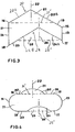
- the projection 21 is of any regular cross-sectional shape which has horizontal base, an imaginary 21' and a vertical axis of symmetry 22 such as a rectangle (Fig. 1), an isosceles triangle (Figs. 2 and 3), or a right circular arc (Fig.4).
- the lower surface of the block is correspondingly shaped to that of the upper surface rotated horizontally through one half of one revolution and consists of a narrow edge strip 23 and a wide bearing surface 24 each extending over the length of the block.
- the narrow edge strip 23 has similar dimensions to those of the upper surface edge strip 19 and extends either horizontally from the lower edge 18 of the rear face 14 or is inclined to the vertical plane containing the upper edge 16 and the lower edge 18 of the rear face 14 or is inclined to the vertical plane containing the upper edge 16 and the lower edge 18 of the rear face 14 at the same angle as the upper edge strip 19 is inclined to the vertical plane containing the upper edge 15 and the lower edge 17 of the front face 13.
- the wide bearing surface 24 is the same width as the upper surface wide bearing surface 20 and extends from the lower edge 17 of the front face 13 and respectively connects to or intersects with the horizontal or inclined narrow edge strip 23.
- the wide bearing surface 24 is provided with a recess 25 of dimensions which correspond to those of the upper surface projection 21 and which recess has an imaginary base 25' and a vertical axis of symmetry 26 horizontally displaced from the vertical axis of symmetry 22 of the projection by a distance equal to the plan width of the narrow edge strip 19 in the upper surface. This is also the plan width of the narrow edge strip 23 in the lower surface.
- the upper surface 20 comprises two substantially planar bearingsurfaces 20A, 20B disposed at an angle to each other to constitute a peaked roof shape 21 with a vertical axis of symmetry 22 and an extention 19 extending from the bearing surface 20B to the front face 13 of the block.
- the lower bearing surface 24 similarly comprises two substantially planar bearing surfaces 24A, 24B, disposed at an angle to each other to form a recess 25 complementary to the peaked roof shape 21 with a vertical axis of symmetry 26 and an extension 23 extending from the bearing surface 24B to the rear face 14.
- the axis of symmetry 22 and 26 are displaced laterally to each other by the width of the extension 19/23 and equally from the central longitudinal axis of the block.
- the upper planar surface 20A is equal in length to the lower planar surface 24A and the length of the upper planar surface 20B and its extension 19 is equal to the length of the lower planar surface 24B and its extension 23.
- the depth of the rear end face 14 is greater than that of the front face.
- Figs. 5 to 12 when a block is superimposed on a corresponding block in reversed orientation then the lower surface of the upper block bears fully on the upper surface of the lower block and is such that the projection 21 of the lower block nests into the recess 25 in the upper block and the upper surface narrow edge strip 19 of the lower block is in full contact with the lower surface narrow edge strip 23 of the upper block.
- Figs. 7 and 11 wherein three blocks alternating in orientation and each with a transverse section as shown respectively in Figs. 1 and 3, are built one on top of another thus to form a column with vertical sides.
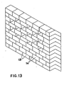
- Fig. 13 shows a free-standing wall structure constructed using blocks with a transverse section as shown in Fig. 3.
- Blocks in successive courses of the wall alternate in orientation thus providing a wall with vertical sides.
- the blocks in any course abut to give a closed face appearance whereas in the next five courses, blocks in any course are set less than a block length apart so that blocks in the next course span the gaps thus formed giving an open face appearance.
- each block abutts the adjacent block thus to form a continuous cope.
- Fig. 14 shows a part-sectional perspective view of a retaining wall structure constructed using blocks with a transverse section as shown in Fig. 3.
- the lowest or foundation course of blocks consists of blocks laid contiguously to permit a relatively even transfer of load to the subsoil or to an in-situ concrete foundation.
- the top course or coping course of blocks likewise has blocks laid contiguously as this is preferable both aesthetically and for protection of the wall interior from the affect of weather.
- the backfill material 27 can usefully be placed to cover over the rearward portion of a block up to the level of the upper surface projection 21.
- Blocks in each of the intermediate courses of the retaining wall are either laid contiguously or may be spaced apart depending on the weight of wall required to counteract the pressure from the retained material 28.
- a retaining wall of varying height blocks in any course may require to be closely spaced or abutting for high sections and spaced relatively further apart over low sections thus providing more economical use of blocks.
- the void behind the blocks is infilled with suitable material fill 27 up to the level of the upper edge of the rear face of the blocks and the fill material spills over the exposed upper surfaces of blocks in the superimposed course at least as far as the top of each block projection 21 thus giving additional weight to the wall structure.
- walls By laying two or more courses of blocks in like orientation side by side such that the rear faces 14 of blocks in one course abut with the front faces 13 of blocks in an adjacent course, walls can be constructed of increased width to cater for locations requiring higher walls and for walls with increased resistance against overturning and sideways displacement.
- a flexible synthetic sheeting material 29 can be placed between adjacent courses of units to reinforce the vertical joints.
- Blocks can usefully be provided with an extending orifice in order to locate steel bars, rope, cable or the like which can be used to reinforce courses of blocks, assist handling of the blocks and to 'lock' adjacent blocks together as is preferable in a wall cope.
- blocks according to the invention are normally used in upright orientation they may be oriented in any manner suitable for the purpose in hand. Indeed inverted blocks of transverse section as shown in Fig. 3 can be used to form surface water drainage channels and cascades.
- Construction blocks according to the invention are extremely versatile and unskilled labour can be used in any application thereof. Any structure built using the blocks may require blocks of different lengths to form vertical ends to the structure con- sistant with the provision of staggered vertical joints between adjacent courses.
Abstract
Description
- This invention concerns improvements in and relating to building blocks.
- An object of the present invention is to provide a building block which permits, without the use of a bonding agent between courses, the construction of free-standing walls which offer full or partial screening and the construction of retaining walls which have a stepped exposed face.
- Economy in the construction of mass gravity and crib retaining walls results when the walls are stepped or battered back against the material to be retained to such an extent that the resultant compressive stress over any transverse section of a wall foundation is uniform. A fully screened free-standing wall can be constructed by building concrete blocks or the like in courses with each block abutting. By providing gaps between blocks and/or by providing blocks with through-going orifices between exposed faces such a wall may become more decorative and less resistant to wind forces but offers less screening. Precast concrete blocks of various forms are currently used to construct retaining walls and screen walls and although cement mortar is commonly used to provide a bond between adjacent courses of blocks, other forms of block exist which are provided with suitably formed nibs and recesses so that a mechanical interlock is achieved between blocks. Hitherto more than one form of block has been required to construct dry bound free-standing screen walls and retaining walls.
- Building blocks are known from EP-A-0 034 565 which discloses a building block (see Figure 2) of uniform asymmetric transverse section comprising two vertical end faces, a front face and a rear face and upper and lower surfaces each having a bearing surface of equal width, the upper bearing surface having an extension thereof extending to the front face or the block and the lower bearing surface having an extension thereof extending to the rear face of the block whereby one block can be placed upon another block in like disposition so that the front extension of the lower block extends beyond the upper block or in a disposition of 180° to each other in which the front face of one block is vertically aligned with the rear face of the other block and the width of each bearing surface and its extension is equal to that of the other bearing surface and extension.
- Building blocks are known from DE 24 35 735 wherein upper and lower surfaces are of complementary shape.
- According to the invention, the building block is characterised in that an axis of symmetry of a projection in the upper bearing surface is displaced from an axis of symmetry of a recess in the lower bearing surface by the width of the extension of the upper/lower bearing surface.
- The invention also provides a free-standing vertical wall structure constructed using a plurality of such blocks in an alternating course sequence consisting of a course of blocks each laid with its front face exposed, superimposed on a course of blocks each laid with its rear face exposed or vice versa when viewed from either side of the structure.
- The invention further provides a retaining wall structure constructed using a plurality of such blocks in a course sequence consisting either of a course of blocks each laid with its front face exposed, superimposed on a like course of blocks or on an odd number of courses in which every odd course consists of blocks each with its front face exposed and every even course consists of blocks each with its rear face exposed.
- The accompanying drawings show by way of example various forms of block types and wall structure which can be constructed using blocks in accordance with the invention and wherein:-
- Figures 1 and 2 are elevations on one end and Figures 3 and 4 are elevations on the other end of four alternative shapes of a block according to the invention;
- Figures 5 and 6 are perspective views of a block of shape as in Fig. 2 in upright and in inverted orientation respectively;
- Figures 7 and 8 are perspective views of three blocks of shape as in Fig. 1 built to form a vertical sided column by reversing the orientation of alternate blocks and built to form a stepped structure using units of like orientation respectively;
- Figures 9. 10. 11 and 12 correspond to Figs. 5, 6 7 and 8 respectively but relate to a block of shape as in Fig. 3;
- Figure 13 is a perspective view of part of a free-standing wall built using blocks of shape as in Fig.3 and which wall is of open or partially screened form in the upper courses and is of closed form in the lower courses; and
- Figure 14 is a perspective view of part of a retaining wall built using blocks of shape as in Fig. 3.
- Referring to the drawings in general, the blocks may be moulded using concrete or any such mouldable material and may also be produced by extrusion using semi-dry mix concrete, asphalt, or the like.
- The block is of uniform transverse section and has opposed
vertical end faces front face 13 and therear face 14 may be vertical, concave, convex, ribbed or otherwise shaped but theupper edge 15 offront face 13 and theupper edge 16 ofrear face 14 are horizontal and are vertically disposed to their correspondinglower edges - Referring now to Figs. 1 to 4, the upper surface of the block is divided into a
narrow edge strip 19 and awide bearing surface 20 each extending over the length of the block. Thewide bearing surface 20 extends horizontally from theupper edge 16 of therear face 14 and occupies at least two thirds of the overall width of the block. Thenarrow edge strip 19 extends either horizontally Figs. 1, 2 and 4 from or is inclined (Fig. 3) to theupper edge 15 of thefront face 13 and respectively connects to or intersects with thewide bearing surface 20 and occupies not more than one third of the overall width of the block. The width of thenarrow edge strip 19 is related to the depth of thefront face 13 and determines the slope of the exposed face of a retaining wall constructed using a plurality of the blocks. Thewide bearing surface 20 is provided with aprojection 21 which may occupy all (Fig. 3) or only part of the width (Figs. 1, 2 and 4) of thebearing surface 20. Theprojection 21 is of any regular cross-sectional shape which has horizontal base, an imaginary 21' and a vertical axis ofsymmetry 22 such as a rectangle (Fig. 1), an isosceles triangle (Figs. 2 and 3), or a right circular arc (Fig.4). - The lower surface of the block is correspondingly shaped to that of the upper surface rotated horizontally through one half of one revolution and consists of a
narrow edge strip 23 and awide bearing surface 24 each extending over the length of the block. Thenarrow edge strip 23 has similar dimensions to those of the uppersurface edge strip 19 and extends either horizontally from thelower edge 18 of therear face 14 or is inclined to the vertical plane containing theupper edge 16 and thelower edge 18 of therear face 14 or is inclined to the vertical plane containing theupper edge 16 and thelower edge 18 of therear face 14 at the same angle as theupper edge strip 19 is inclined to the vertical plane containing theupper edge 15 and thelower edge 17 of thefront face 13. Thewide bearing surface 24 is the same width as the upper surfacewide bearing surface 20 and extends from thelower edge 17 of thefront face 13 and respectively connects to or intersects with the horizontal or inclinednarrow edge strip 23. Thewide bearing surface 24 is provided with arecess 25 of dimensions which correspond to those of theupper surface projection 21 and which recess has an imaginary base 25' and a vertical axis ofsymmetry 26 horizontally displaced from the vertical axis ofsymmetry 22 of the projection by a distance equal to the plan width of thenarrow edge strip 19 in the upper surface. This is also the plan width of thenarrow edge strip 23 in the lower surface. - Referring in particular to Fig. 3 there is shown a block in which the
upper surface 20 comprises two substantiallyplanar bearingsurfaces 20A, 20B disposed at an angle to each other to constitute apeaked roof shape 21 with a vertical axis ofsymmetry 22 and anextention 19 extending from the bearing surface 20B to thefront face 13 of the block. Thelower bearing surface 24 similarly comprises two substantially planar bearingsurfaces recess 25 complementary to thepeaked roof shape 21 with a vertical axis ofsymmetry 26 and anextension 23 extending from thebearing surface 24B to therear face 14. The axis ofsymmetry extension 19/23 and equally from the central longitudinal axis of the block. - The upper
planar surface 20A is equal in length to the lowerplanar surface 24A and the length of the upper planar surface 20B and itsextension 19 is equal to the length of the lowerplanar surface 24B and itsextension 23. The depth of therear end face 14 is greater than that of the front face. - Referring now to Figs. 5 to 12, when a block is superimposed on a corresponding block in reversed orientation then the lower surface of the upper block bears fully on the upper surface of the lower block and is such that the
projection 21 of the lower block nests into therecess 25 in the upper block and the upper surfacenarrow edge strip 19 of the lower block is in full contact with the lower surfacenarrow edge strip 23 of the upper block. This is illustrated in Figs. 7 and 11 wherein three blocks alternating in orientation and each with a transverse section as shown respectively in Figs. 1 and 3, are built one on top of another thus to form a column with vertical sides. - When a block is superimposed on a corresponding block of like orientation as shown in Figs. 8 and 12 then the
wide bearing surface 24 on the lower surface of the upper block bears directly on thewide bearing surface 20 of the lower block such that therecess 25 in the lower surface of the upper block provides a snug fit for theprojection 21 on the upper surface of the lower block. The upper block is thus laterally displaced relative to the lower block and causes thenarrow edge strip 19 of the upper surface of the lower block to be exposed. - Fig. 13 shows a free-standing wall structure constructed using blocks with a transverse section as shown in Fig. 3. Blocks in successive courses of the wall alternate in orientation thus providing a wall with vertical sides. In the lower four courses of the wall the blocks in any course abut to give a closed face appearance whereas in the next five courses, blocks in any course are set less than a block length apart so that blocks in the next course span the gaps thus formed giving an open face appearance. In the top course of the wall each block abutts the adjacent block thus to form a continuous cope.
- Fig. 14 shows a part-sectional perspective view of a retaining wall structure constructed using blocks with a transverse section as shown in Fig. 3. The lowest or foundation course of blocks consists of blocks laid contiguously to permit a relatively even transfer of load to the subsoil or to an in-situ concrete foundation. The top course or coping course of blocks likewise has blocks laid contiguously as this is preferable both aesthetically and for protection of the wall interior from the affect of weather. As a measure of protection against the removal of blocks in the coping course of such a wall by vandals, the
backfill material 27 can usefully be placed to cover over the rearward portion of a block up to the level of theupper surface projection 21. Blocks in each of the intermediate courses of the retaining wall are either laid contiguously or may be spaced apart depending on the weight of wall required to counteract the pressure from the retainedmaterial 28. In a retaining wall of varying height blocks in any course may require to be closely spaced or abutting for high sections and spaced relatively further apart over low sections thus providing more economical use of blocks. After laying each course of blocks in a retaining wall the void behind the blocks is infilled with suitable material fill 27 up to the level of the upper edge of the rear face of the blocks and the fill material spills over the exposed upper surfaces of blocks in the superimposed course at least as far as the top of eachblock projection 21 thus giving additional weight to the wall structure. - By laying two or more courses of blocks in like orientation side by side such that the rear faces 14 of blocks in one course abut with the
front faces 13 of blocks in an adjacent course, walls can be constructed of increased width to cater for locations requiring higher walls and for walls with increased resistance against overturning and sideways displacement. To ensure that a wall of multiple block width acts as a composite wall and to inhibit differential vertical displacement of adjacent courses of units, a flexiblesynthetic sheeting material 29 can be placed between adjacent courses of units to reinforce the vertical joints. - By choosing block dimensions such that the height of the
projection 21 is equal to or greater than the mean height of thefront face 13 and therear face 14 then even an 'open' faced wall built with such blocks will provide full visual screening although permitting passage of wind. - Blocks can usefully be provided with an extending orifice in order to locate steel bars, rope, cable or the like which can be used to reinforce courses of blocks, assist handling of the blocks and to 'lock' adjacent blocks together as is preferable in a wall cope.
- Although blocks according to the invention are normally used in upright orientation they may be oriented in any manner suitable for the purpose in hand. Indeed inverted blocks of transverse section as shown in Fig. 3 can be used to form surface water drainage channels and cascades.
- Construction blocks according to the invention are extremely versatile and unskilled labour can be used in any application thereof. Any structure built using the blocks may require blocks of different lengths to form vertical ends to the structure con- sistant with the provision of staggered vertical joints between adjacent courses.
Claims (6)
Priority Applications (1)
| Application Number | Priority Date | Filing Date | Title |
|---|---|---|---|
| AT85308134T ATE51262T1 (en) | 1984-11-08 | 1985-11-08 | BUILDING BLOCKS. |
Applications Claiming Priority (2)
| Application Number | Priority Date | Filing Date | Title |
|---|---|---|---|
| GB848428191A GB8428191D0 (en) | 1984-11-08 | 1984-11-08 | Building blocks |
| GB8428191 | 1984-11-08 |
Publications (3)
| Publication Number | Publication Date |
|---|---|
| EP0181230A2 EP0181230A2 (en) | 1986-05-14 |
| EP0181230A3 EP0181230A3 (en) | 1987-02-04 |
| EP0181230B1 true EP0181230B1 (en) | 1990-03-21 |
Family
ID=10569416
Family Applications (1)
| Application Number | Title | Priority Date | Filing Date |
|---|---|---|---|
| EP85308134A Expired - Lifetime EP0181230B1 (en) | 1984-11-08 | 1985-11-08 | Improvements in or relating to building blocks |
Country Status (4)
| Country | Link |
|---|---|
| EP (1) | EP0181230B1 (en) |
| AT (1) | ATE51262T1 (en) |
| DE (1) | DE3576713D1 (en) |
| GB (1) | GB8428191D0 (en) |
Families Citing this family (11)
| Publication number | Priority date | Publication date | Assignee | Title |
|---|---|---|---|---|
| DE3505530A1 (en) * | 1985-02-18 | 1986-08-21 | Sf-Vollverbundstein-Kooperation Gmbh, 2820 Bremen | (CONCRETE) MOLDED STONE FOR SUPPORT WALLS AND SUPPORT WALL |
| BE1006112A3 (en) * | 1992-08-07 | 1994-05-17 | Interblocs S P R L | Wall assembly and method for construction of the wall. |
| ES2111419B1 (en) * | 1994-01-19 | 1998-11-01 | Antonio Casado Y Cia S A A C Y | SET OF ELEMENTS FOR THE CONSTRUCTION OF RETAINING WALLS OF LAND AND CORRESPONDING ELEMENTS. |
| PT828899E (en) * | 1995-06-02 | 2003-12-31 | Novabrik Internat Inc | BLOCK FOR THE CONSTRUCTION OF A WALL WITHOUT MORTAR |
| GB9607611D0 (en) * | 1996-04-12 | 1996-06-12 | Clark Michael D | Improvements in and relating to building blocks |
| NZ332934A (en) * | 1996-05-09 | 2000-03-27 | Waldemar Szczepina | Interlocking building block with complementary faces at top/bottom and ends |
| AU679894B3 (en) * | 1996-09-06 | 1997-07-10 | Waldemar Szczepina | Self-locking, precision made, building block |
| EP1380700A1 (en) * | 2002-07-11 | 2004-01-14 | Marius Maranda | Antislip brick particularly suitable for antiseismic constructions |
| CA2469128C (en) * | 2004-05-28 | 2005-10-11 | Jagna Ltd. | Split key segmental retaining wall system |
| CN100359102C (en) * | 2004-07-07 | 2008-01-02 | 汪荣勋 | Permeable soil keeping wall and its use |
| CN101793071B (en) * | 2004-07-07 | 2013-11-13 | 汪荣勋 | Building block used for forming wall body structure |
Family Cites Families (9)
| Publication number | Priority date | Publication date | Assignee | Title |
|---|---|---|---|---|
| US3834108A (en) * | 1971-02-05 | 1974-09-10 | H Ludvigsen | Building element |
| DE2407621A1 (en) * | 1974-02-18 | 1975-08-21 | Karl Burr | Geometrically contoured building block - has parallel end faces and progressively varied sides providing interlock between blocks |
| DE2731228C2 (en) * | 1977-07-11 | 1983-02-03 | Sf-Vollverbundstein-Kooperation Gmbh, 2820 Bremen | Concrete shaped stone for the production of a retaining wall and retaining wall made of such shaped stones |
| DE8010258U1 (en) * | 1979-04-17 | 1980-09-25 | Baeni, Werner, Davos (Schweiz) | COMPONENT, PARTICULARLY CONCRETE |
| EP0034565B1 (en) * | 1980-02-11 | 1983-04-27 | Martin Mannhart | Wall built up with elements |
| DE3025870A1 (en) * | 1980-07-08 | 1982-02-04 | Georg Zürich Stulz | Vegetation supporting retaining wall hollow block - is trough shaped with sloping interfacing lengthways sides |
| DE3103849A1 (en) * | 1981-02-05 | 1982-09-09 | Ed. Züblin AG, 7000 Stuttgart | Securing structure for steep slopes and walls in which vegetation can grow |
| DE3138155A1 (en) * | 1981-09-25 | 1983-04-14 | Couwenbergs, Paul, Dr., 7500 Karlsruhe | Block, in particular artificial block |
| CA1194703A (en) * | 1983-06-14 | 1985-10-08 | Andre Hamel | Block for the construction of retaining walls |
-
1984
- 1984-11-08 GB GB848428191A patent/GB8428191D0/en active Pending
-
1985
- 1985-11-08 EP EP85308134A patent/EP0181230B1/en not_active Expired - Lifetime
- 1985-11-08 DE DE8585308134T patent/DE3576713D1/en not_active Expired - Fee Related
- 1985-11-08 AT AT85308134T patent/ATE51262T1/en not_active IP Right Cessation
Also Published As
| Publication number | Publication date |
|---|---|
| GB8428191D0 (en) | 1984-12-19 |
| EP0181230A3 (en) | 1987-02-04 |
| EP0181230A2 (en) | 1986-05-14 |
| DE3576713D1 (en) | 1990-04-26 |
| ATE51262T1 (en) | 1990-04-15 |
Similar Documents
| Publication | Publication Date | Title |
|---|---|---|
| USRE37278E1 (en) | Retaining wall block | |
| CA2231567C (en) | Concrete block | |
| EP0020721B1 (en) | Precast concrete structural unit and composite wall structure | |
| CA2143234C (en) | Dry-stackable masonry unit and methods of manufacture and use | |
| AU634169B2 (en) | Self-supporting interconnectable formwork elements for the casting of especially wall constructions and a method for the use of said formwork elements | |
| US5623797A (en) | Block structure and system for arranging above-ground fencing, railing and/or sound barriers | |
| CA1229994A (en) | Building blocks | |
| US5865006A (en) | Retaining wall block and wall construction | |
| US4597236A (en) | Hollow wall construction | |
| EP0181230B1 (en) | Improvements in or relating to building blocks | |
| US6010279A (en) | Retaining wall construction | |
| AU684312B2 (en) | Block wall system | |
| CA3106531A1 (en) | Wall blocks, veneer panels for wall blocks and method of constructing walls | |
| US3435576A (en) | Interlocking building block | |
| US4932812A (en) | Intermeshable construction unit | |
| US4318642A (en) | Walls | |
| US4703599A (en) | Concrete masonry footer block foundation system and blocks therefor | |
| US3314208A (en) | Grouted masonry wall | |
| US4798036A (en) | Concrete masonry footer block foundation system and blocks therefor | |
| US5480267A (en) | Set of structural elements made up of concrete blocks, and a gravity retaining wall erected therefrom | |
| SU1145106A1 (en) | Wall block | |
| US4719737A (en) | Interlocking construction block | |
| EP0227359B1 (en) | Architectural arch | |
| EP0892875B1 (en) | Improvements in and relating to building blocks | |
| US2851874A (en) | Reinforced concrete building construction |
Legal Events
| Date | Code | Title | Description |
|---|---|---|---|
| PUAI | Public reference made under article 153(3) epc to a published international application that has entered the european phase |
Free format text: ORIGINAL CODE: 0009012 |
|
| AK | Designated contracting states |
Kind code of ref document: A2 Designated state(s): AT BE CH DE FR GB IT LI |
|
| PUAL | Search report despatched |
Free format text: ORIGINAL CODE: 0009013 |
|
| AK | Designated contracting states |
Kind code of ref document: A3 Designated state(s): AT BE CH DE FR GB IT LI |
|
| 17P | Request for examination filed |
Effective date: 19870727 |
|
| 17Q | First examination report despatched |
Effective date: 19880426 |
|
| GRAA | (expected) grant |
Free format text: ORIGINAL CODE: 0009210 |
|
| AK | Designated contracting states |
Kind code of ref document: B1 Designated state(s): AT BE CH DE FR GB IT LI |
|
| PG25 | Lapsed in a contracting state [announced via postgrant information from national office to epo] |
Ref country code: LI Effective date: 19900321 Ref country code: IT Free format text: LAPSE BECAUSE OF FAILURE TO SUBMIT A TRANSLATION OF THE DESCRIPTION OR TO PAY THE FEE WITHIN THE PRESCRIBED TIME-LIMIT;WARNING: LAPSES OF ITALIAN PATENTS WITH EFFECTIVE DATE BEFORE 2007 MAY HAVE OCCURRED AT ANY TIME BEFORE 2007. THE CORRECT EFFECTIVE DATE MAY BE DIFFERENT FROM THE ONE RECORDED. Effective date: 19900321 Ref country code: CH Effective date: 19900321 Ref country code: BE Effective date: 19900321 Ref country code: AT Effective date: 19900321 |
|
| REF | Corresponds to: |
Ref document number: 51262 Country of ref document: AT Date of ref document: 19900415 Kind code of ref document: T |
|
| REF | Corresponds to: |
Ref document number: 3576713 Country of ref document: DE Date of ref document: 19900426 |
|
| REG | Reference to a national code |
Ref country code: CH Ref legal event code: PL |
|
| ET | Fr: translation filed | ||
| PLBE | No opposition filed within time limit |
Free format text: ORIGINAL CODE: 0009261 |
|
| STAA | Information on the status of an ep patent application or granted ep patent |
Free format text: STATUS: NO OPPOSITION FILED WITHIN TIME LIMIT |
|
| 26N | No opposition filed | ||
| PGFP | Annual fee paid to national office [announced via postgrant information from national office to epo] |
Ref country code: FR Payment date: 19911129 Year of fee payment: 7 |
|
| PGFP | Annual fee paid to national office [announced via postgrant information from national office to epo] |
Ref country code: DE Payment date: 19920422 Year of fee payment: 7 |
|
| PG25 | Lapsed in a contracting state [announced via postgrant information from national office to epo] |
Ref country code: FR Effective date: 19930730 |
|
| PG25 | Lapsed in a contracting state [announced via postgrant information from national office to epo] |
Ref country code: DE Effective date: 19930803 |
|
| REG | Reference to a national code |
Ref country code: FR Ref legal event code: ST |
|
| REG | Reference to a national code |
Ref country code: GB Ref legal event code: IF02 |
|
| PGFP | Annual fee paid to national office [announced via postgrant information from national office to epo] |
Ref country code: GB Payment date: 20021106 Year of fee payment: 18 |
|
| PG25 | Lapsed in a contracting state [announced via postgrant information from national office to epo] |
Ref country code: GB Free format text: LAPSE BECAUSE OF NON-PAYMENT OF DUE FEES Effective date: 20031108 |
|
| GBPC | Gb: european patent ceased through non-payment of renewal fee |
Effective date: 20031108 |