EP0180484A2 - Elektrischer Steckverbinder - Google Patents
Elektrischer Steckverbinder Download PDFInfo
- Publication number
- EP0180484A2 EP0180484A2 EP19850307966 EP85307966A EP0180484A2 EP 0180484 A2 EP0180484 A2 EP 0180484A2 EP 19850307966 EP19850307966 EP 19850307966 EP 85307966 A EP85307966 A EP 85307966A EP 0180484 A2 EP0180484 A2 EP 0180484A2
- Authority
- EP
- European Patent Office
- Prior art keywords
- connector
- connection portion
- conductor connection
- spring means
- cavity
- Prior art date
- Legal status (The legal status is an assumption and is not a legal conclusion. Google has not performed a legal analysis and makes no representation as to the accuracy of the status listed.)
- Withdrawn
Links
- 239000004020 conductor Substances 0.000 claims abstract description 41
- 230000001154 acute effect Effects 0.000 claims description 5
- 239000000463 material Substances 0.000 claims description 4
- 239000004033 plastic Substances 0.000 claims description 2
- 229920003023 plastic Polymers 0.000 claims description 2
- 238000004873 anchoring Methods 0.000 claims 1
- 230000000717 retained effect Effects 0.000 abstract description 3
- 238000003780 insertion Methods 0.000 description 4
- 230000037431 insertion Effects 0.000 description 4
- 238000010618 wire wrap Methods 0.000 description 3
- 239000002184 metal Substances 0.000 description 2
- 230000000694 effects Effects 0.000 description 1
- 238000010292 electrical insulation Methods 0.000 description 1
- 239000011810 insulating material Substances 0.000 description 1
- 230000014759 maintenance of location Effects 0.000 description 1
- 238000000034 method Methods 0.000 description 1
- 229920005668 polycarbonate resin Polymers 0.000 description 1
- 239000004431 polycarbonate resin Substances 0.000 description 1
- 239000007787 solid Substances 0.000 description 1
Images
Classifications
-
- H—ELECTRICITY
- H01—ELECTRIC ELEMENTS
- H01R—ELECTRICALLY-CONDUCTIVE CONNECTIONS; STRUCTURAL ASSOCIATIONS OF A PLURALITY OF MUTUALLY-INSULATED ELECTRICAL CONNECTING ELEMENTS; COUPLING DEVICES; CURRENT COLLECTORS
- H01R13/00—Details of coupling devices of the kinds covered by groups H01R12/70 or H01R24/00 - H01R33/00
- H01R13/40—Securing contact members in or to a base or case; Insulating of contact members
- H01R13/42—Securing in a demountable manner
- H01R13/428—Securing in a demountable manner by resilient locking means on the contact members; by locking means on resilient contact members
- H01R13/432—Securing in a demountable manner by resilient locking means on the contact members; by locking means on resilient contact members by stamped-out resilient tongue snapping behind shoulder in base or case
-
- H—ELECTRICITY
- H01—ELECTRIC ELEMENTS
- H01R—ELECTRICALLY-CONDUCTIVE CONNECTIONS; STRUCTURAL ASSOCIATIONS OF A PLURALITY OF MUTUALLY-INSULATED ELECTRICAL CONNECTING ELEMENTS; COUPLING DEVICES; CURRENT COLLECTORS
- H01R4/00—Electrically-conductive connections between two or more conductive members in direct contact, i.e. touching one another; Means for effecting or maintaining such contact; Electrically-conductive connections having two or more spaced connecting locations for conductors and using contact members penetrating insulation
- H01R4/24—Connections using contact members penetrating or cutting insulation or cable strands
- H01R4/2416—Connections using contact members penetrating or cutting insulation or cable strands the contact members having insulation-cutting edges, e.g. of tuning fork type
- H01R4/242—Connections using contact members penetrating or cutting insulation or cable strands the contact members having insulation-cutting edges, e.g. of tuning fork type the contact members being plates having a single slot
- H01R4/2425—Flat plates, e.g. multi-layered flat plates
- H01R4/2429—Flat plates, e.g. multi-layered flat plates mounted in an insulating base
Definitions
- This invention relates to an improved electrical connector and more particularly to a means which allows tne connector to be retained in a slot or aperture into which it is inserted while at the same tine allowing for the connector to be easily removed or disengaged from the slot.
- Terminal connecting blocks are used extensively in the fields of electronics and communications. For example, they are used by the telephone industry in distribution cabinets for connecting conductors in a cable from an exchange to other conductors extending to various stations within a building. Such connecting blocks should be as compact as possible so as to take up a minimum amount of space while providing means for making a large number of connections. The connectors should be easily insertable in the block, be retained in the block without excessive motion once they are inserted, and readily removable without causing harm to the block.
- Connectors which provide connections for one or more conductors are well known. Most of those connectors which provide connections for a multiple number of conductors are of the type which comprise two or more beam type spring members attached to the main body of the connector. Examples of such connectors are shown in U.S. Patent Numbers 3,605,071 which issued on September 14, 1971 and 3,761,866 which issued on September 25, 1973 both in the name of William Sedlacek. Further examples of such connectors are shown in U.S. Patent Number 4,350,405 which issued on September 21, 1982 in the name of C. Yapoudjian et al and U.S. Patent Number 4,421,374 which issued on December 20, 1983 in the name of L. Montilla Jr., et al.
- an electrical connector of electrically conductive material said connector being characterised in that it comprises a conductor connection portion extending in one direction and having a base portion at one end for receiving at least one electrical conductor in electrical connection therewith; an intermediate portion having two ends, one of said ends being connected to said conductor connection portion at said base portion and being unitary therewith, said intermediate portion extending from said conductor connection portion in a direction which is substantially opposite the direction in which said conductor connection portion extends; and spring means having a predetermined length and connected at one end to said intermediate portion at the other of the two ends of said intermediate portion in a manner such that said spring means extends outwardly therefrom toward said base portion of the conductor connection portion, said predetermined length being such that said spring means terminates at its free end short of said base portion of said conductor connection portion.
- the invention also provides a connector assembly comprising a supporting block of electrically insulative material having an aperture therein in which an electrical connector as defined in the preceding paragraph is mounted with the spring means thereof positioned inside and engaged within a cavity of the aperture.
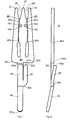
- FIGs. 1 and 2 there is shown an electrical connector 10 of the type which provides connections for a multiple number of conductors in the form of an integral spring metal piece.
- the connector 10 may be constructed of any suitable resilient conducting material.
- the connector may be formed by known metal stamping methods.
- the connector is comprised of a flat base portion 40 and three contact fingers projecting therefrom.
- the fingers include a symmetrical center finger 14 and left side and right side fingers 12 and 16, respectively. Slots are provided between the fingers,left slot 22 having a first portion 22a and a second portion 22b and right slot 24 having a first portion 24a and a second portion 24b.
- the tips of the left and center fingers define an essentially V-shaped tapered mouth 26 for slot 22.
- the tips of the center and right fingers also define an essentially V-shaped tapered mouth 28 for slot 24.
- the mouths 26 and 28 facilitate the introduction of an electrical conductor (not shown) into its associated slot.
- an electrical conductor not shown
- the respective resilient side finger 12 or 16 and the center finger 14 are pushed apart. The electrical insulation on the conductor is crushed and abraded away so as to cause an electrical contact between the connector 10 and the conductor.
- Center finger 14 also includes crushed portions 14a and 14b. These crushed portions form associated bosses 14c and 14d, respectively. These bosses allow for better retention of a conductor inserted in slot 22 or 24 in that the projection of the associated crushed portion 14a or 14b forms a mechanical abutment. This abutment is in addition to the mechanical pressure exerted on the conductor by the fingers of the connection fork.
- the lower end of the connector may include a terminal end 30 to permit a soldered connection or a wire wrapped connection.
- the terminal 30 is joined to base 40 by an intermediate part 34 of connector 10 and lies in a plane which is at a shallow acute angle with respect to the plane in which base portion 40 lies.
- connector 10 includes a cantilever spring member 32.
- Spring member 32 extends outwardly from the interface between terminal end 30 and intermediate part 34 toward flat base portion 40.
- Spring member 32 lies in a plane which is at a shallow acute angle with respect to the plane in which base portion 40 lies, and extends in the opposite direction to terminal end 30. This angle is sufficient, however, to allow member 32 to pass beyond the thickness 40f of base portion 40.
- the length of spring member 32 is such that its upper edge 32a falls just below the lower edge 40a of base portion 40. In this manner the base portion does not interfere with the operation of the cantilever spring.
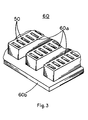
- FIG. 3 there is shown a perspective view of a connector block 60 having a plurality of apertures or slots 50 in which the connectors 10 are mounted.
- the block 60 which has a top surface 60a and a bottom surface 60b, may be formed of a suitable electrical insulating material such as a plastic, e.g., polycarbonate resin.
- the block 60 contains a multiplicity of slots 50 extending through the thickness of the block.
- the slots 50 are adapted to receive the connector 10. These slots are arranged in a geometrical pattern designed to accommodate a maximum number of connectors in a minimum amount of space.
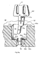
- FIG. 4a shows the cross-section looking in one direction.
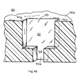
- Fig. 4b shows the cross-section looking in the opposite direction.
- a portion of connector 10 is shown in Fig. 4a but has been omitted from Fig. 4b for ease of illustration.
- Slot 50 includes a first substantially rectangular shaped portion 52 which is adapted to accept base portion 40 of connector 10.
- the dimensions of the portion 52 are such that the lower edge 40a of base portion 40 abuts the bottom edge 52a of portion when the connector is fully inserted in the slot.
- the dimensions of the first portion 52 and the connector 10 are also such that when the connector is fully inserted in slot 50 only the first portion 22a, 24a and tips of the fingers 12, 14, 16 (see Fig. 1) project beyond the top surface 60a of the block.
- Slot 50 includes a second portion 54 which lies below first portion 52.
- the portion 54 is adapted to accept that part of the connector 10 which lies below base 40.
- Portion 54 is in effect an extension of and lies in the same plane as portion 52.
- Slot 50 further includes, as shown in Fig. 4a, a cavity 56 which is adapted to receive cantilever spring member 32.
- Cavity 56 is essentially rectangular and is recessed at a predetermined depth from portions 52 and 54. The depth of cavity 56 is such that the upper edge 32a of angled spring member 32 clears the upper end 56a of the cavity when connector 10 is fully seated in slot 50.
- Cavity 56 is windowless in that block 60 is solid as shown in Fig. 3.
- terminal end 30 is formed at an angle opposite to the angle at which spring member 32 is formed. End 30 is formed in this manner for a predetermined angle in order that it match or exceed the depth of portion 52.
- the advantage in forming end 30 in this manner is that it facilitates insertion of the connector in the slot.
- angled end 30 is forced against surface 54a of portion 54 (see Fig. 4b). In this manner end 30 will not slide into cavity 56 and become lodged therein. The lodging of end 30 in cavity 56 might occur if end 30 were not at an angle with respect to base portion 40. In that case it would become necessary to apply increased external force to connector 10 in order to dislodge end 30 from cavity 56.
- the angling of terminal end 3Q while not critical to the invention, does allow for ease of insertion of the connector into the slot.
- Portion 54 and cavity 56 are equal in length and that length is such that when the connector is fully seated in the slot the lower edge 32b of the spring member and the portion of terminal end 30 adjacent thereto both project beyond the bottom surface 60b of the block.
- the spring member 32 is angled downward from its lower edge 32b toward the back end 56b of cavity 56.
- the upper and lower edges, 32a and 32b, respectively, of spring member 32 do not ordinarily contact the back end 56b.
- the space between the lower edge of the spring member and end 56b allows an appropriately shaped tool to be inserted into cavity 56 from the bottom surface of the block.
- the tool is used to force spring member 32 upwardly such that its upper edge 32a clears the upper end 56a of the cavity. In this manner connector 10 can then easily be removed from slot 50 by sliding the connector upwardly toward the top surface of the block.
- connector 10 may include rounded edge 30a on its terminal end 30, a rounded edge for lower edge 32b of spring member 32, and rounded edges 40b, 40c, 40d and 40e on its base portion 40. It has been found that the use of such rounded edges facilitates insertion of the connector into its associated slot.
- Slot 50 may also include rounded edges (not shown) for one or more of the edges designated as 50a and 50b in Figs. 4a and 4b. These rounded edges also facilitate insertion of the connector in the slot.
Landscapes
- Connector Housings Or Holding Contact Members (AREA)
Applications Claiming Priority (2)
| Application Number | Priority Date | Filing Date | Title |
|---|---|---|---|
| US66784784A | 1984-11-02 | 1984-11-02 | |
| US667847 | 1984-11-02 |
Publications (1)
| Publication Number | Publication Date |
|---|---|
| EP0180484A2 true EP0180484A2 (de) | 1986-05-07 |
Family
ID=24679901
Family Applications (1)
| Application Number | Title | Priority Date | Filing Date |
|---|---|---|---|
| EP19850307966 Withdrawn EP0180484A2 (de) | 1984-11-02 | 1985-11-01 | Elektrischer Steckverbinder |
Country Status (2)
| Country | Link |
|---|---|
| EP (1) | EP0180484A2 (de) |
| JP (1) | JPS61153962A (de) |
Cited By (1)
| Publication number | Priority date | Publication date | Assignee | Title |
|---|---|---|---|---|
| US5035650A (en) * | 1990-06-15 | 1991-07-30 | Amp Incorporated | Electrical connector having an inner metal shield |
-
1985
- 1985-10-30 JP JP24173985A patent/JPS61153962A/ja active Pending
- 1985-11-01 EP EP19850307966 patent/EP0180484A2/de not_active Withdrawn
Cited By (1)
| Publication number | Priority date | Publication date | Assignee | Title |
|---|---|---|---|---|
| US5035650A (en) * | 1990-06-15 | 1991-07-30 | Amp Incorporated | Electrical connector having an inner metal shield |
Also Published As
| Publication number | Publication date |
|---|---|
| JPS61153962A (ja) | 1986-07-12 |
Similar Documents
| Publication | Publication Date | Title |
|---|---|---|
| EP0452061B1 (de) | Elektrischer Mehrfachleiter-Verbinder mit ausgestanzten und geformten Kontakten | |
| US4428636A (en) | Multi-contact connectors for closely spaced conductors | |
| US5564952A (en) | Electrical plug connector with blade receiving slots | |
| EP0021731B1 (de) | Elektrisches Kontaktelement und mit solchen Kontaktelementen versehener Verbinder | |
| US3860318A (en) | Pre-loaded electrical connector | |
| US4566749A (en) | Electrical connector receptacle | |
| EP0001159A1 (de) | Elektrischer Verbinder | |
| US5697815A (en) | Electrical connectors | |
| US3444504A (en) | Electrical connector having stabilizing means and free-floating contact section | |
| CA1146231A (en) | Electrical plug receptacle connector | |
| EP0608851A2 (de) | Elektrische Kontaktstruktur mit geringer Einsteckkraft | |
| EP0601577B1 (de) | Elektrisches Verbindungselement für Flachbandkabel | |
| EP0232521A2 (de) | Flachbaubuchse | |
| US3275765A (en) | Electrical connecting and switch device | |
| US4405193A (en) | Preloaded electrical connector | |
| US4648678A (en) | Electrical connector | |
| EP0740372B1 (de) | Elektrischer Verbinder | |
| CA1190295A (en) | Electrical termination system and connector member | |
| EP0191539A2 (de) | Elektrisches Anschlussendstück für Steckverbinder | |
| EP0527399A1 (de) | Schneidklemmkontakt | |
| EP0372767A1 (de) | Isolationsdurchdringender elektrischer Miniaturkontakt | |
| EP0136123A1 (de) | Elektrischer Verbinder zum Stecken auf drei senkrecht angeordneten Anschlusslaschen | |
| EP0109297B1 (de) | Elektrische Kontaktorgane und Zusammenbau elektrischer Verbinder | |
| GB2294817A (en) | Electrical terminal and connector assembly | |
| GB2100072A (en) | Insulation piercing terminal |
Legal Events
| Date | Code | Title | Description |
|---|---|---|---|
| PUAI | Public reference made under article 153(3) epc to a published international application that has entered the european phase |
Free format text: ORIGINAL CODE: 0009012 |
|
| AK | Designated contracting states |
Kind code of ref document: A2 Designated state(s): DE GB SE |
|
| STAA | Information on the status of an ep patent application or granted ep patent |
Free format text: STATUS: THE APPLICATION HAS BEEN WITHDRAWN |
|
| 18W | Application withdrawn |
Withdrawal date: 19861017 |
|
| RIN1 | Information on inventor provided before grant (corrected) |
Inventor name: SUFFI, LOUIS |