EP0180482A2 - Méthode pour l'évaluation d'os - Google Patents
Méthode pour l'évaluation d'os Download PDFInfo
- Publication number
- EP0180482A2 EP0180482A2 EP85307943A EP85307943A EP0180482A2 EP 0180482 A2 EP0180482 A2 EP 0180482A2 EP 85307943 A EP85307943 A EP 85307943A EP 85307943 A EP85307943 A EP 85307943A EP 0180482 A2 EP0180482 A2 EP 0180482A2
- Authority
- EP
- European Patent Office
- Prior art keywords
- bone
- pattern
- limb
- density distribution
- density
- Prior art date
- Legal status (The legal status is an assumption and is not a legal conclusion. Google has not performed a legal analysis and makes no representation as to the accuracy of the status listed.)
- Ceased
Links
Images


Classifications
-
- A—HUMAN NECESSITIES
- A61—MEDICAL OR VETERINARY SCIENCE; HYGIENE
- A61B—DIAGNOSIS; SURGERY; IDENTIFICATION
- A61B6/00—Apparatus for radiation diagnosis, e.g. combined with radiation therapy equipment
- A61B6/50—Clinical applications
- A61B6/505—Clinical applications involving diagnosis of bone
-
- G—PHYSICS
- G06—COMPUTING; CALCULATING OR COUNTING
- G06T—IMAGE DATA PROCESSING OR GENERATION, IN GENERAL
- G06T7/00—Image analysis
Definitions
- the present invention relates to a bone evaluation method. More specifically, it relates to a bone evaluation method in which a bone pattern is determined by measuring the photodensity of X-ray photographs of the long shank bone of a limb or by photon absorption metory from the long shank bone of a limb, the resultant bone pattern is modified, and the bone is evaluated based on the resultant modified bone pattern.
- the so-called MD method has heretofore known as a method for evaluating bone, for example, growth conditions of human bone, aging degree of human bone, or kinds of bone diseases such as osteoporosis and osteomalacia, as disclosed in, for example, "Kotsu Taisha” (i.e., Bone Metabolism) 13, pp 187-195 (1980) and 14, pp 91-104, (1981).
- the photodensity of X-ray photographs is measured at the middle site of a metacarpal bone with a microdensitometer and various indices such as an index of the bone cortical width (MCI), a bone width (D), a maximum bone density (GSmax), a minimum bone density (GSmin), a bone mineral content (EGS), and an average bone density (EGS/D) are determined.
- MCI bone cortical width
- D bone width
- GSmax maximum bone density
- GSmin minimum bone density
- EVS bone mineral content
- EVS/D average bone density
- Another known method for evaluating bone is so-called photon absorption metory. According to this method, a y-ray is used instead of an X-ray and the amount of the y-ray transmitted through bone is measured by a detector, followed by a quantitative treatment.
- GSmax maximum bone density
- MCI bone cortical width
- BMC bone mineral content
- the objects of the present invention are to eliminate the above-mentioned disadvantages of the conventional bone evaluation methods and to provide a novel bone evaluation method capable of reliably evaluating bone by using indices directly reflecting the conditions of bone with good reproducibility.
- a method for evaluating bone comprising the steps of:
- a method for evaluating bone comprising the steps of:
- a bone pattern is first determined in the step (a) by measuring the photodensity of an X-ray photograph of the long shank bone of a limb or by photon absorption metory from the long shank bone of a limb.
- the use of bones covered with soft tissues having a thin and average thickness is preferable.
- bones are the first through fifth metacarpal bones, especially the mid-shafts of the second metacarpal bones.
- the X-ray photograph can be taken by any conventional X-ray photographic method and the desired bone pattern can be obtained by measuring the photodensity of the resultant X-ray photograph.
- the bone pattern can be determined according to a conventional MD method.
- the photodensities of the X-ray photographic image are measured, together with the X-ray photographic image of an aluminum step wedge consisting of, for example, 20 steps each having a minimum height of 1 mm (i.e., from a lowest height of 1 mm, to a total height of 20 mm) or aluminum slope, with a densitometer.
- the aluminum step wedge is placed besides bones to be examined and the X-ray photographic image is taken of the bones and wedge together.
- the photodensity is preferably measured between the nearest end and the farthest end of the bone.
- the photodensities thus measured are plotted at an enlarged scale on a graphical paper graduated with an optical density (OD) and the optical absorbance (OD) in each point of the bone is converted to the corresponding aluminum step of the aluminum step wedge (i.e., GS value) to obtain the bone pattern as shown in Fig. 1 (see “Kotsu Taisha” (Bone Metabolism) 13, pp 187-195 (1980); ibid 14, pp 91-104 (1981); and ibid 14, pp 319-325 (1981)).
- the bone pattern can be obtained by reading the X-ray photographic image of the bone, together with the X-ray photographic image of the aluminum step wedge or aluminum slope, by a TV camera.
- the bone pattern can be determined from the long shank bone of a limb by photon absorption metory.
- a photon absorption metory method a y-ray is used instead of an X-ray and the amount of the y-ray transmitted through the bone is measured by a detector (see “Jin to Toseki” (i.e., Kidney and Dialysis) Vol. 6, No. 1, pp 49 (1979) and "Science” Vol. 142, pp 230 (1963)).
- the cross-section of the long shank bone of a limb is scanned by a y-ray and the count numbers of the y-ray transmitted through the bone are drawn as an image as shown in Fig. 1.
- the bone pattern obtained above is then modified in step (b) by smoothing and symmetrizing the bone pattern.
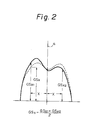
- the symmetrization of the bone pattern will now be explained with reference to Fig. 2. That is, the center line (a) is drawn in the bone pattern (i.e., the solid line in Fig. 2) obtained by the above-mentioned step (a).
- the GS values i.e., GSx l and GSx 2
- This procedure is repeated by changing the distance X.
- the symmetrized bone pattern i.e., the dotted line in Fig. 2 is obtained.
- the symmetrized bone pattern thus obtained is then smoothed or standardized.
- the smoothing of the symmetrized bone pattern will now be explained with reference to Fig. 3. That is, the bone pattern symmetrized above is equally divided in width. For example, a portion of the bone pattern is divided into five sections Xi l , Xi 2 , Xi 3 , Xi 4 , and Xi 5 . Then, the GS values at these points (i.e., GSxi l , GSxi 2 , GSxi 3 , GSxi 4 , and GSxi 5 ) are determined and the average of these GS values is calculated.
- the average GS value is designated as a GS value at the point Xi 3 . This procedure is repeated and the resultant average GS values in each portion are plotted to obtain the smoothed bone pattern curve. This smoothing method is carried out according to the so-called moving-average method.
- the GS value is determined as ln (I 0 /I i ), wherein I 0 is a count number of the y-ray transmitted through the bone and I i is a count number of the incident y-ray.
- indices are determined from the modified bone pattern obtained in the above-mentioned step (b).
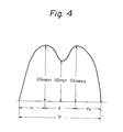
- the indices obtained in the case of the second metacarpal bone will now be explained with reference to Fig. 4.
- D represents a bone width
- d a bone marrow width
- d 1 a width of a ulnar side bone cortex
- d 2 a width of a radial side bone cortex.
- the index MCI can be determined according to the following equation.
- GSmin represents a minimum bone density.
- the maximum bone density GSmax is determined as an average of GSmax, in Fig. 4 (i.e., the minimum GS value in the ulnar side bone cortex) and GSmax 2 in Fig. 4 (i.e., the maximum GS value in the raidal side bone cortex) as follows.
- GSmax l should be equal to GSmax 2 due to the above-mentioned symmetrization of the bone pattern.
- the index EGS can be obtained by integrating each GS value and the average bone density EG S/D or EGS/D 2 can be obtained from the bone mineral density value thus obtained.
- the desired evaluation of bone can be effected by using at least one index selected from the above-mentioned indices, i.e., MCI, D, GSmax, GSmin, ZGS, and EGS/D or ⁇ GS/D 2 .
- indices for example, the bone cortical width index (MCI)
- MCI bone cortical width index
- a more accurate bone evaluation can be effected according to the present invention.
- the practical evaluation can be carried out based on any known method.
- the evaluation method of osteanabrosis is disclosed in "Kotsu Taisha” (Bone Metabolism) 13, 187-195 (1980).
- the evaluation of bone growth can be carried out according to a method disclosed in, for example, "Kotsu Taisha” (Bone Metabolism) 14, 319-325 (1981).
- the bone is evaluated by (a) determining a bone pattern (i) by measuring the photodensity of an X-ray photograph of the long shank bone of a limb or (ii) by photon absorption metory from the long shank bone of a limb; (b) smoothing and symmetrizing the bone pattern to modify the same; (c) determining a bone density distribution by setting a bone model having an elliptic bone cross-sectional external shape, a zonate bone cortex, and a bone density decreasing portion in the inside of the bone cortex from the modified bone pattern; and (d) evaluating the bone based on the bone density distribution.
- the bone pattern is first determined from the long shank bone of a limb by the X-ray photography or photon absorption metory and the resultant bone pattern is then symmetrized or smoothed to obtain a modified bone pattern in the same manner as the steps (a) and (b) of the first aspect of the present invention.
- a bone density distribution is determined by setting a bone model having an elliptic bone cross-sectional external shape, a zonate bone cortex, and a bone density decreasing portion in the inside of the bone cortex from the modified bone pattern.
- the modified bone pattern obtained above is first converted to an elliptic bone model as shown-in Fig. 5.
- the ellipic form is an external shape of a certain cross-section of the bone.
- the preferable ratio of major axis/minor axis of the elliptic shape is more than 1 but not more than 1.4.
- the use of an elliptic shape having a ratio of major axis/minor axis of around 1.25 is especially preferable due to good matching to the actual bone.
- the use of an elliptic shape having a ratio of major axis/minor axis near 1 is preferable.
- the elliptic bone pattern is divided in n equal sections.
- the ulnar side of the bone pattern is divided in 100 equal sections in Fig. 5.
- the bone densities in each layer in Fig. 5 are designated as ⁇ ' 1 , ⁇ ' 2 , ⁇ ' 3 , ... ⁇ ' i ... , and ⁇ , 100 .
- the bone model is set so as to have a zonate bone cortex and the bone density in each zone is assumed to be constant.
- the bone density in a phase located at the equal distance from the outer periphery of the cross-section of the bone is assumed to be the same.
- the length of the cross-section of the bone model at each position divided in n equal sections can be represented as follows.
- the values such as I l , l ' I 2 , 1 ' ... can be easily determined from the ratio of major axis/minor axis of the elliptic shape by a conventional method. From these values, the following recurrence formulae can be obtained. These formulae are in the case of the bone pattern being divided in 100 equal sections.
- the bone density ( ⁇ i ') in each position can be obtained by solving the above-mentioned recurrence formulae and the bone density distribution can be obtained by graphically illustrating these formulae.
- the dotted line in Fig. 5 illustrates the bone density distribution thus obtained.
- the bone pattern of a portion in which the bone density is homogeneous in the exterior of the bone cortex is selected and, then, the above-mentioned recurrence formulae can be solved by assuming that the bone density in the selected portion is constant. Furthermore, since both end portions of the bone pattern include large errors due to the influence of scattered light, these portions are negligible and the more correct value can be determined upon neglecting both end portions.
- the symmetrization of the bone pattern according to the present invention can be omitted and the calculation can be carried out by using a bone pattern only in the radial bone side and by applying, to the bone model, only a portion which can be approximated by an elliptic shape.
- the bone density ( ⁇ i ') obtained above is obtained based on a GS value, which is derived by comparing the photodensity of the X-ray image with that of an aluminum step wedge or aluminum slope.
- the bone density ⁇ i ' corresponds to an X-ray diminishing coefficient.
- the bone density or X-ray diminishing coefficient can be determined by a ratio of the value, obtained by subtracting the X-ray diminishing coefficient ( ⁇ s ) of the soft tissue around the bone from the X-ray diminishing coefficient ( ⁇ b ) of the actual bone, to the X-ray diminishing coefficient (ual) of aluminum as follows:
- the resultant bone density is derived by subtracting the y-ray diminishing coefficient of the soft tissue around the bone from the y-ray diminishing coefficient of the bone.
- the bone density distribution can be approximately determined by applying the modified bone pattern obtained as mentioned above to the bone model.
- the bone density distribution obtained as mentioned above is an index accurately reflecting the actual bone conditions, when compared with the bone density distribution obtained by conventional MD methods. Accordingly, more objective bone evaluation can be effected by using the bone density distribution according to the present invention. For example, types of bone diseases can be determined when the bone density distribution of a patient with a bone disease is compared with that of a healthy person. Furthermore, according to the present invention, the disease conditions of renal osteodystrophy having uniform bone density can be more accurately determined and the growth degree and the aged degree of the bone can also be determined.
- the cross-sectional quadratic moment or cross-sectional quadratic polar moment as shown in Figs. 6(a) and (b) can be determined (see Clin. Orthop. Rel. Res., 149, 268, 1980).
- These indices can also represent the bone strength and, therefore, the bone evaluation according to the present invention becomes more accurate by using these indices together with the above-mentioned other indices.
- the bone is evaluated by (a) determining a bone pattern in each portion (i) by measuring the photodensity of an X-ray photograph, at a constant distance, of the long shank bone of a limb or (ii) by photon absorption metory from each portion of the long shank bone of a limb; (b) smoothing and symmetrizing the bone pattern of each portion to modify the same; (c) determining a bone density distribution in each portion by setting a bone model having an elliptic bone cross-sectional external shape, a zonate bone cortex, and a bone density decreasing portion in the inside of the bone cortex from the modified bone pattern; (d) classifying, by color, the bone density distribution in each portion based on the density values in each bone density distribution; (e) converting the X-ray image of the shank bone of the limb, or the image obtained from the photon absorption metory, to the image of
- the bone density distribution is determined in the same manner as in the above-mentioned second aspect of the present invention, provided that the bone patterns of a plurality of portions are determined.by measuring the photodensity of an X-ray photograph of the long shank bone of a limb in each portion at a constant distance or by photon absorption metory from each portion of the long shank bone of a limb. Thus, the bone density distribution in each portion is determined. This will now be further explained with reference to Figs. 7 (a) and (b).
- Fig. 7(a) schematically shows the X-ray photographic image of the second metacarpal bone, in which the shaded parts exhibit the shadow of the X-ray.
- the X-ray photographic images are divided in a constant distance portions and the bone pattern is determined in each portion.
- the constant distances are generally 2 mm or less.
- the diaphysis portions of periphery bones can be preferably used for the evaluation.
- the bone density distribution in each portion is determined in the same manner as in the case of the above-mentioned second aspect of the present invention.
- Fig. 7(b) schematically illustrates the bone density distribution thus obtained.
- the resultant bone density distribution is classified by color depending upon the values of the bone density ( ⁇ '). For example, a portion having a high bone density (or a normal portion) is colored with a reddish color and a portion having a decreasing bone density (or a light or medium atrophic portion is colored with pink, yellow, or blue zone, and a portion having an extremely low bone density (or highly atropic portion) is colored with a bluish color. This colored classification is carried out in each bone density distribution.
- the color classified bone density distribution is then used to convert the X-ray photographic image of the long shank bone of a limb to a color classified image of the bone density distribution, as schematically illustrated in Fig. 7(c). These procedures can be usually carried out, with a computer, by graphic display. In the case of the bone pattern being determined by photon absorption metory, the bone pattern in each portion is similarly obtained and, then, the bone density distribution and the color classified image can be obtained in the similar manner as mentioned above.
- the above-mentioned steps (a) to (c) of the third aspect of the present invention are effected by the conventional MD method determining a bone density distribution (see "Kotsu Taisha” (Bone Metabolism) 14, pp 91-104, 1981).
- the resultant bone density distribution is then subjected to the steps (d) to (e) of the third aspect of the present invention.
- the bone pattern derived from, for example, an X-ray photographic image of the long shank bone of a limb is converted to the color classified image of the bone density distribution, and the bone can be evaluated based on the resultant image.
- the color classified image obtained in the manner described above represents not only one cross-section of the bone, but also the bone density distribution of the entire bone. Consequently, bones can be more accurately and more practically evaluated by the color classified image.
- bones can be more accurately and more practically evaluated by the color classified image.
- the bone cortex becomes thinner and a substantial uniform decrease in the bone density occurs from a juxtaposition to a distalis position.
- extensive osteanabrosis is observed around the joints or articulatioes.
- the present invention provides a bone evaluation method obtained by improving a conventional MD method. According to this method, the conditions of the bone can be more accurately and objectively evaluated and, therefore, the present invention is very significant in the bone evaluation field.
- a bone density distribution was obtained from an X-ray photograph of the second metacarpal bone of a woman aged 62 with osteoporosis according to the above-mentioned third aspect of the present invention. The result is as shown in Fig. 7.
- the bone density was determined, the bone density of the external portion of the bone cortex was assumed constant.
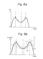
- the bone pattern shown in Fig. 8(a) was obtained from the measurement by densitometry.
- the curve (i) in Fig. 8(a) illustrates the bone pattern obtained by converting the bone width to 10 mm.
- the curve (ii) in Fig. 8(b) illustrates the modified bone pattern obtained by symmetrizing and smoothing the bone pattern, and the curve (iii) in Fig. 8(b) illustrates the bone density distribution.
- the bone densities ( ⁇ ') of the external bone cortex thus obtained are as follows:
Applications Claiming Priority (2)
| Application Number | Priority Date | Filing Date | Title |
|---|---|---|---|
| JP59230077A JPS61109557A (ja) | 1984-11-02 | 1984-11-02 | 骨のx線写真像の評価方法 |
| JP230077/84 | 1984-11-02 |
Publications (2)
| Publication Number | Publication Date |
|---|---|
| EP0180482A2 true EP0180482A2 (fr) | 1986-05-07 |
| EP0180482A3 EP0180482A3 (fr) | 1988-07-20 |
Family
ID=16902184
Family Applications (1)
| Application Number | Title | Priority Date | Filing Date |
|---|---|---|---|
| EP85307943A Ceased EP0180482A3 (fr) | 1984-11-02 | 1985-11-01 | Méthode pour l'évaluation d'os |
Country Status (3)
| Country | Link |
|---|---|
| US (1) | US4721112A (fr) |
| EP (1) | EP0180482A3 (fr) |
| JP (1) | JPS61109557A (fr) |
Cited By (6)
| Publication number | Priority date | Publication date | Assignee | Title |
|---|---|---|---|---|
| US5090040A (en) * | 1989-03-10 | 1992-02-18 | Expert Image Systems, Inc. | Data acquisition system for radiographic imaging |
| EP1036543A1 (fr) * | 1999-03-15 | 2000-09-20 | Samsung SDS Co. Ltd. | Système de traitements de données, méthode et produit de programme informatique |
| EP1237483A1 (fr) * | 1999-12-01 | 2002-09-11 | Ronald E. Massie | Systeme et methode de modelisation en densitometrie dentaire et orthopedique |
| US7839970B2 (en) | 1999-12-01 | 2010-11-23 | Massie Ronald E | Dental and orthopedic densitometry modeling system and method |
| US8073101B2 (en) | 1999-12-01 | 2011-12-06 | Massie Ronald E | Digital modality modeling for medical and dental applications |
| US8126112B2 (en) | 1999-12-01 | 2012-02-28 | Massie Ronald E | Osseo classification system and method |
Families Citing this family (51)
| Publication number | Priority date | Publication date | Assignee | Title |
|---|---|---|---|---|
| DE3687519T2 (de) * | 1985-11-11 | 1993-05-13 | Teijin Ltd | Verfahren zur beurteilung von knochen. |
| ATE152339T1 (de) * | 1989-02-23 | 1997-05-15 | Teijin Ltd | Verfahren zum messen einer knochenform, vorrichtung dafür sowie system zur knochenevaluation |
| US5138553A (en) * | 1989-03-10 | 1992-08-11 | Expert Image Systems, Inc. | Method and apparatus for bone mineral measurement using a measurement region defined at a selected distance from a styloid bone tip |
| JPH03230670A (ja) * | 1990-02-05 | 1991-10-14 | Teijin Ltd | 画像読み取り装置及び骨計測装置 |
| US5509042A (en) * | 1991-02-13 | 1996-04-16 | Lunar Corporation | Automated determination and analysis of bone morphology |
| US5533084A (en) * | 1991-02-13 | 1996-07-02 | Lunar Corporation | Bone densitometer with improved vertebral characterization |
| US5577089A (en) * | 1991-02-13 | 1996-11-19 | Lunar Corporation | Device and method for analysis of bone morphology |
| US5247934A (en) * | 1991-08-09 | 1993-09-28 | Trustees Of The University Of Pennsylvania | Method and apparatus for diagnosing osteoporosis with MR imaging |
| DE69329168T2 (de) * | 1992-05-20 | 2001-04-05 | Aloka Co Ltd | Vorrichtung zur Bestimmung der Eigenschaften von Knochen |
| ATE169808T1 (de) * | 1992-06-04 | 1998-09-15 | Teijin Ltd | Verfahren und gerät zur knochen-messung |
| US5585603A (en) * | 1993-12-23 | 1996-12-17 | Design Systems, Inc. | Method and system for weighing objects using X-rays |
| WO1996007161A1 (fr) * | 1994-08-29 | 1996-03-07 | Eskofot A/S | Procede d'estimation |
| US5673303A (en) * | 1995-04-19 | 1997-09-30 | Wright State University | Method and apparatus for the evaluation of structural width and density by computed tomography |
| US6213934B1 (en) | 1995-06-01 | 2001-04-10 | Hyper3D Corp. | Electromagnetic bone-assessment and treatment: apparatus and method |
| US5782763A (en) * | 1995-06-01 | 1998-07-21 | Cyberlogic Inc. | Electromagnetic bone-assessment apparatus and method |
| US5696805A (en) * | 1996-09-17 | 1997-12-09 | Eastman Kodak Company | Apparatus and method for identifying specific bone regions in digital X-ray images |
| GB9702202D0 (en) * | 1997-02-04 | 1997-03-26 | Osteometer Meditech As | Diagnosis of arthritic conditions |
| JP2002507917A (ja) | 1997-07-04 | 2002-03-12 | トルサナ オステオポロシス ダイアグノスティクス アクティーゼルスカブ | 脊椎動物の骨質又は骨格状態を評価するための方法 |
| US6252928B1 (en) | 1998-01-23 | 2001-06-26 | Guard Inc. | Method and device for estimating bone mineral content of the calcaneus |
| AU2887499A (en) | 1998-03-02 | 1999-09-20 | Image Anaylsis, Inc. | Automated x-ray bone densitometer |
| ATE279145T1 (de) * | 1999-04-20 | 2004-10-15 | Sectra Pronosco As | Vorrichtung zur abschätzung der knochenmineraldichte mittels röntgenbildmessungen |
| EP1121661A1 (fr) * | 1999-05-20 | 2001-08-08 | Torsana Osteoporosis Diagnostics A/S | Procede et dispositif de selection et d'evaluation de substances dans le traitement de maladies osseuses |
| US6711282B1 (en) * | 1999-10-29 | 2004-03-23 | Compumed, Inc. | Method for automatically segmenting a target bone from a digital image |
| US6246745B1 (en) | 1999-10-29 | 2001-06-12 | Compumed, Inc. | Method and apparatus for determining bone mineral density |
| US6510197B1 (en) | 2000-01-11 | 2003-01-21 | Alara, Inc. | Method and apparatus for osteoporosis screening |
| CN1498385A (zh) * | 2000-08-29 | 2004-05-19 | 成像治疗仪公司 | X图像量析的方法与装置 |
| US7467892B2 (en) | 2000-08-29 | 2008-12-23 | Imaging Therapeutics, Inc. | Calibration devices and methods of use thereof |
| US20020186818A1 (en) * | 2000-08-29 | 2002-12-12 | Osteonet, Inc. | System and method for building and manipulating a centralized measurement value database |
| US6904123B2 (en) * | 2000-08-29 | 2005-06-07 | Imaging Therapeutics, Inc. | Methods and devices for quantitative analysis of x-ray images |
| US7660453B2 (en) * | 2000-10-11 | 2010-02-09 | Imaging Therapeutics, Inc. | Methods and devices for analysis of x-ray images |
| US8639009B2 (en) * | 2000-10-11 | 2014-01-28 | Imatx, Inc. | Methods and devices for evaluating and treating a bone condition based on x-ray image analysis |
| EP1389947B1 (fr) | 2001-05-25 | 2009-08-26 | Imaging Therapeutics, Inc. | Procedes pour le diagnostic, le traitement et la prevention de perte osseuse |
| US6990222B2 (en) * | 2001-11-21 | 2006-01-24 | Arnold Ben A | Calibration of tissue densities in computerized tomography |
| US7840247B2 (en) | 2002-09-16 | 2010-11-23 | Imatx, Inc. | Methods of predicting musculoskeletal disease |
| AU2003275184A1 (en) * | 2002-09-16 | 2004-04-30 | Imaging Therapeutics, Inc. | Imaging markers in musculoskeletal disease |
| US8965075B2 (en) | 2002-09-16 | 2015-02-24 | Imatx, Inc. | System and method for predicting future fractures |
| EP1605824A2 (fr) | 2003-03-25 | 2005-12-21 | Imaging Therapeutics, Inc. | Procedes de compensation de technique d'imagerie dans le traitement d'images radiographiques |
| US8290564B2 (en) * | 2003-09-19 | 2012-10-16 | Imatx, Inc. | Method for bone structure prognosis and simulated bone remodeling |
| AU2004274003A1 (en) * | 2003-09-19 | 2005-03-31 | Imaging Therapeutics, Inc. | Method for bone structure prognosis and simulated bone remodeling |
| DE102004033989B4 (de) * | 2004-07-14 | 2015-08-13 | Siemens Aktiengesellschaft | Verfahren zur Messung der dreidimensionalen Dichteverteilung in Knochen |
| EP1789924A2 (fr) | 2004-09-16 | 2007-05-30 | Imaging Therapeutics, Inc. | Systeme et procede de prediction de futures fractures |
| WO2006039358A2 (fr) * | 2004-09-30 | 2006-04-13 | The Regents Of The University Of California | Methode d'evaluation de caracteristiques de structure-fonction de structures dans un corps humain ou animal |
| US7959742B2 (en) * | 2007-07-11 | 2011-06-14 | Whirlpool Corporation | Outer support body for a drawer-type dishwasher |
| US7706501B2 (en) * | 2007-09-07 | 2010-04-27 | Carestream Health, Inc. | Method and apparatus for measuring long bone density of small-animals |
| US20090105775A1 (en) * | 2007-10-19 | 2009-04-23 | David Mitchell | Cannula with lateral access and directional exit port |
| US8597301B2 (en) * | 2007-10-19 | 2013-12-03 | David Mitchell | Cannula with lateral access and directional exit port |
| US8939917B2 (en) * | 2009-02-13 | 2015-01-27 | Imatx, Inc. | Methods and devices for quantitative analysis of bone and cartilage |
| US8280138B2 (en) * | 2009-09-10 | 2012-10-02 | General Electric Company | System and method for performing bone densitometer measurements |
| US11850061B2 (en) | 2013-08-09 | 2023-12-26 | O.N.Diagnostics, LLC | Clinical assessment of fragile bone strength |
| US9848818B1 (en) | 2013-08-09 | 2017-12-26 | O.N.Diagnostics, LLC | Clinical assessment of fragile bone strength |
| WO2016073888A1 (fr) * | 2014-11-06 | 2016-05-12 | Echols Michael Scott | Dispositif de détection de densité radiographique |
Family Cites Families (9)
| Publication number | Priority date | Publication date | Assignee | Title |
|---|---|---|---|---|
| US2898466A (en) * | 1954-03-15 | 1959-08-04 | Halliburton Oil Well Cementing | Density determining device |
| US3180985A (en) * | 1962-05-14 | 1965-04-27 | Electronic Automation Systems | Standardization of radiation-absorption type density gages |
| US3483565A (en) * | 1968-05-21 | 1969-12-09 | Cedars Of Lebanon Mount Sinai | Color adapter for multidetector scanner |
| US3715588A (en) * | 1970-10-26 | 1973-02-06 | Norland Corp | Bone mineral analyzer |
| SE373279B (sv) * | 1973-05-11 | 1975-02-03 | Atomenergi Ab | Forfarande och anordning for undersokning av en del av en biologisk vevnad |
| US3996471A (en) * | 1975-03-11 | 1976-12-07 | Nasa | Method and system for in vivo measurement of bone tissue using a two level energy source |
| US4515165A (en) * | 1980-02-04 | 1985-05-07 | Energy Conversion Devices, Inc. | Apparatus and method for detecting tumors |
| JPS58206719A (ja) * | 1982-05-27 | 1983-12-02 | 帝人株式会社 | X線フィルムにおける像による骨年令評価方法 |
| JPS598935A (ja) * | 1982-07-08 | 1984-01-18 | 帝人株式会社 | X線フィルムにおける像の処理装置 |
-
1984
- 1984-11-02 JP JP59230077A patent/JPS61109557A/ja active Granted
-
1985
- 1985-10-31 US US06/793,387 patent/US4721112A/en not_active Expired - Fee Related
- 1985-11-01 EP EP85307943A patent/EP0180482A3/fr not_active Ceased
Non-Patent Citations (3)
| Title |
|---|
| KOTSU TAISHA, vol. 14, 1981, pages 319-325; H. KUROSE et al.: "The evaluation of bones in children by the röntgenogram-densitometric analysis" * |
| KOTSU TAISHA, vol. 14, 1981, pages 91-104 * |
| PROCEEDINGS OF THE IEEE 1978 NATIONAL AEROSPACE AND ELECTRONICS CONFERENCE, NAECON, Dayton, Ohio, 16th-18th May 1978, vol. 1; pages 393-397, IEEE, New York; J. BAILEY et al.: "Computer-assisted measurement of cortical bone" * |
Cited By (9)
| Publication number | Priority date | Publication date | Assignee | Title |
|---|---|---|---|---|
| US5090040A (en) * | 1989-03-10 | 1992-02-18 | Expert Image Systems, Inc. | Data acquisition system for radiographic imaging |
| EP1036543A1 (fr) * | 1999-03-15 | 2000-09-20 | Samsung SDS Co. Ltd. | Système de traitements de données, méthode et produit de programme informatique |
| US6224373B1 (en) | 1999-03-15 | 2001-05-01 | Samsung Sds Co., Ltd. | Simulation method for visualizing density of jawbone for dental implantation |
| EP1237483A1 (fr) * | 1999-12-01 | 2002-09-11 | Ronald E. Massie | Systeme et methode de modelisation en densitometrie dentaire et orthopedique |
| EP1237483B1 (fr) * | 1999-12-01 | 2008-11-26 | Ronald E. Massie | Systeme de modelisation en densitometrie dentaire et orthopedique |
| US7839970B2 (en) | 1999-12-01 | 2010-11-23 | Massie Ronald E | Dental and orthopedic densitometry modeling system and method |
| US8073101B2 (en) | 1999-12-01 | 2011-12-06 | Massie Ronald E | Digital modality modeling for medical and dental applications |
| US8126112B2 (en) | 1999-12-01 | 2012-02-28 | Massie Ronald E | Osseo classification system and method |
| US8498374B2 (en) | 1999-12-01 | 2013-07-30 | Osseo Imaging, Llc | Dental and orthopedic densitometry modeling system and method |
Also Published As
| Publication number | Publication date |
|---|---|
| US4721112A (en) | 1988-01-26 |
| EP0180482A3 (fr) | 1988-07-20 |
| JPS61109557A (ja) | 1986-05-28 |
| JPH0331061B2 (fr) | 1991-05-02 |
Similar Documents
| Publication | Publication Date | Title |
|---|---|---|
| US4721112A (en) | Bone evaluation method | |
| US4903203A (en) | Bone evaluation method | |
| Bousson et al. | Volumetric quantitative computed tomography of the proximal femur: relationships linking geometric and densitometric variables to bone strength. Role for compact bone | |
| Rüegsegger et al. | Quantification of bone mineralization using computed tomography | |
| Koot et al. | Evaluation of the Singh index for measuring osteoporosis | |
| Zatz et al. | Changes on computed cranial tomography with aging: intracranial fluid volume. | |
| Kelly et al. | Single X-ray absorptiometry of the forearm: precision, correlation, and reference data | |
| Ostlere et al. | Osteoporosis and bone density measurement methods | |
| US5602935A (en) | Bone morphometric method using radiation patterns along measuring lines related to a bone axis and apparatus for carrying out the same | |
| Hagiwara et al. | Quantification of bone mineral content using dual‐photon absorptiometry in a normal Japanese population | |
| Hillmann et al. | Proximal femoral focal deficiency: radiologic analysis of 49 cases. | |
| Farquharson et al. | Measuring bone mineral density in archaeological bone using energy dispersive low angle X-ray scattering techniques | |
| Braillon | Quantitative computed tomography precision and accuracy for long-term follow-up of bone mineral density measurements: a five-year in vitro assessment | |
| US7046834B2 (en) | Method for measuring bone mineral density by using X-ray image | |
| Mazess et al. | A comparison of radiological methods for determining bone mineral content. | |
| Chesnut III | Noninvasive techniques for measuring bone mass: a comparative review | |
| Korstjens et al. | Reliability of an image analysis system for quantifying the radiographic trabecular pattern | |
| Ha et al. | Cross-calibration of bone mineral densities and body composition between GE lunar prodigy and osteosys primus | |
| Trouerbach et al. | Microdensitometric analysis of interdental bone structure; the development of a registration method | |
| DOYLE | Age-related bone changes in women | |
| JPS639461B2 (fr) | ||
| Dickson et al. | THE QUANTITATIVE COLOUR TELEVISION IMAGE ANALYSER: A New Method of Measuring Bone Density | |
| RU2136214C1 (ru) | Способ определения содержания минерального вещества в костной ткани | |
| Edidin | Modeling of bone material properties from CT scans: considerations in biomechanical structural models | |
| JP2812875B2 (ja) | 骨計測方法 |
Legal Events
| Date | Code | Title | Description |
|---|---|---|---|
| PUAI | Public reference made under article 153(3) epc to a published international application that has entered the european phase |
Free format text: ORIGINAL CODE: 0009012 |
|
| AK | Designated contracting states |
Kind code of ref document: A2 Designated state(s): DE FR GB IT |
|
| PUAL | Search report despatched |
Free format text: ORIGINAL CODE: 0009013 |
|
| AK | Designated contracting states |
Kind code of ref document: A3 Designated state(s): DE FR GB IT |
|
| 17P | Request for examination filed |
Effective date: 19880923 |
|
| 17Q | First examination report despatched |
Effective date: 19900903 |
|
| STAA | Information on the status of an ep patent application or granted ep patent |
Free format text: STATUS: THE APPLICATION HAS BEEN REFUSED |
|
| 18R | Application refused |
Effective date: 19930407 |
|
| APAF | Appeal reference modified |
Free format text: ORIGINAL CODE: EPIDOSCREFNE |
|
| RIN1 | Information on inventor provided before grant (corrected) |
Inventor name: HIRANO, YOSHIO Inventor name: UOTANI, YASUHIRO |