EP0180331B1 - Bar code reader and method of measuring bar codes. - Google Patents
Bar code reader and method of measuring bar codes. Download PDFInfo
- Publication number
- EP0180331B1 EP0180331B1 EP85306979A EP85306979A EP0180331B1 EP 0180331 B1 EP0180331 B1 EP 0180331B1 EP 85306979 A EP85306979 A EP 85306979A EP 85306979 A EP85306979 A EP 85306979A EP 0180331 B1 EP0180331 B1 EP 0180331B1
- Authority
- EP
- European Patent Office
- Prior art keywords
- bar
- bar code
- photodetector
- photodetectors
- space
- Prior art date
- Legal status (The legal status is an assumption and is not a legal conclusion. Google has not performed a legal analysis and makes no representation as to the accuracy of the status listed.)
- Expired
Links
Images


Classifications
-
- G—PHYSICS
- G06—COMPUTING OR CALCULATING; COUNTING
- G06K—GRAPHICAL DATA READING; PRESENTATION OF DATA; RECORD CARRIERS; HANDLING RECORD CARRIERS
- G06K7/00—Methods or arrangements for sensing record carriers, e.g. for reading patterns
- G06K7/01—Details
- G06K7/016—Synchronisation of sensing process
- G06K7/0166—Synchronisation of sensing process by means of clock-signals derived from the code marks, e.g. self-clocking code
-
- G—PHYSICS
- G06—COMPUTING OR CALCULATING; COUNTING
- G06K—GRAPHICAL DATA READING; PRESENTATION OF DATA; RECORD CARRIERS; HANDLING RECORD CARRIERS
- G06K7/00—Methods or arrangements for sensing record carriers, e.g. for reading patterns
- G06K7/10—Methods or arrangements for sensing record carriers, e.g. for reading patterns by electromagnetic radiation, e.g. optical sensing; by corpuscular radiation
- G06K7/14—Methods or arrangements for sensing record carriers, e.g. for reading patterns by electromagnetic radiation, e.g. optical sensing; by corpuscular radiation using light without selection of wavelength, e.g. sensing reflected white light
Definitions
- the present invention relates generally to the art of bar code scanning, and more particularly to apparatuses for measuring absolute spatial distances of bars and spaces within bar codes, and to a method for determining a precise absolute distance of the widths of bars and spaces.
- apparatuses for measuring relative widths or distances of bar codes having a light source and a photodetector for detecting light reflected from a light source off a label or sheet having a bar code imprinted thereon.
- Such apparatuses require either portability so that the light source and detector, together with some related circuitry can be passed over a bar code imprint, or movement of the bar code imprint past the light source and detector circuit. Such movement is designed to be made by a human holding either the bar code detecting circuitry or holding the bar code imprint.
- Such scanning apparatuses are used primarily for verifying the accuracy of the bar code imprint, in order to determine whether the bar code when read by standard bar code readers as, for example, grocers and retail stores will produce the correct billing and identification information in the bar code readers.
- bar code measuring apparatus that will measure the absolute spatial distances or widths or bars and spaces in bar codes without relying on relative and proportional widths of the bars and the spaces to each other. It is also desired to have bar code measuring apparatuses that can make absolute spatial measurements of the widths or distances of bars and spaces, which are portable and operable by a human holding such apparatuses. It is desired, further, to have a bar code measuring apparatus that is capable of establishing or having established its own fixed and predetermined spatial reference distance against which the widths or distances of bars and spaces in the bar code can be absolutely and precisely measured.
- a bar code measuring apparatus comprising a central digital processing unit for processing digital signals, and including a digital clock or constant frequency pulse generator and digital memory means for determining precise spatial distance measurements on the basis of sensed light and dark areas, that is, spaces and bars in a bar code.
- An integral unit has a light source and two optical photodetectors positioned to receive light reflected off a surface outside the integral unit.
- the photodetectors are spaced a fixed and a predetermined distance from each other, and connected by independent and parallel circuits to the central processing unit after providing a digital signal in response to a change in the reflectivity of the outside surface.
- the photodetectors will detect reflected light from a single point at different times, which are carefully measured against the pulse generator.
- the light reflected from the light source is magnified by a factor of five in a magnifying lens in order to amplify the spatial distance image created at the point where the photodetectors are mounted.
- the central processing unit determines the velocity of the measuring apparatus over the detected surface, such as the leading edge of the bar or space, by computing the dividend of the fixed distance between the photodetectors and the absolute time as measured against the pulse generator. A second velocity is similarly determined at the trailing edge of either the bar or the space in a bar code. An average of these velocities is used as the multiplier with the time of one or the other of the photodetectors passing over the bar or the space to provide as quotient the precise and absolute distance of the width of bar or the space.
- a method for determining the absolute spatial distance of individual bars and spaces in a bar code having a plurality of bars and spaces in sequential position having the steps of passing over the bar code from a beginning progressively to an end of the bar code, first and second photodetectors having between them a fixed and predetermined distance in the direction of scan, each photodetector receiving light reflected off the bar code from a common source or sources. Since the bar code has a distance between eath other that is fixed and precisely measureable, the velocity of the photodetectors in the scanner can be determined if the time between the time that the first photodetector senses points on the bar code, and the time the second photodetector sense the same points on the bar code can be determined.
- Such times can be determined when the instance of the sensing by the photodetector of a certain point is measured against an absolute, e.g., digital clock, such as a constant frequency pulse generator and, the instance the second photodetector senses the same point at a later time can be measured against the same constant frequency pulse generator. The number of pulses between the two times can be counted. From these absolute references, the absolute distance between sensed points on the bar code is shown and described to be determinable.
- an absolute e.g., digital clock
- a bar code measuring apparatus has those features set out in Claim 1.
- a method for determining the width of bars and spaces therebetween in a bar code having a plurality of bars and spaces in sequential position having a beginning and an end is characterised by those features set out in Claim 6.
- a measuring device 10 is shown, reference being had initially to Figures 1 and 2 of the drawings.
- the measuring device is enclosed within a cabinet 12 having a window 14 through which the alphanumeric display can be viewed.
- Indicator lights 16 protrude through the cabinet 12 so as to be seen from the outside.
- the optical measuring device 10 comprises initially a light circuit beginning with a set of light sources 20 directing a relatively high intensity of lumens through an aperture 22, best seen in Figure 2.
- the light is reflected off or from a surface below the aperture 22 containing, for example, a bar code having a row of dark lines of varying widths separated by spaces of varying widths.
- distance or width
- the leading edge of a bar of a space will be that substantially vertical edge over which the light from the light sources 20 of the measuring device 10 passes first.
- the trailing edge of a bar or of a space will be that substantially vertical edge over which the light from the light source 20 of the measuring device 10 passes after the leading edge.
- the light sources are passed over a bar code comprising rows of vertically parallel dark or low-reflectivity bars, and light or high-reflectivity spaces, in a horizontal direction and usually from left to right.
- practice of the invention described herein will also result in precise and accurate distance measurements of the widths of the bars and the spaces when passing the light sources 20 from right to left.
- Light reflected off the bar code imprint surface returns through the aperture 22 into a lens 28 along a light path 30.
- An access hole 26 through an optical block 24 allows for the insertion of an adjusting tool for engaging an annular depression in the lens 28 for adjusting the position of the lens vertically along the light path 30, should such measurement be necessary.
- the lens 28 is mounted within the optical block 24 which is mounted on the cabinet 12 and frame of the measuring device 10, but not so tightly that it cannot be adjusted vertically.
- a mirror 32 positioned at a 45 o angle to the light path 30 directs the light in a right angle turn from the lens 28 through an aperture 33 and an aperture 34 in a light box 38.
- the aperture 34 has a flair outwardly in the direction of light path 30 for reducing the flare of the light as it travels along the path 30.
- the light box 38 is constructed preferably of light absorbing, black material, again for the purpose of reducing the flare of the light along the path 30.
- the light path 30 terminates on a holder 36 holding the photodetectors shown schematically in the block diagram of Figure 3, and in more detail in the electrical schematic diagram of Figure 4.
- Various parts of the electrical circuitry are mounted on circuit boards 40 within the cabinet 12, the circuit schematics being explained in greater detail below.
- circuit boards 40 within the cabinet 12, the circuit schematics being explained in greater detail below.
- various components are shown generally mounted on the boards 40 solely for the purpose of indicating a preferred method of housing the physical elements of the circuit elements.
- a light source assembly 50 having the light source 20 ( Figures 1 and 2) directing light toward photodetectors 44, 48, and also directing light to an internal detector 51. Light is detected by the internal detector 51 which is mounted in close proximity to the light source 20.
- the light source 20 is comprised of a light emitting diode (LED) and the detector is a photodetecting diode 51 mounted in a feedback loop to an amplifier 52 for inversely regulating the current through the light source 20, so that as the light from the light source increases, the feedback loop including the detector 51 will decrease the current through the LED and hence decrease the intensity of the light output. In this manner, the light output of the LED is maintained at a stable and constant level.
- the electrical circuit of the light assembly 50 is shown in greater detail in Figure 4 of the drawings.
- each photodetector 44, 48 is the beginning of a separate photometric channel operating in parallel to each other.
- Light impending on one of the photodetectors 44, 48 is converted into an analogue electrical signal, is amplified in an analogue amplifier 56, 66 and is then converted to a digital form in an analogue-to-digital converter and analogue comparator 58, 68.
- the signal then passes to an edge detector 60, 70 which comprises an electrical circuit for generating a pulse whenever the digital signal of the converter 58, 68 goes from a high to a low, or from a low to a high across a threshold level signifying the sensing of an edge of a bar or a space in the bar code.
- the pulse from the edge detector 60, 70 is seen respectively at a latch 62, 72 which latches the then present counter value from a counter 74.
- a constant frequency pulse generator 64 generates a clock pulse which constantly updates the counter 74. Pulses from the generator 64 are also used to synchronize the latch 62, 72 with the counter 74 to prevent erroneous data from being loaded into the latch 62, 72.
- a central processing unit 76 is connected to the latches 62, 72 to selectively receive digital signal information therefrom and to determine the spatial distance measuring the width dimension of the bars and spaces, as will be explained in greater detail below.
- a display and control assembly 78 controls the display seen through the window 14 ( Figure 1).
- the photodetectors 44, 48 comprise light sensitive diodes which increase current with the increase in light detected.
- the diode 44 is connected to the analogue amplifier circuit 56 which converts the current signal to a voltage signal in an operational amplifier 80, and amplifies the voltage signal in an amplifier 82 producing an analogue voltage signal at an output 84 to the analogue-to-digital converter 58.
- the photodetector diode 48 increases current with the increase of sensed or detected light, and the increased current is output to the analogue amplifier 66, shown in broken lines in Figure 5.
- the current signal is converted by an operational amplifier 88 to an analogue voltage signal which is amplified by an amplifier 90 and directed by an output 92 to the analogue-to-digital converter 68.
- a latch 96 which could be, for example, a TTL174, resets the counter of the converter-comparator 58, 68 which could be, for example, a TL507.
- the latch 96 controls the operations of the converter-comparator 58, 68 to compare the analogue voltage signal against a predetermined threshold determined by the mean of the highest and the lowest analogue voltage signal seen at the converter-comparator during the reflective measurement phase of the bar code scanning cycle.
- the analogue signal crosses the threshold value in the comparator 58, 68, the output along a connector 100, 102 is changed, resulting in a change in an output 104, 106 of the edge detectors 60, 70 as seen better in the detailed electrical schematic diagram of Figure 6.
- the edge detector 60, 70 receives the output of the converter-comparator 58, 68 and is stored in the low order position of the latch 62, 72.
- the counter 74 is also latched into the latch 62, 72 when the transition or signal of the leads 104, 106 occur.
- the clock pulse is seen in a lead 65 and is generated by a constant frequency pulse generating circuit 64 (seen in greater detail in Figure 7).
- a frequency generator 110 produces a 6 megahertz pulse frequency, which is divided by three in a divider 112 and divided by two in a divider 114.
- a flip-flop 116 generates two non-overlapping square waves 180 o out of phase, as required by the central processor 76 which, in the preferred embodiment, is a Motorola 6800.
- the clock frequency therefore, is 1 MHz. in the lead 64.
- the central processing unit 76 is seen in greater detail in Figure 7 of the drawings and comprises a Motorola 6800 processor connected with three 4K by 8 bit, read only memories (ROMs) and one 2K by 8 bit random access memory (RAM).
- ROMs read only memories
- RAM random access memory
- a peripheral, interconnect or interface adaptor 132 is connected to a common microprocessor bus 130, common to Figures 6, 7 and 8.
- a re-set switch 134 is provided to re-start the processor 76.
- a function switch 136 is also provided for serially stepping through the data generated by the analysis of the bar code scanned by the measuring device 10.
- An audible indicator 138 and light indicators, such as LED's 140 can be provided for giving certain signals in accordance with the program of the ROMs 122.
- An alphanumeric display 144 is connected to the interface 132 to provide visual displays of the data determined by the analysis of the program in ROM's 122.
- the alphanumeric displays can be seen through the window 14 provided in the cabinet 12 ( Figure 1).
- a hypothical bar code has bars 160, 162, 164 having varying widths or distances of, respectively, 0.010 inch (0.25mm), 0.0075 inch (0.19mm) and 0.015 inch (0.38mm), (not actual size in the drawing of Figure 9 but drawn to a scale of 100:1).
- the bars, as well as the spaces 161, 163 therebetween are aligned vertically and parallel to each other.
- Each bar and each space has a leading edge and a trailing edge in the horizontal direction.
- the bar 160 has a leading edge 166 and a trailing edge 168.
- the trailing edge 168 is the leading edge for the space 161.
- a trailing edge 170 for the space 161 comprises the leading edge for the bar 162.
- a trailing edge 172 for the bar 162 comprises the leading edge for the space 163.
- a trailing edge 174 for the space 163 comprises the leading edge for the bar 164.
- the detectors 44, 48 receive light through the magnifying lens 28, so that the image at the detectors 44, 48 simulates a fixed and predetermined distance between the detectors 44, 48 of 0.010 inch (0.25mm).
- the image of each detector simulates a detector having a surface area of 0.02 inch (0.5mm) by 0.002 inch (0.05mm), as indicated in the diagram of Figure 9.
- the wave forms 184, 186 of Row 1 are the signals as seen in the output 84, 92, respectively, between the analogue amplifiers 56, 66 and the converters-comparators 58, 68, ( Figures 3 and 5 of the drawings).
- Row 2 represents the wave form of the digital outputs 100, 102, respectively, the photometric channels 1 of photodetectors 44, and 2 of photodetectors 48. These output signals can be seen in Figures 3, 5 and 6 of the drawings.
- Row 3 of Figure 9 is a representation of the time that the respective photometric channels had light sensing below the threshold 188 shown in Row 1.
- the times of photometric channel 1 initiated by photodetector 44 are shown in the top Row entitled "Time 1”
- the times of the photometric channel 2 initiated by photodetector 48 are shown in the lower Row entitled “Time 2.”
- the times are determined by a difference in the leading edge and the trailing edge latched into latch 62, 72, respectively, as seen in Figure 3 of the drawings. It will be noted that these times do not map exactly onto the spacings of the bars, because of variations in the scanning velocity. In order to allow for velocity variations, the scanning velocity needs to be determined.
- the time can be measured absolutely by means of the constant frequency pulse generator, and may be taken as the time delay between the passing of the two sensors over the same point.
- the distance D o is known to be the spacing 0.010 inches (0.25mm) between the images of the photodetectors 44, 48.
- the velocity V o can thus be determined.
- x (T4 - T2 + (T3 - T1)(D o /(T2 - T1) + D o /(T4 - T3)))/4
- x the distance across a bar or space
- D o the fixed and predetermined distance between the first photodetector 44 and the second photodetector 48
- T1 the time that the first photodetector 44 crosses the leading edge of the bar or space
- T2 equals the time that the second photodetector 44 crosses the leading edge of the bar space
- T3 equals the time that the first photodetector 44 crosses the trailing edge of the bar or space
- T4 equals the time that the second photodetector 48 crosses the trailing edge of the bar or space.
- a method for determining the spatial distance of individual bars and spaces in a bar code having a plurality of bars and spaces in sequential position is described. Further, a spatial distance measuring apparatus for measuring bar codes, having two photodetectors in fixed and predetermined distance relationship to each other is shown and described wherein the distance or width dimension of each bar and each space of a bar code can be precisely determined regardless of the velocity of the measuring apparatus over the bar code. Further, variations of the velocity inevitable in a human passing the apparatus over the code can be minimized by use of the described apparatus and method.
Landscapes
- Engineering & Computer Science (AREA)
- Physics & Mathematics (AREA)
- Artificial Intelligence (AREA)
- Computer Vision & Pattern Recognition (AREA)
- General Physics & Mathematics (AREA)
- Theoretical Computer Science (AREA)
- Health & Medical Sciences (AREA)
- Electromagnetism (AREA)
- General Health & Medical Sciences (AREA)
- Toxicology (AREA)
- Length Measuring Devices By Optical Means (AREA)
Description
- The present invention relates generally to the art of bar code scanning, and more particularly to apparatuses for measuring absolute spatial distances of bars and spaces within bar codes, and to a method for determining a precise absolute distance of the widths of bars and spaces.
- In the past, apparatuses for measuring relative widths or distances of bar codes have been provided having a light source and a photodetector for detecting light reflected from a light source off a label or sheet having a bar code imprinted thereon. Such apparatuses require either portability so that the light source and detector, together with some related circuitry can be passed over a bar code imprint, or movement of the bar code imprint past the light source and detector circuit. Such movement is designed to be made by a human holding either the bar code detecting circuitry or holding the bar code imprint. Such scanning apparatuses are used primarily for verifying the accuracy of the bar code imprint, in order to determine whether the bar code when read by standard bar code readers as, for example, grocers and retail stores will produce the correct billing and identification information in the bar code readers.
- In making such a check on the bar code, apparatuses in the past have had to make certain assumptions. For example, in digital processing of the information sensed by the photodetector, it is normally assumed that the velocity of the passing of the scanner over the bar code, or vice versa as the case may be, is a constant velocity from the beginning of the bar code to the end of the bar code. Such assmptions may not be valid for relatively wide bars or wide spaces in the bar code. Moreover, most bar codes have sufficient width so that the slightest distraction by the person holding the bar code scanner or the bar code imprint will cause a variation in the velocity, and hence inaccurate readings in the readout or output of the scanning circuitry.
- Moreover, such measurements necessarily are not absolute, but measure the relative distances of the width of the bars and the spaces to each other or to some standard reference. In the past, it has been necessary to have relatively large tolerances in the width of the bars and the spaces in order to accommodate the foreseeable inaccuracies in measuring such widths or distances by handheld scanning devices and photodetectors. The necessity for incorporating such tolerances within reading devices has necessarily limited the precision and the quantity of information that can be stored in bar code imprints in given widths or distances.
- An exemplary scanner is illustrated in IBM Technical Disclosure Bulletin,
Volume 15, No. 6, November 1972, pages 1816-17, J B Davis et al., entitled "Velocity Calibrating Scanner". The scanner shown in this document has the features set out in the pre-characterising portions of the independent claims. - It is desirable to have a bar code measuring apparatus that will measure the absolute spatial distances or widths or bars and spaces in bar codes without relying on relative and proportional widths of the bars and the spaces to each other. It is also desired to have bar code measuring apparatuses that can make absolute spatial measurements of the widths or distances of bars and spaces, which are portable and operable by a human holding such apparatuses. It is desired, further, to have a bar code measuring apparatus that is capable of establishing or having established its own fixed and predetermined spatial reference distance against which the widths or distances of bars and spaces in the bar code can be absolutely and precisely measured. It is desired yet further to have a method for precisely determining the absolute spatial distance or width of bars and spaces in a bar code which does not rely on additional equipment for providing known velocities in the passing of a bar code over a scanner, or of passing a bar code measuring apparatus or scanner over a bar code.
- In brief, a bar code measuring apparatus is described comprising a central digital processing unit for processing digital signals, and including a digital clock or constant frequency pulse generator and digital memory means for determining precise spatial distance measurements on the basis of sensed light and dark areas, that is, spaces and bars in a bar code. An integral unit has a light source and two optical photodetectors positioned to receive light reflected off a surface outside the integral unit. The photodetectors are spaced a fixed and a predetermined distance from each other, and connected by independent and parallel circuits to the central processing unit after providing a digital signal in response to a change in the reflectivity of the outside surface. The photodetectors will detect reflected light from a single point at different times, which are carefully measured against the pulse generator. The light reflected from the light source is magnified by a factor of five in a magnifying lens in order to amplify the spatial distance image created at the point where the photodetectors are mounted.
- The central processing unit in accordance with the structure and program of the processing circuitry, determines the velocity of the measuring apparatus over the detected surface, such as the leading edge of the bar or space, by computing the dividend of the fixed distance between the photodetectors and the absolute time as measured against the pulse generator. A second velocity is similarly determined at the trailing edge of either the bar or the space in a bar code. An average of these velocities is used as the multiplier with the time of one or the other of the photodetectors passing over the bar or the space to provide as quotient the precise and absolute distance of the width of bar or the space.
- A method for determining the absolute spatial distance of individual bars and spaces in a bar code having a plurality of bars and spaces in sequential position is described having the steps of passing over the bar code from a beginning progressively to an end of the bar code, first and second photodetectors having between them a fixed and predetermined distance in the direction of scan, each photodetector receiving light reflected off the bar code from a common source or sources. Since the bar code has a distance between eath other that is fixed and precisely measureable, the velocity of the photodetectors in the scanner can be determined if the time between the time that the first photodetector senses points on the bar code, and the time the second photodetector sense the same points on the bar code can be determined. Such times can be determined when the instance of the sensing by the photodetector of a certain point is measured against an absolute, e.g., digital clock, such as a constant frequency pulse generator and, the instance the second photodetector senses the same point at a later time can be measured against the same constant frequency pulse generator. The number of pulses between the two times can be counted. From these absolute references, the absolute distance between sensed points on the bar code is shown and described to be determinable.
- According to a first aspect of the invention a bar code measuring apparatus has those features set out in
Claim 1. - According to a second aspect, a method for determining the width of bars and spaces therebetween in a bar code having a plurality of bars and spaces in sequential position having a beginning and an end, is characterised by those features set out in
Claim 6. - The invention may be carried into practice in various ways and one bar code scanner, and its method of operation, will now be described, by way of example, with reference to the diagrams, in which:
- Figure 1 is a perspective view of a measuring apparatus of an embodiment of the present invention, having portions cut away for clarity and understanding;
- Figure 2 is a longitudinal section through the embodiment of Figure 1;
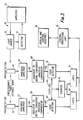
- Figure 3 is a block schematic diagram showing the elemental components of the circuitry of the embodiment of Figure 1;
- Figure 4 is a detailed electrical schematic diagram of the light assembly;
- Figure 5 is a detailed electrical schematic diagram of the independent channels of Figure 3;
- Figure 6 is a detailed electrical schematic diagram of the frequency generator and central processing unit;
- Figure 7 is a detailed electrical schematic diagram of the frequency generator and central processing unit;
- Figure 8 is a detailed electrical schematic diagram of the display and control assembly of Figure 3; and
- Figure 9 is a diagram illustrating certain aspects of the method of the present invention.
- A
measuring device 10 is shown, reference being had initially to Figures 1 and 2 of the drawings. The measuring device is enclosed within acabinet 12 having awindow 14 through which the alphanumeric display can be viewed.Indicator lights 16 protrude through thecabinet 12 so as to be seen from the outside. - The
optical measuring device 10 comprises initially a light circuit beginning with a set oflight sources 20 directing a relatively high intensity of lumens through anaperture 22, best seen in Figure 2. The light is reflected off or from a surface below theaperture 22 containing, for example, a bar code having a row of dark lines of varying widths separated by spaces of varying widths. In this specification, and in the appended claims the term distance (or width) will be used to indicate the dimension separating the leading edge and the trailing edge of bars and of spaces. The leading edge of a bar of a space will be that substantially vertical edge over which the light from thelight sources 20 of themeasuring device 10 passes first. The trailing edge of a bar or of a space will be that substantially vertical edge over which the light from thelight source 20 of themeasuring device 10 passes after the leading edge. Normally, the light sources are passed over a bar code comprising rows of vertically parallel dark or low-reflectivity bars, and light or high-reflectivity spaces, in a horizontal direction and usually from left to right. However, practice of the invention described herein will also result in precise and accurate distance measurements of the widths of the bars and the spaces when passing thelight sources 20 from right to left. - Light reflected off the bar code imprint surface returns through the
aperture 22 into alens 28 along alight path 30. Anaccess hole 26 through anoptical block 24 allows for the insertion of an adjusting tool for engaging an annular depression in thelens 28 for adjusting the position of the lens vertically along thelight path 30, should such measurement be necessary. Thelens 28 is mounted within theoptical block 24 which is mounted on thecabinet 12 and frame of themeasuring device 10, but not so tightly that it cannot be adjusted vertically. - A
mirror 32 positioned at a 45o angle to thelight path 30 directs the light in a right angle turn from thelens 28 through anaperture 33 and anaperture 34 in alight box 38. Theaperture 34 has a flair outwardly in the direction oflight path 30 for reducing the flare of the light as it travels along thepath 30. - The
light box 38 is constructed preferably of light absorbing, black material, again for the purpose of reducing the flare of the light along thepath 30. Thelight path 30 terminates on aholder 36 holding the photodetectors shown schematically in the block diagram of Figure 3, and in more detail in the electrical schematic diagram of Figure 4. Various parts of the electrical circuitry are mounted oncircuit boards 40 within thecabinet 12, the circuit schematics being explained in greater detail below. In Figures 1 and 2, various components are shown generally mounted on theboards 40 solely for the purpose of indicating a preferred method of housing the physical elements of the circuit elements. - Referring now to Figures 3 and 4 of the drawings, a
light source assembly 50 is shown having the light source 20 (Figures 1 and 2) directing light towardphotodetectors internal detector 51. Light is detected by theinternal detector 51 which is mounted in close proximity to thelight source 20. Thelight source 20 is comprised of a light emitting diode (LED) and the detector is a photodetectingdiode 51 mounted in a feedback loop to anamplifier 52 for inversely regulating the current through thelight source 20, so that as the light from the light source increases, the feedback loop including thedetector 51 will decrease the current through the LED and hence decrease the intensity of the light output. In this manner, the light output of the LED is maintained at a stable and constant level. The electrical circuit of thelight assembly 50 is shown in greater detail in Figure 4 of the drawings. - Referring now in more detail to Figure 3 of the drawings, the
photodetectors photodetector photodetectors analogue amplifier analogue comparator edge detector converter - The pulse from the
edge detector latch counter 74. A constantfrequency pulse generator 64 generates a clock pulse which constantly updates thecounter 74. Pulses from thegenerator 64 are also used to synchronize thelatch counter 74 to prevent erroneous data from being loaded into thelatch central processing unit 76 is connected to thelatches assembly 78 controls the display seen through the window 14 (Figure 1). - Referring now to Figure 5 of the drawings, the individual electrical components of a portion of the block schematic diagram of Figure 3 can be seen in greater detail. Thus, the
photodetectors diode 44 is connected to theanalogue amplifier circuit 56 which converts the current signal to a voltage signal in anoperational amplifier 80, and amplifies the voltage signal in anamplifier 82 producing an analogue voltage signal at anoutput 84 to the analogue-to-digital converter 58. - Similarly, the
photodetector diode 48 increases current with the increase of sensed or detected light, and the increased current is output to theanalogue amplifier 66, shown in broken lines in Figure 5. The current signal is converted by anoperational amplifier 88 to an analogue voltage signal which is amplified by anamplifier 90 and directed by anoutput 92 to the analogue-to-digital converter 68. - A
latch 96, which could be, for example, a TTL174, resets the counter of the converter-comparator latch 96 controls the operations of the converter-comparator comparator connector output edge detectors - In Figure 6 of the drawings, the
edge detector comparator latch counter 74 is also latched into thelatch leads lead 65 and is generated by a constant frequency pulse generating circuit 64 (seen in greater detail in Figure 7). - Referring to figure 7, a
frequency generator 110 produces a 6 megahertz pulse frequency, which is divided by three in adivider 112 and divided by two in adivider 114. A flip-flop 116 generates two non-overlappingsquare waves 180o out of phase, as required by thecentral processor 76 which, in the preferred embodiment, is a Motorola 6800. The clock frequency, therefore, is 1 MHz. in thelead 64. - The
central processing unit 76 is seen in greater detail in Figure 7 of the drawings and comprises a Motorola 6800 processor connected with three 4K by 8 bit, read only memories (ROMs) and one 2K by 8 bit random access memory (RAM). - In Figure 8, a peripheral, interconnect or
interface adaptor 132 is connected to acommon microprocessor bus 130, common to Figures 6, 7 and 8. Are-set switch 134 is provided to re-start theprocessor 76. Afunction switch 136 is also provided for serially stepping through the data generated by the analysis of the bar code scanned by the measuringdevice 10. Anaudible indicator 138 and light indicators, such as LED's 140 can be provided for giving certain signals in accordance with the program of theROMs 122. - An
alphanumeric display 144 is connected to theinterface 132 to provide visual displays of the data determined by the analysis of the program in ROM's 122. The alphanumeric displays can be seen through thewindow 14 provided in the cabinet 12 (Figure 1). - In operation, reference now being had to Figure 9 of the drawings, a hypothical bar code has
bars spaces bar 160 has aleading edge 166 and a trailingedge 168. The trailingedge 168 is the leading edge for thespace 161. A trailingedge 170 for thespace 161 comprises the leading edge for thebar 162. A trailingedge 172 for thebar 162 comprises the leading edge for thespace 163. A trailingedge 174 for thespace 163 comprises the leading edge for thebar 164. And there is a trailingedge 176 for thebar 164, and so on. To the left of the bar code are shown thephotodetectors detectors lens 28, so that the image at thedetectors detectors - Aligned vertically in the drawing of Figure 9 with the bars and spaces of the bar code are several output signal waveforms in Row 1-4. As the
photodetectors scan direction 180, the darkness of low reflectivity of thebar 160 will initially cause the current in thedetector 44 to decrease significantly, as indicated by line or wave 182 in the waveform shown inRow 1 of the signal waveforms of Figure 9. At precisely 0.010 inches (0.25mm) thereafter, the reflected light sensed by thephotodetector 48, positioned 0.010 inches (0.25mm) behindphotodetector 44 in the direction ofscan 180, also has a significant reduction in its sensed light as indicated by thewave 186 inRow 1. As thephotodetector 44 passes over the the trailingedge 168 of thefirst bar 160, the amount of reflected light sensed increases significantly, and so forth as is shown inRow 1. The wave forms 184, 186 ofRow 1 are the signals as seen in theoutput analogue amplifiers comparators -
Row 2 represents the wave form of thedigital outputs photometric channels 1 ofphotodetectors photodetectors 48. These output signals can be seen in Figures 3, 5 and 6 of the drawings. -
Row 3 of Figure 9 is a representation of the time that the respective photometric channels had light sensing below thethreshold 188 shown inRow 1. The times ofphotometric channel 1 initiated byphotodetector 44 are shown in the top Row entitled "Time 1," and the times of thephotometric channel 2 initiated byphotodetector 48 are shown in the lower Row entitled "Time 2." The times are determined by a difference in the leading edge and the trailing edge latched intolatch Row 4. The velocity at any given time can be calculated from the formula

where Do equals distance, Vo equals velocity and To equals the time. The time can be measured absolutely by means of the constant frequency pulse generator, and may be taken as the time delay between the passing of the two sensors over the same point. The distance Do is known to be the spacing 0.010 inches (0.25mm) between the images of thephotodetectors

- As may be imagined, when moving the photodetectors over the bar code by a human hand, variations in the actual velocity may occur. A calculation designed to minimize variations in velocity, i.e., acceleration, would be to use as the velocity an average of the velocity of the two detectors over the leading edge of each bar and space, and the velocity of the two detectors over the trailing edge of each bar or space. A calculation for the distance using as the velocity this average velocity is given by the equation:

Where x equals the distance across a bar or space, Do equals the fixed and predetermined distance between thefirst photodetector 44 and thesecond photodetector 48,
T₁ equals the time that thefirst photodetector 44 crosses the leading edge of the bar or space,
T₂ equals the time that thesecond photodetector 44 crosses the leading edge of the bar space,
T₃ equals the time that thefirst photodetector 44 crosses the trailing edge of the bar or space, and
T₄ equals the time that thesecond photodetector 48 crosses the trailing edge of the bar or space. - As may be appreciated from the foregoing description of the preferred embodiment, a method for determining the spatial distance of individual bars and spaces in a bar code having a plurality of bars and spaces in sequential position is described. Further, a spatial distance measuring apparatus for measuring bar codes, having two photodetectors in fixed and predetermined distance relationship to each other is shown and described wherein the distance or width dimension of each bar and each space of a bar code can be precisely determined regardless of the velocity of the measuring apparatus over the bar code. Further, variations of the velocity inevitable in a human passing the apparatus over the code can be minimized by use of the described apparatus and method.
Claims (9)
- A bar code measuring apparatus (10) having a first photodetector (44) receiving reflected light from a first point as the first photodetector is passed over bars and spaces, a second photodetector (48) spaced from the first photodetector (44) and receiving reflected light from a second point spaced from the first point by a distance Do; means (58, 60) for producing first and second digital values representative of the times (T₁, T₂) that the first and second photodetectors respectively pass over the leading edge of a bar or space; characterised by digital storage means for storing the first and second digital values; means (68, 70) for producing third and fourth digital values representative of the times (T₃, T₄) that the first and second photodetectors respectively pass over the trailing edge of the bar or space, the second digital values also being stored in the storage means; and digital processing means (76) for determining from the first, second, third and fourth values, given the distance Do, an absolute measurement of the width of the bar or space.
- A bar code measuring apparatus (10) as claimed in Claim 1 in which the means for producing the digital values includes a constant-frequency pulse generator (110), and counting means (116) connected to the constant-frequency pulse generator, the producing means being arranged to produce the first, second, third and fourth digital values by counting pulses between variations in output signals produced by the photodetectors (44, 48).
- A bar code measuring apparatus as claimed in Claim 1 or Claim 2, in which the digital processing means (76) further includes means for determining a velocity from the first, second, third and fourth values.
- A bar code measuring apparatus as claimed in Claim 3 in which the digital processing means (76) includes means for determining a first velocity at which the first (44) and the second (48) photodetectors pass the leading edge, and for determining a second velocity at which the first and the second photodetectors pass the trailing edge.
- A bar code measuring apparatus as claimed in Claim 4 in which the digital processing means (76) includes means for determining the width of the bar or space on the basis of the average of the first and second velocities.
- A method for determining the width of bars and spaces therebetween in a bar code having a plurality of bars and spaces in sequential position having a beginning and an end, comprising:(a) passing over the bar code from the beginning progressively to the end a first photodetector (44) detecting light reflected from each bar and each space;(b) passing over the bar code from the beginning progressively to the end a second photodetector (48) detecting light reflected from each bar and each space at a point spaced a fixed distance (Do) from the point from which the first photodetector (44) detected reflected light;(c) producing first and second digital values representative of the times (T₁, T₂) that the first and second photodetectors respectively pass over the leading edge of a bar or space; characterised by;(d) producing third and fourth digital values representative of the times (T₃, T₄) that the first and second photodetectors respectively pass over the trailing edge of the bar or space; and(e) determining from the first, second, third and fourth values, and the fixed distance (Do), an absolute measurement of the width of the bar or space.
- A method as claimed in Claim 6 including determining a first velocity at which the first (44) and the second (48) photodetectors pass the leading edge and determining a second velocity at which the first (44) and the second (48) photodetectors pass the trailing edge.
- A method as claimed in Claim 7 in which the width of the bar or space is determined on the basis of the average of the first and second velocities.
- A method as claimed in any one of Claims 6 to 8 in which output signals representative of the first photodetector (44) and of the second photodetector (48) passing over the leading edge are stored in a digital memory against clocked times and a velocity of the photodetectors passing over the leading edge is determined therefrom, and signals representative of the first photodetector (44) and the second photodetector (48) passing over the succeeding trailing edge are stored against clocked times and a velocity of the photodetectors passing over the trailing edge is determined therefrom.
Applications Claiming Priority (2)
| Application Number | Priority Date | Filing Date | Title |
|---|---|---|---|
| US06/655,535 US4705939A (en) | 1984-09-28 | 1984-09-28 | Apparatus and method for optically measuring bar code dimensions |
| US655535 | 1984-09-28 |
Publications (3)
| Publication Number | Publication Date |
|---|---|
| EP0180331A2 EP0180331A2 (en) | 1986-05-07 |
| EP0180331A3 EP0180331A3 (en) | 1988-05-25 |
| EP0180331B1 true EP0180331B1 (en) | 1992-05-13 |
Family
ID=24629275
Family Applications (1)
| Application Number | Title | Priority Date | Filing Date |
|---|---|---|---|
| EP85306979A Expired EP0180331B1 (en) | 1984-09-28 | 1985-09-30 | Bar code reader and method of measuring bar codes. |
Country Status (4)
| Country | Link |
|---|---|
| US (1) | US4705939A (en) |
| EP (1) | EP0180331B1 (en) |
| JP (1) | JPS61190674A (en) |
| DE (1) | DE3586034D1 (en) |
Families Citing this family (39)
| Publication number | Priority date | Publication date | Assignee | Title |
|---|---|---|---|---|
| US5675137A (en) * | 1986-04-18 | 1997-10-07 | Cias, Inc. | Bar code decoding using moving averages to break the (n,k) code barrier for UPC, EAN Code 128 and others |
| US5621203A (en) * | 1992-09-25 | 1997-04-15 | Symbol Technologies | Method and apparatus for reading two-dimensional bar code symbols with an elongated laser line |
| JPH02287779A (en) * | 1989-04-28 | 1990-11-27 | Omron Corp | Slip reader |
| US5051567A (en) * | 1989-06-13 | 1991-09-24 | Rjs, Inc. | Bar code reader to read different bar code formats |
| GB9012343D0 (en) * | 1990-06-02 | 1990-07-25 | Prestek Ltd | Bar code reader |
| CA2043964C (en) * | 1990-06-06 | 1996-04-23 | Atsushi Nakazawa | Symbol read device |
| US5288983A (en) * | 1990-06-06 | 1994-02-22 | Sumitomo Electric Industries, Ltd. | Symbol read device having separate gain controls for reading different scan lines |
| CA2032941C (en) * | 1990-08-21 | 1996-01-16 | Masashi Nishida | Identification mark reading apparatus |
| US5218190A (en) * | 1990-09-28 | 1993-06-08 | Symbol Technologies, Inc. | Means and method for non-contact bar code label verification |
| US5742038A (en) * | 1990-09-28 | 1998-04-21 | Symbol Technologies, Inc. | Beam shaping for optical scanners |
| US5608200A (en) * | 1990-09-28 | 1997-03-04 | Symbol Technologies, Inc. | Method of collecting and adjusting bar code data from a laser bar code reader |
| JP2977944B2 (en) * | 1991-05-10 | 1999-11-15 | オリンパス光学工業株式会社 | Optical card device |
| US5859417A (en) * | 1991-06-14 | 1999-01-12 | Symbol Technologies, Inc. | Optical scanners having dual surface optical elements for dual working ranges |
| US6382513B1 (en) | 1991-07-25 | 2002-05-07 | Symbol Technologies, Inc. | Optical scanner with segmented collection mirror |
| US6948662B2 (en) | 1991-07-25 | 2005-09-27 | Symbol Technologies, Inc. | Two-dimensional optical code scanner with scanning pattern having region of greater apparent brightness for assisting alignment of scanning pattern |
| US5369260A (en) * | 1993-04-08 | 1994-11-29 | Symbol Technologies, Inc. | Bar code scanning with correction for spot speed variation |
| WO1995022098A1 (en) * | 1994-02-14 | 1995-08-17 | Rjs, Inc. | On-line bar code verification system |
| CA2580841C (en) | 1995-03-17 | 2008-08-05 | Symbol Technologies, Inc. | System and method for reading optically encoded information |
| US6029893A (en) * | 1995-05-22 | 2000-02-29 | Symbol Technologies, Inc. | Optical scanner having a reflected light collector including holographic optical elements |
| US5621204A (en) * | 1995-05-30 | 1997-04-15 | Opticon Inc | Low power bar code reader |
| US5633488A (en) * | 1995-12-19 | 1997-05-27 | Webscan, Inc. | Method and apparatus to enable the high speed evaluation of bar code indicia |
| US6036091A (en) * | 1995-12-19 | 2000-03-14 | Webscan, Inc. | Method and apparatus supporting high speed evaluation of bar code indicia |
| US5729001A (en) * | 1996-01-11 | 1998-03-17 | Webscan, Inc. | Method for evaluating a succession of bar code symbols |
| US5770846A (en) * | 1996-02-15 | 1998-06-23 | Mos; Robert | Method and apparatus for securing and authenticating encoded data and documents containing such data |
| US7543151B2 (en) * | 1996-02-15 | 2009-06-02 | Semtek Innovative Solutions Corporation | Method and apparatus for securing and authenticating encoded data and documents containing such data |
| US7162636B2 (en) | 1998-06-22 | 2007-01-09 | Semtek Innovative Solutions, Inc. | Method and apparatus for securing and authenticating encoded data and documents containing such data |
| US6514140B1 (en) * | 1999-06-17 | 2003-02-04 | Cias, Inc. | System for machine reading and processing information from gaming chips |
| US7382911B1 (en) | 2001-02-16 | 2008-06-03 | Hand Held Products, Inc. | Identification card reader |
| US7347376B1 (en) | 2003-09-17 | 2008-03-25 | Hand Held Products, Inc. | Apparatus and method for verifying print quality of an encoded indicium |
| US7506812B2 (en) | 2004-09-07 | 2009-03-24 | Semtek Innovative Solutions Corporation | Transparently securing data for transmission on financial networks |
| US7309012B2 (en) * | 2004-09-07 | 2007-12-18 | Semtek Innovative Solutions, Inc. | Secure magnetic stripe reader for handheld computing and method of using same |
| US7219841B2 (en) * | 2004-11-05 | 2007-05-22 | Hand Held Products, Inc. | Device and system for verifying quality of bar codes |
| US8769275B2 (en) * | 2006-10-17 | 2014-07-01 | Verifone, Inc. | Batch settlement transactions system and method |
| US9361617B2 (en) | 2008-06-17 | 2016-06-07 | Verifone, Inc. | Variable-length cipher system and method |
| US9123042B2 (en) | 2006-10-17 | 2015-09-01 | Verifone, Inc. | Pin block replacement |
| US20080257962A1 (en) * | 2007-04-23 | 2008-10-23 | Chiu Lihu M | Acceleration-corrected barcode verification |
| US8355982B2 (en) | 2007-08-16 | 2013-01-15 | Verifone, Inc. | Metrics systems and methods for token transactions |
| US8144940B2 (en) | 2008-08-07 | 2012-03-27 | Clay Von Mueller | System and method for authentication of data |
| US8251283B1 (en) | 2009-05-08 | 2012-08-28 | Oberon Labs, LLC | Token authentication using spatial characteristics |
Family Cites Families (4)
| Publication number | Priority date | Publication date | Assignee | Title |
|---|---|---|---|---|
| US3898689A (en) * | 1974-08-02 | 1975-08-05 | Bell Telephone Labor Inc | Code converter |
| US4061900A (en) * | 1976-04-16 | 1977-12-06 | Data General Corporation | Indicia validation system |
| FR2413726A1 (en) * | 1977-12-30 | 1979-07-27 | Cii Hb | METHOD AND DEVICE FOR READING CODED INFORMATION IN THE FORM OF INTERVALS OF PREDETERMINED QUANTITIES |
| DE2936535A1 (en) * | 1979-09-10 | 1981-04-02 | Siemens AG, 1000 Berlin und 8000 München | CIRCUIT FOR SENSOR CONTROLLED DISTANCE MEASUREMENT |
-
1984
- 1984-09-28 US US06/655,535 patent/US4705939A/en not_active Expired - Lifetime
-
1985
- 1985-09-28 JP JP60216056A patent/JPS61190674A/en active Pending
- 1985-09-30 EP EP85306979A patent/EP0180331B1/en not_active Expired
- 1985-09-30 DE DE8585306979T patent/DE3586034D1/en not_active Expired - Fee Related
Also Published As
| Publication number | Publication date |
|---|---|
| JPS61190674A (en) | 1986-08-25 |
| EP0180331A2 (en) | 1986-05-07 |
| DE3586034D1 (en) | 1992-06-17 |
| EP0180331A3 (en) | 1988-05-25 |
| US4705939A (en) | 1987-11-10 |
Similar Documents
| Publication | Publication Date | Title |
|---|---|---|
| EP0180331B1 (en) | Bar code reader and method of measuring bar codes. | |
| US4288781A (en) | Currency discriminator | |
| US5426863A (en) | Tape measure | |
| US4360798A (en) | Portable laser scanning arrangement for and method of evaluating and validating bar code symbols | |
| GB2169399A (en) | A digital tape measure | |
| JPS60709B2 (en) | optical character recognition device | |
| US4718507A (en) | Electronic scale and length measurement apparatus including a digital readout | |
| US4150282A (en) | Detector for bidirectional movement of an extensible member in an electronic digital scale | |
| GB1468566A (en) | Device fot the automatic measurement of tunnel sections | |
| US10195880B2 (en) | Automatic width detection | |
| US3832686A (en) | Bar code font | |
| JP2007149131A (en) | Reading unit and marking card for optical mark reader | |
| JPS62145125A (en) | Scanning radiation thermometer | |
| US3782833A (en) | Method and apparatus for measuring area | |
| US4685074A (en) | Film area computer | |
| EP0610198B1 (en) | An optoelectronic measuring scale | |
| JPH0664325B2 (en) | Method for evaluating activity of photographic developer | |
| JP2742556B2 (en) | Labeler printing automatic setting device | |
| JP2998314B2 (en) | Absolute scale device | |
| US9805257B1 (en) | Printer method and apparatus | |
| US6480290B1 (en) | Method and apparatus to measure the cross-sectional area of an object | |
| EP0046647A2 (en) | Digital measuring device | |
| EP0013276B1 (en) | Optical mark reading system | |
| JP2912091B2 (en) | Length measuring device | |
| JPH0217583A (en) | Mark reader |
Legal Events
| Date | Code | Title | Description |
|---|---|---|---|
| PUAI | Public reference made under article 153(3) epc to a published international application that has entered the european phase |
Free format text: ORIGINAL CODE: 0009012 |
|
| AK | Designated contracting states |
Kind code of ref document: A2 Designated state(s): BE DE FR GB IT LU NL SE |
|
| PUAL | Search report despatched |
Free format text: ORIGINAL CODE: 0009013 |
|
| AK | Designated contracting states |
Kind code of ref document: A3 Designated state(s): BE DE FR GB IT LU NL SE |
|
| 17P | Request for examination filed |
Effective date: 19881124 |
|
| 17Q | First examination report despatched |
Effective date: 19900719 |
|
| GRAA | (expected) grant |
Free format text: ORIGINAL CODE: 0009210 |
|
| AK | Designated contracting states |
Kind code of ref document: B1 Designated state(s): BE DE FR GB IT LU NL SE |
|
| PG25 | Lapsed in a contracting state [announced via postgrant information from national office to epo] |
Ref country code: SE Effective date: 19920513 Ref country code: NL Effective date: 19920513 Ref country code: IT Free format text: LAPSE BECAUSE OF FAILURE TO SUBMIT A TRANSLATION OF THE DESCRIPTION OR TO PAY THE FEE WITHIN THE PRESCRIBED TIME-LIMIT;WARNING: LAPSES OF ITALIAN PATENTS WITH EFFECTIVE DATE BEFORE 2007 MAY HAVE OCCURRED AT ANY TIME BEFORE 2007. THE CORRECT EFFECTIVE DATE MAY BE DIFFERENT FROM THE ONE RECORDED. Effective date: 19920513 Ref country code: FR Effective date: 19920513 Ref country code: BE Effective date: 19920513 |
|
| REF | Corresponds to: |
Ref document number: 3586034 Country of ref document: DE Date of ref document: 19920617 |
|
| PG25 | Lapsed in a contracting state [announced via postgrant information from national office to epo] |
Ref country code: LU Free format text: LAPSE BECAUSE OF NON-PAYMENT OF DUE FEES Effective date: 19920930 |
|
| EN | Fr: translation not filed | ||
| NLV1 | Nl: lapsed or annulled due to failure to fulfill the requirements of art. 29p and 29m of the patents act | ||
| PLBE | No opposition filed within time limit |
Free format text: ORIGINAL CODE: 0009261 |
|
| STAA | Information on the status of an ep patent application or granted ep patent |
Free format text: STATUS: NO OPPOSITION FILED WITHIN TIME LIMIT |
|
| 26N | No opposition filed | ||
| PGFP | Annual fee paid to national office [announced via postgrant information from national office to epo] |
Ref country code: GB Payment date: 19970922 Year of fee payment: 13 |
|
| PGFP | Annual fee paid to national office [announced via postgrant information from national office to epo] |
Ref country code: DE Payment date: 19971010 Year of fee payment: 13 |
|
| PG25 | Lapsed in a contracting state [announced via postgrant information from national office to epo] |
Ref country code: GB Free format text: LAPSE BECAUSE OF NON-PAYMENT OF DUE FEES Effective date: 19980930 |
|
| GBPC | Gb: european patent ceased through non-payment of renewal fee |
Effective date: 19980930 |
|
| PG25 | Lapsed in a contracting state [announced via postgrant information from national office to epo] |
Ref country code: DE Free format text: LAPSE BECAUSE OF NON-PAYMENT OF DUE FEES Effective date: 19990701 |