EP0180296A2 - System and method for displaying and interactively excavating and examining a three dimensional volume - Google Patents
System and method for displaying and interactively excavating and examining a three dimensional volume Download PDFInfo
- Publication number
- EP0180296A2 EP0180296A2 EP85305540A EP85305540A EP0180296A2 EP 0180296 A2 EP0180296 A2 EP 0180296A2 EP 85305540 A EP85305540 A EP 85305540A EP 85305540 A EP85305540 A EP 85305540A EP 0180296 A2 EP0180296 A2 EP 0180296A2
- Authority
- EP
- European Patent Office
- Prior art keywords
- cells
- dimensional
- color
- cell
- tessellation
- Prior art date
- Legal status (The legal status is an assumption and is not a legal conclusion. Google has not performed a legal analysis and makes no representation as to the accuracy of the status listed.)
- Withdrawn
Links
Images

Classifications
-
- G—PHYSICS
- G06—COMPUTING OR CALCULATING; COUNTING
- G06T—IMAGE DATA PROCESSING OR GENERATION, IN GENERAL
- G06T17/00—Three-dimensional [3D] modelling for computer graphics
Definitions
- This invention relates to a two-dimensional display of a three-dimensional volume representation and more particularly to such a representation where designated portions of the volume may be excavated, revealing the portion imme- diatety adjacent the excavated portion.
- a three-dimensional rectangular solid is displayed with the visible sides having varying color in proportion to a selected parameter in the array along those sides.
- Another prior art technique is to produce movies of successive-two-dimensional cross-sections of a three-dimensional array, effectively allowing the user to "drive through” the array.
- the colored rectangular solid displays come closest to conveying the desired three-dimensional arrangements, but still rely on imagination to appreciate the overall three-dimensional structure of the data on the basis of the sides of the rectangular solids.
- a computer system receives a three-dimensional array, representing a three-dimensional volume.
- the three-dimensional array is stored in memory in the form of a plurality of digital numbers.
- a designator in the form of a three-dimensional array of bits, has each bit assigned to represent one digital number in the three-dimensional array.
- a color is assigned to each digital number.
- a two-dimensional display is employed to show a three-dimensional representation.
- This three-dimensional representation is a tessellation of cells, each cell representing one of the digital numbers.
- the cell is colored to correspond to the associated digital number.
- the color may be a shading from black to white in a black and white display and may be any selection of colors in a color display.
- the three-dimensional array is in the form of a rectangular solid and each cell is also in the form of a rectangular solid.
- the designator array of bits designates which of the cells will be displayed. In this preferred embodiment, a "0" bit designates that the cell will not be displayed while a "1" bit designates that the cell will be displayed. A cell which is designated for display will not actually be visible in the display if other designated cells occlude it.
- a movable cursor is provided in the two-dimensional display. In this preferred embodiment, a mouse controls the movement of the cursor.
- the user moves the cursor and points to a cell by moving the mouse, to excavate a single column of cells, or to two cells to define the limits to be excavated.
- the excavation is done by activating a switch on the mouse which then enables the system to set all of the designator array bits to "0" for those bits corresponding to cells to be excavated.
- the two-dimensional display of the three-dimensional representation is then redrawn to comply with the designator array as altered by the excavation to then illustrate the three-dimensional representation revealing those cells immediately adjacent the excavated cells, but not formerly visible.
- the three-dimensional viewing angle may be changed by the system to show the three-dimensional volume representation from any desired angle.
- the three-dimensional volume representation may therefore be effectively rotated in any direction to permit the user to see any side.
- the principal object of this invention is to provide a three-dimensional representation on a two-dimensional display of a three-dimensional array wherein desired portions may be excavated to reveal the underlying portions.
- Another object of this invention is to provide a three-dimensional representation on a two-dimensional display formed by a tessellation of cells, selected cells being removable when an excavation is made.
- Still another object of this invention is to provide a display wherein the cells are colored in accordance with corresponding digital numbers in a three-dimensional array.
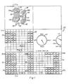
- FIG 1 illustrates a typical presentation on the video display 20 of the Lisp computing system 10 shown in Figure 4.
- the system used in this preferred embodiment is a LAMBDA compuing system from Lisp Machine, Inc., designed for execution of LISP program instructions.
- the LAMBDA system and the use of the LISP programs are set out in detail in the following manuals of Lisp Machine, Inc.:
- Field 3 1 a contains a three-dimensional (3-D) representation of a 3-D volume. As shown in Fig. 1, this 3-D representation has been excavated to display the volumes shown as 30a, 30b, 35 and 36. Before the excavation, the display would have typically been of 3-D representation of a rectangular solid.
- the rectangular solid is a tessellation of cells such as 35, 36, which in this preferred embodiment, are also rectangular solids. In the accompanying Lisp program, the cells are referred to as "voxels".
- Field 3 1 b is a top view of the 3-D representation of field 31a illustrating top surfaces 32 and 38, as well as the, individual cells 35 and 36.
- Field 31 c is a front view of the 3-D representation of field 31 a illustrating solids 30a, and 30b, and cells 35 and 36.
- Field 31d is a right side view of the 3-D representation of field 31 a with volume 30b visible, along with cells 35 and 36.
- field 31e illustrates a positioning mechanism for specifying viewing the front, left, back and right sides by indication on dial 43.
- the top, bottom and side may be viewed by indication on dial 44.
- the computer system includes a cursor which is movable in the face of the display by moving mouse 21 of Fig. 4 .
- the cursor (not shown) may point at any specific cell in any of fields 31a-31d.
- an excavation is then electronically accomplished by activating a switch on the mouse 21.
- This program is described in detail. Also, the program for causing the viewing angle to change via dial 43 and dial 44 is explained in detail.
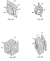
- Figure 2a illustrates a three-dimensional representation after an excavation has been performed showing solid object 51 with cells 52.
- Figure 2b shows a similar structure, but from a different view angle and also using spheres 62 as the cell configuration in place of the rectangular solid cells 52 of Fig. 2a.
- the rectangular solid is the preferred cell in this embodiment, spheres or other geometric volumes could be used.
- Figure 3a shows a three-dimensional representation 71 made up of rectangular solid cells 72.
- Figure 3b shows that the same three-dimensional representation 71 with cells 72 from a different viewing angle.
- FIG. 4 illustrates the LISP machine of this invention.
- a LISP processor 11 is connected via bus 17 (a Texas Instruments NUBUS type bus to a Motorola 68,000 processor 12, main memory 1 3, display controller 14 and system diagnostic unit 15.
- the main memory 13 stores the three-dimensional data array and the designator bit array.
- a display controller 14 controls video display 20 which is connected to RS232 interface 18. Keyboard 22 and mouse 21 are interfaced to the video display 20.
- the details of system 10 may be referred to in the aforementioned LISP Machine, Inc. publications.
- Each cell of the Data Array is displayed as a small cube or sphere (voxel) when the corresponding Designator Array bit is one (1).
- the displayed color or shade of the voxel is specified by the corresponding number in the Data Array.
- the display appears as a large rectangular solid with a colored surface that varies in proportion to the corresponding Data Array values.
- all designator bits are zero, nothing appears in the display.
- the primary use of this method is to examine volumes by selecting some designator bits to be one (1) and others to be zero, resulting in a display representing a carving of the Data Array into arbitrary 3D shapes, voxel by voxel.
- the program draws all voxels designated for display, although some voxels may not be visible when the display method is finished. That is because voxels are drawn in an order scanning the Data Array "from farthest to nearest" with respect to the viewer, to eliminate hidden voxels from view.
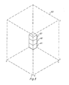
- Fig. 5 illustrates cells 81, 82, and 83 being created in the farthest comer of prospective 3-D representation 80. First, cell 81 is created, then 82, 83, and so on, until the column is completed. Then, the next designated adjacent column is created.
- One of the problems solved by the COMPUTE-ORIGIN-AND-VIEWING-CONSTANTS method in the program is to determine an appropriate size for each voxel so that the display of the entire volume will fit in the window.
- the summary of the method below is simplified by assuming that the window is big enough to accommodate an arbitrarily chosen voxel size.
- STEP 1 Let XMAX, YMAX, and ZMAX be the maximum subscripts of the Data Array in the three dimensions. The minimum subscript of each dimension is zero.
- VIEW-VECTOR (A B C) be a vector pointing in the direction of gaze (this represents the viewing angle).
- STEP 2 Compute the SCAN-ORDER. That is, determine an order for scanning the Data Array "from farthest to nearest" with respect to the viewer.
- the scan order is represented as a list of three numbers, (DX DY DZ).
- DY and DZ represent the scan order with respect to the Y and Z axes.
- the VERTICES indicated as P0, PX, PY, and PZ represent the same points as AO, AX, AY, and AZ, except there the origin of the array is regarded as being at the center of the array instead of at (0 0 0).
- the program uses the other origin as part of a scheme for centering the center of the Data Array in the window regardless of the particular designator and viewing angle.
- STEP 4 Compute the image of AO, AX, AY, and AZ.
- WO (wxo,wyo)
- WX (wxx,wyx)
- WY (wxy,wyy)
- WZ (wxz, wyz)
- the VIEW-TRANSFORMATION function performs the projection.
- the WINDOW-TRANSFORMATION function is part of the scaling to translate the image coordinates into window coordinates. Without loss of generality, the rest of this discussion assumes that WO, WX, WY, and WZ are in window coordinates.
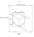
- STEP 5 Compute five constants, Xdx, Ydx, Xdy, Ydy, and Zdy, corresponding to the distances in the Figure 6.
- the drawing illustrates one voxel depicted as a small cube.
- the importance of the five constants is that they describe the directional displacements in the image between adjacent voxels.
- Zdy describes the vertical displacement (dy) of two voxels in the image due to a unit displacement in the scanning direction along the Z axis of the Data Array, i.e. the displacement between two voxels corresponding to Data Array positions, (X,Y,Z) and (X,Y,Z+DZ).
- (Xdx Xdy) describes the combined horizontal (dx) and vertical (dy) displacement of two voxels due to a unit displacement along the X axis of the Data Array.
- (Ydx Ydy) describes the combined horizontal (dx) and vertical (dy) displacement of two voxels due to a unit displacement along the Y axis of the Data Array.
- the five constants can be computed using the SCAN-ORDER, WO, WX, WY, WZ, XMAX, YMAX, and ZMAX as follows, where the asterisk denotes multiplication: STEP 6: Compute a picture of the voxel. The particular picture- used to represent each voxel is arbitrary.
- the MASK (which may be thought of as a silhouette view of the voxel).
- the MASK designates the area of the rectanglular array that PICTURE occupies, e.g. for a Lisp Machine ART-1 B pixel array the MASK has one (1) bits everywhere the voxel is depicted as opaque. In the innermost loop of Step 8, the MASK is used to erase the appropriate area of the window in preparation for inserting the PICTURE, using a series of calls to the Lisp Machine BITBLT function.
- the ORIGIN is computed from WO, WX, WY, and WZ using the signs (plus or minus) of DX, DY, and DZ, by the relationship in the following table, where the operations are vector addition and subtraction.
- STEP 8 Scan the Designator Array and Data Array in the scanning order, drawing the voxel picture for each designated datum in sequence.
- This step is extremely efficient since the positions of voxels in the window can be determined with just a small number of additions and comparisons per voxel, and because the series of BITBLT operations used to copy each voxel picture into the screen exploits the speed of BITBLT.
- This step consists of three nested loops. The outermost loop steps X along the X axis of the Data Array and keeps track of the displacement of each voxel from the ORIGIN due to the displacement of X along the X axis. The middle loop steps Y along the Y axis
- VIS00 1 .LSP is entitled "Array-Display, Lisp".
- This program is employed in the system to implement the display of the top, front, and sides view in fields 31b, 31 and 31d, respectively, of Fig. 1.
- This short program defines a virtual window of an array that is updated when the array itself is altered as by an excavation procedure.
- the virtual window technique is set out in program VIS009.LSP entitled "Virtual-Windows. Lisp".
- the virtual window system is described in the introductory material to the program VIS009.LSP.
- Program VIS003.LSP entitled “Color-Graphics.Lisp” is a low level primitive program which is used for drawing each cell and is employed in program VIS010.
- Program VIS004.LSP entitled "Dashboard-Dials.Lisp” is a program for drawing the dials as shown in field 31 e of Fig. 1.
- Program VIS005.LSP entitled “Mouse-Handler-Mixin.Lisp” and program VIS006.LSP entitled “Mouse-Handler-Utlites. Lisp” describe a method for moving and operating mouse 21 of Fig. 4. As indicated earlier, a cursor is employed to point to cells in any of fields 31 a-31 d of Fig. 1 and also to desired directions in field 31 e. In general terms, a cell may be created or deleted by "clicking" the mouse on cells of the solid object in field 31a The first click highlights a cell at one comer of a rectangular volume to be created or deleted, and the second click specifies the opposite comer and performs the operation.
- the left mouse button is for creating and the middle button is for deleting.
- a single click specifies the visible cell at the mouse cursor and a double click specifies an empty cell location closest to the viewpont at the mouse cursor.
- a triple click cancels a partially completed operation.
- cells can be created or deleted by specifying opposite comers of a rectangle in one of the three mutually orthogonal silhouette view windows illusrated in fields 31 b-31 d.
- cells are created or deleted at all cell locations in-line with the specified rectangle from that point of view. For example, when a rectangle is specified in the top view field 31 b, all cells in the columns directly under the rectangle are affected.
- the first click of the mouse marks the position of one comer and the second click marks the opposite comer of the rectangle (which may degenerate to a single element or row). Both clicks must be of the same type (left create or middle: delete).
- a cell can be created or deleted at a single point by clicking the two points in different orthogonal views.
- the angle from which the 3-D display is viewed is changed by clicking the dials in the viewing position window 31e.
- the dials are designed as if the object is at the center of each dial and the viewpoint is on the perimeter.
- Dial 43 controls the horizontal component of the viewing position, while dial 4 4 specifies the vertical component
- click the mouse at dial 43 between RIGHT and FRONT click at dial 44 between the SIDE (horizontal position) and the TOP (looking straight down) position.
- the program VIS003.LSP entitled "Color-Graphics.Lisp” controls how the cells are colored, either collectively or individually. For example, a list of six colors, one for each of the six faces, causes cube cell faces to be uniformly colored -- all Rights faces are, for example, blue while all Top faces are red. Cells can also be individually colored by specifying a 3-D array of colors where the color of a cell is the color in the color array position corresponding to the cell position in the 3-D bit array.
- Program VIS007.LSP entitled “Movie.Lisp” provides for producing two types of movies: (1) the object rotating in place, and (2) a scan of the object as it appears while it is being drawn one frame per plane of the solid object.
- Movies of the object rotating in place are made by specifying a starting viewing position and a final view (the last frame of the movie).
- the N frames of the movie are then interpolated between the two views; the horizon viewing position for dial 43 advances counter-clockwise.
- the starting view is specified before performing the make movie command.
- another window provides for optionally changing some default parameters of the movie (e.g. the number of frames).
- the program solicits the final view specification as specified in field 3 1 e. Clicking the middle button of the mouse 21 produces the movie; clicking the Right button aborts the procedure.
- the scanning movies depict the solid object as it is being drawn, one frame per plane, in any of six scanning directions (i.e., top-to-bottom, right-to-left, etc.). Scanning movies allow extremely rapid browsing of planar sections of the object, incrementally building up and tearing down the solid object plane by plane (frame by frame).
- a move dial appears in the viewing position window 31 e for controlling the showing of the movie interactively using the Movie Display system on the Lisp machine.
- Program VIS011.LSP entitled “Volume Inspector Method.Lisp”, as can be seen, is the program employed for the excavation feature. The method of this program is described above.
- program VIS012.LSP entitled “Windows.Lisp” is a low level primitive program for creating the windows in Fig. 1 to contain fields 31 a-31 e, plus the blank field.
Landscapes
- Physics & Mathematics (AREA)
- Engineering & Computer Science (AREA)
- Computer Graphics (AREA)
- Geometry (AREA)
- Software Systems (AREA)
- General Physics & Mathematics (AREA)
- Theoretical Computer Science (AREA)
- Image Generation (AREA)
- Processing Or Creating Images (AREA)
- Eye Examination Apparatus (AREA)
- Apparatus For Radiation Diagnosis (AREA)
Abstract
Description
- This invention relates to a two-dimensional display of a three-dimensional volume representation and more particularly to such a representation where designated portions of the volume may be excavated, revealing the portion imme- diatety adjacent the excavated portion.
- Prior art displays have generally involved two-dimensional cross sections of three-dimensional arrays.
- In more recent prior art systems, a three-dimensional rectangular solid is displayed with the visible sides having varying color in proportion to a selected parameter in the array along those sides.
- Another prior art technique is to produce movies of successive-two-dimensional cross-sections of a three-dimensional array, effectively allowing the user to "drive through" the array.
- These prior art methods tend to rely on the imagination of human interpreters to mentally construct three-dimensional models of the data, based on the two-dimensional cross sections.
- The colored rectangular solid displays come closest to conveying the desired three-dimensional arrangements, but still rely on imagination to appreciate the overall three-dimensional structure of the data on the basis of the sides of the rectangular solids.
- A computer system receives a three-dimensional array, representing a three-dimensional volume. The three-dimensional array is stored in memory in the form of a plurality of digital numbers. A designator, in the form of a three-dimensional array of bits, has each bit assigned to represent one digital number in the three-dimensional array. A color is assigned to each digital number.
- A two-dimensional display. is employed to show a three-dimensional representation. This three-dimensional representation is a tessellation of cells, each cell representing one of the digital numbers. The cell is colored to correspond to the associated digital number. The color may be a shading from black to white in a black and white display and may be any selection of colors in a color display.
- In this preferred embodiment, the three-dimensional array is in the form of a rectangular solid and each cell is also in the form of a rectangular solid. The designator array of bits designates which of the cells will be displayed. In this preferred embodiment, a "0" bit designates that the cell will not be displayed while a "1" bit designates that the cell will be displayed. A cell which is designated for display will not actually be visible in the display if other designated cells occlude it. A movable cursor is provided in the two-dimensional display. In this preferred embodiment, a mouse controls the movement of the cursor. To excavate a portion of the volume, the user moves the cursor and points to a cell by moving the mouse, to excavate a single column of cells, or to two cells to define the limits to be excavated. The excavation is done by activating a switch on the mouse which then enables the system to set all of the designator array bits to "0" for those bits corresponding to cells to be excavated. The two-dimensional display of the three-dimensional representation is then redrawn to comply with the designator array as altered by the excavation to then illustrate the three-dimensional representation revealing those cells immediately adjacent the excavated cells, but not formerly visible.
- The three-dimensional viewing angle may be changed by the system to show the three-dimensional volume representation from any desired angle. The three-dimensional volume representation may therefore be effectively rotated in any direction to permit the user to see any side.
- The principal object of this invention is to provide a three-dimensional representation on a two-dimensional display of a three-dimensional array wherein desired portions may be excavated to reveal the underlying portions.
- Another object of this invention is to provide a three-dimensional representation on a two-dimensional display formed by a tessellation of cells, selected cells being removable when an excavation is made.
- Still another object of this invention is to provide a display wherein the cells are colored in accordance with corresponding digital numbers in a three-dimensional array.
- These and other objects will be made evident in the detailed description that follows.
-
- Figure 1 illustrates a typical cathode array tube (CRT) display of this invention.
- Figure 2a illustrates a three-dimensional representation made up of rectangular solid cells.
- Figure 2b illustrates the representation of Figure 2a, but using spherical cells.
- Figures 3a and 3b illustrate a three-dimensional representation from different viewing angles.
- Figure 4 is a block diagram of the computer system of this invention.
- Figure 5 illustrates the creating of the three-dimensional representation.
- Figure 6 shows the measurement requirements for creating the three-dimensional cell.
- Figure 1 illustrates a typical presentation on the
video display 20 of the Lispcomputing system 10 shown in Figure 4. The system used in this preferred embodiment is a LAMBDA compuing system from Lisp Machine, Inc., designed for execution of LISP program instructions. The LAMBDA system and the use of the LISP programs are set out in detail in the following manuals of Lisp Machine, Inc.: - "Instroduction to the Lisp System" - 1983;
- "ZMACS-Instroductory Manual" - 1983;
- "ZMAIL Manual" - April 1983;
- "Window System Manual" - August 1983;
- "Lisp Machine Manual" - January 1983;
- "System 94 Release Notes" - Undated
- Field 31a contains a three-dimensional (3-D) representation of a 3-D volume. As shown in Fig. 1, this 3-D representation has been excavated to display the volumes shown as 30a, 30b, 35 and 36. Before the excavation, the display would have typically been of 3-D representation of a rectangular solid. The rectangular solid is a tessellation of cells such as 35, 36, which in this preferred embodiment, are also rectangular solids. In the accompanying Lisp program, the cells are referred to as "voxels".
- Field 31 b is a top view of the 3-D representation of field 31a illustrating
top surfaces individual cells - Field 31 c is a front view of the 3-D representation of field 31 a
illustrating solids 30a, and 30b, andcells - Field 31d is a right side view of the 3-D representation of field 31 a with
volume 30b visible, along withcells - Finally, field 31e illustrates a positioning mechanism for specifying viewing the front, left, back and right sides by indication on
dial 43. The top, bottom and side may be viewed by indication ondial 44. - The computer system includes a cursor which is movable in the face of the display by moving
mouse 21 of Fig. 4. The cursor (not shown) may point at any specific cell in any of fields 31a-31d. By pointing at the cells which define a desired volume to be removed, an excavation is then electronically accomplished by activating a switch on themouse 21. This program is described in detail. Also, the program for causing the viewing angle to change viadial 43 and dial 44 is explained in detail. - Figure 2a illustrates a three-dimensional representation after an excavation has been performed showing
solid object 51 withcells 52. - Figure 2b shows a similar structure, but from a different view angle and also using
spheres 62 as the cell configuration in place of the rectangularsolid cells 52 of Fig. 2a. The rectangular solid is the preferred cell in this embodiment, spheres or other geometric volumes could be used. - Figure 3a shows a three-dimensional representation 71 made up of rectangular
solid cells 72. - Figure 3b shows that the same three-dimensional representation 71 with
cells 72 from a different viewing angle. - The displays of Figures 2a-2b and Figures 3a-3b are not shown in color or in shading. It should be noted, however, that the cells are customarily colored in accordance with designating digital numbers. It should also be noted that in this preferred embodiment, seismic data provides the three-dimensional source data. Any other appropriate data would serve as well. For example, Nuclear Magnetic Resonance (NMR) imagery is contemplated.
- Figure 4 illustrates the LISP machine of this invention. In block form, a LISP processor 11 is connected via bus 17 (a Texas Instruments NUBUS type bus to a Motorola 68,000
processor 12, main memory 13,display controller 14 and systemdiagnostic unit 15. Themain memory 13 stores the three-dimensional data array and the designator bit array. Adisplay controller 14controls video display 20 which is connected toRS232 interface 18.Keyboard 22 andmouse 21 are interfaced to thevideo display 20. The details ofsystem 10 may be referred to in the aforementioned LISP Machine, Inc. publications. - Please refer to Figs. 5 and 6, in particular, together with the other figures, for an understanding of the operation of this invention.
- Referring to the Lisp program listing which is set out in the Appendix and incorporated herein by reference, programs VIS001.LSP-VIS012.LSP are seen to provide the entire program for the system. With respect to program VIS008.LSP and VIS010.LSP, entitled "Volume-Display-Method.Lisp", the following description of the method contained in these two programs is set out in detail.
- Data Array:
- A 3D array (volume) of numbers (e.g. 3D seismic or NMR data). Note: In the program the Data Array is referred to as the VOXEL-COLOR, a 3D array of integers in [0:15]. To display a different range of values using this program, the data must first be converted to an array containing numbers in [0:15]. The [0.15] numbers correspond to the sixteen colors of the particular display software used by the program.
- Designator Array:
- A 3D array of bits, one bit for each datum in the Data Array. A one-bit designates the corresponding datum to be included in the display, and a zero-bit designates that it will not be included. A datum which is designated for display will not actually be visible in the display if other designated data occlude it. Note: In the program the Designator Array is referred to as the POINT-ARRAY.
- Viewing Angles:
- Two angles, theta and phi, respectively specify the vertical and horizontal components of the 3D viewing angle, as in a spherical coordinate system. The X and Y axes of the Data Array are arbitrarily regarded as lying in a horizontal plane, and the positive direction along the (vertical) Z dimension is regarded as pointing upward. Note: Theta and phi can be converted to a VIEW-VECTOR, the actual input expected by the program, using the VIEW-ANGLE function (in file: VIEW-ANGLE).
- Window:
- Note: In the program, a Lisp Machine window must also be given. It specifies where the display will be drawn.
- Each cell of the Data Array is displayed as a small cube or sphere (voxel) when the corresponding Designator Array bit is one (1). The displayed color or shade of the voxel is specified by the corresponding number in the Data Array. Thus when all designator bits are one (1), the display appears as a large rectangular solid with a colored surface that varies in proportion to the corresponding Data Array values. When all designator bits are zero, nothing appears in the display. The primary use of this method is to examine volumes by selecting some designator bits to be one (1) and others to be zero, resulting in a display representing a carving of the Data Array into arbitrary 3D shapes, voxel by voxel.
- The program draws all voxels designated for display, although some voxels may not be visible when the display method is finished. That is because voxels are drawn in an order scanning the Data Array "from farthest to nearest" with respect to the viewer, to eliminate hidden voxels from view.
- Fig. 5 illustrates
cells D representation 80. First,cell 81 is created, then 82, 83, and so on, until the column is completed. Then, the next designated adjacent column is created. - One of the problems solved by the COMPUTE-ORIGIN-AND-VIEWING-CONSTANTS method in the program is to determine an appropriate size for each voxel so that the display of the entire volume will fit in the window. The summary of the method below is simplified by assuming that the window is big enough to accommodate an arbitrarily chosen voxel size.
- The technique used by the program to display dach individual voxel picture (using a series of Lisp Machine BITBLT operations) is not explained in detail because it is a state-of-the-art techique, employed for example in part by the Lisp Machine system when it moves a blinker (cursor) to follow the mouse input device.
- STEP 1: Let XMAX, YMAX, and ZMAX be the maximum subscripts of the Data Array in the three dimensions. The minimum subscript of each dimension is zero. Let VIEW-VECTOR = (A B C) be a vector pointing in the direction of gaze (this represents the viewing angle).
- STEP 2: Compute the SCAN-ORDER. That is, determine an order for scanning the Data Array "from farthest to nearest" with respect to the viewer. The scan order is represented as a list of three numbers, (DX DY DZ). DX = 1 indicates that the scan order, with respect the the X axis, proceeds in the positive direction (from 0 to XMAX), and DX = -1 indicates that the X axis is scanned in the negative direction (from XMAX to 0). Similarly, DY and DZ represent the scan order with respect to the Y and Z axes.

XMAX 0 0), (0 YMAX 0), and (0 0 ZMAX), respectively. Note: In the program the VERTICES indicated as P0, PX, PY, and PZ represent the same points as AO, AX, AY, and AZ, except there the origin of the array is regarded as being at the center of the array instead of at (0 0 0). The program uses the other origin as part of a scheme for centering the center of the Data Array in the window regardless of the particular designator and viewing angle. - STEP 4: Compute the image of AO, AX, AY, and AZ. Using a version of orthographic projection in which the vertical axis of the image lies in a plane with the Z axis of the Data Array, the four points are mapped into WO = (wxo,wyo), WX=(wxx,wyx), WY=(wxy,wyy), and WZ = (wxz, wyz), according to the VIEW-VECTOR. Note: In the program, the VIEW-TRANSFORMATION function performs the projection. The WINDOW-TRANSFORMATION function is part of the scaling to translate the image coordinates into window coordinates. Without loss of generality, the rest of this discussion assumes that WO, WX, WY, and WZ are in window coordinates.
- STEP 5: Compute five constants, Xdx, Ydx, Xdy, Ydy, and Zdy, corresponding to the distances in the Figure 6. The drawing illustrates one voxel depicted as a small cube. The importance of the five constants is that they describe the directional displacements in the image between adjacent voxels. Zdy describes the vertical displacement (dy) of two voxels in the image due to a unit displacement in the scanning direction along the Z axis of the Data Array, i.e. the displacement between two voxels corresponding to Data Array positions, (X,Y,Z) and (X,Y,Z+DZ). (Xdx Xdy) describes the combined horizontal (dx) and vertical (dy) displacement of two voxels due to a unit displacement along the X axis of the Data Array. Similarly, (Ydx Ydy) describes the combined horizontal (dx) and vertical (dy) displacement of two voxels due to a unit displacement along the Y axis of the Data Array. The five constants can be computed using the SCAN-ORDER, WO, WX, WY, WZ, XMAX, YMAX, and ZMAX as follows, where the asterisk denotes multiplication:


- Note: In the program, cube pictures are computed by the CREATE-CUBE-PICTURE method of the UNIT-CUBE flavor, and sphere pictures are created by the CREATE-SPHERE-PICTURE function. Both of these procedures are straightforward exercises for students of computer graphics. Each routine actually returns two pixel arrays to represent the voxel. One is called the PICTURE (which may be thought of as a line drawing of the voxel) and the other is
- called the MASK (which may be thought of as a silhouette view of the voxel). The MASK designates the area of the rectanglular array that PICTURE occupies, e.g. for a Lisp Machine ART-1 B pixel array the MASK has one (1) bits everywhere the voxel is depicted as opaque. In the innermost loop of Step 8, the MASK is used to erase the appropriate area of the window in preparation for inserting the PICTURE, using a series of calls to the Lisp Machine BITBLT function.
- STEP 7: Determine the OR)G)N=(Ox Oy) in the image where the first voxel will be drawn. The ORIGIN is computed from WO, WX, WY, and WZ using the signs (plus or minus) of DX, DY, and DZ, by the relationship in the following table, where the operations are vector addition and subtraction.

- and keeps track of the displacement from the ORIGIN due to the displacement of Y. The innermost loop steps Z along the Z axis, keeps track of the displacement due to Z, and draws the voxel at the window position corresponding to Data Array position (X Y Z) when the (X Y Z) designator bit is one (1). An abstract of the important portions of the Lisp program implementing the three nested loops is given below. This abstract only illustrates the special case oc- curing when the SCAN-ORDER = (DX DY DZ) = (1 1 1), and uses the notation consistent with this summary of the Volume Display Method (which differs somewhat from the notation in the full version of the program). The full version of the program implements the general case where the SCAN-ORDER values may have other signs.
-

- VIS001.LSP is entitled "Array-Display, Lisp". This program is employed in the system to implement the display of the top, front, and sides view in
fields 31b, 31 and 31d, respectively, of Fig. 1. This short program defines a virtual window of an array that is updated when the array itself is altered as by an excavation procedure. - The virtual window technique is set out in program VIS009.LSP entitled "Virtual-Windows. Lisp". The virtual window system is described in the introductory material to the program VIS009.LSP.
- Program VIS003.LSP entitled "Color-Graphics.Lisp" is a low level primitive program which is used for drawing each cell and is employed in program VIS010.LSP - entitled "Volume-Display Method.Lisp", previously described.
- Program VIS004.LSP entitled "Dashboard-Dials.Lisp" is a program for drawing the dials as shown in field 31 e of Fig. 1.
- Program VIS005.LSP entitled "Mouse-Handler-Mixin.Lisp" and program VIS006.LSP entitled "Mouse-Handler-Utlites. Lisp" describe a method for moving and operating
mouse 21 of Fig. 4. As indicated earlier, a cursor is employed to point to cells in any of fields 31 a-31 d of Fig. 1 and also to desired directions in field 31 e. In general terms, a cell may be created or deleted by "clicking" the mouse on cells of the solid object in field 31a The first click highlights a cell at one comer of a rectangular volume to be created or deleted, and the second click specifies the opposite comer and performs the operation. In this particular embodiment, the left mouse button is for creating and the middle button is for deleting. A single click specifies the visible cell at the mouse cursor and a double click specifies an empty cell location closest to the viewpont at the mouse cursor. A triple click cancels a partially completed operation. These particular combinations are, of course, completely arbitrary and could obviously be rearranged to perform the same functions. - Also, cells can be created or deleted by specifying opposite comers of a rectangle in one of the three mutually orthogonal silhouette view windows illusrated in
fields 31 b-31 d. In this case, cells are created or deleted at all cell locations in-line with the specified rectangle from that point of view. For example, when a rectangle is specified in thetop view field 31 b, all cells in the columns directly under the rectangle are affected. The first click of the mouse marks the position of one comer and the second click marks the opposite comer of the rectangle (which may degenerate to a single element or row). Both clicks must be of the same type (left create or middle: delete). A double click cancels a partially completed operation. A cell can be created or deleted at a single point by clicking the two points in different orthogonal views. - With respect to field 31e, the angle from which the 3-D display is viewed is changed by clicking the dials in the viewing position window 31e. The dials are designed as if the object is at the center of each dial and the viewpoint is on the perimeter.
Dial 43 controls the horizontal component of the viewing position, while dial 44 specifies the vertical component Thus, to look at the right, front, and top sides of an object, click the mouse atdial 43 between RIGHT and FRONT, and click atdial 44 between the SIDE (horizontal position) and the TOP (looking straight down) position. - The program VIS003.LSP entitled "Color-Graphics.Lisp" controls how the cells are colored, either collectively or individually. For example, a list of six colors, one for each of the six faces, causes cube cell faces to be uniformly colored -- all Rights faces are, for example, blue while all Top faces are red. Cells can also be individually colored by specifying a 3-D array of colors where the color of a cell is the color in the color array position corresponding to the cell position in the 3-D bit array.
- Program VIS007.LSP entitled "Movie.Lisp" provides for producing two types of movies: (1) the object rotating in place, and (2) a scan of the object as it appears while it is being drawn one frame per plane of the solid object.
- Movies of the object rotating in place are made by specifying a starting viewing position and a final view (the last frame of the movie). The N frames of the movie are then interpolated between the two views; the horizon viewing position for
dial 43 advances counter-clockwise. The starting view is specified before performing the make movie command. After clicking the make movie option, another window provides for optionally changing some default parameters of the movie (e.g. the number of frames). After leaving that window, the program solicits the final view specification as specified in field 31e. Clicking the middle button of themouse 21 produces the movie; clicking the Right button aborts the procedure. - The scanning movies depict the solid object as it is being drawn, one frame per plane, in any of six scanning directions (i.e., top-to-bottom, right-to-left, etc.). Scanning movies allow extremely rapid browsing of planar sections of the object, incrementally building up and tearing down the solid object plane by plane (frame by frame).
- When the Show Movie option is selected, a move dial appears in the viewing position window 31 e for controlling the showing of the movie interactively using the Movie Display system on the Lisp machine.
- Program VIS011.LSP entitled "Volume Inspector Method.Lisp", as can be seen, is the program employed for the excavation feature. The method of this program is described above.
- Finally, program VIS012.LSP entitled "Windows.Lisp" is a low level primitive program for creating the windows in Fig. 1 to contain fields 31 a-31 e, plus the blank field.
- The particular programming language and the hardware set out above are exemplary and are not intended to limit this invention. It is contemplated that transformation of programming language and substitution of computer components is certainty within the realm of those skilled in the art. The invention is limited only by the appended claims.


Claims (20)
Applications Claiming Priority (2)
| Application Number | Priority Date | Filing Date | Title |
|---|---|---|---|
| US06/637,465 US4685070A (en) | 1984-08-03 | 1984-08-03 | System and method for displaying, and interactively excavating and examining a three dimensional volume |
| US637465 | 1991-01-04 |
Publications (2)
| Publication Number | Publication Date |
|---|---|
| EP0180296A2 true EP0180296A2 (en) | 1986-05-07 |
| EP0180296A3 EP0180296A3 (en) | 1989-11-23 |
Family
ID=24556064
Family Applications (1)
| Application Number | Title | Priority Date | Filing Date |
|---|---|---|---|
| EP85305540A Withdrawn EP0180296A3 (en) | 1984-08-03 | 1985-08-02 | System and method for displaying and interactively excavating and examining a three dimensional volume |
Country Status (4)
| Country | Link |
|---|---|
| US (1) | US4685070A (en) |
| EP (1) | EP0180296A3 (en) |
| CA (1) | CA1246239A (en) |
| NO (1) | NO853061L (en) |
Cited By (2)
| Publication number | Priority date | Publication date | Assignee | Title |
|---|---|---|---|---|
| GB2354684A (en) * | 1999-05-24 | 2001-03-28 | Parametric Tech Corp | Identifying peripheral elements of a geometrical representation of an object |
| GB2354685A (en) * | 1999-05-24 | 2001-03-28 | Parametric Tech Corp | Creating a tessellated approximation of a geometrical representation of an object |
Families Citing this family (70)
| Publication number | Priority date | Publication date | Assignee | Title |
|---|---|---|---|---|
| JP2526857B2 (en) * | 1984-12-27 | 1996-08-21 | ソニー株式会社 | Image signal conversion method |
| CA1250064A (en) * | 1985-03-29 | 1989-02-14 | Kenichi Anjyo | Method for constructing three-dimensional polyhedron model |
| JPH0681275B2 (en) * | 1985-04-03 | 1994-10-12 | ソニー株式会社 | Image converter |
| US4817005A (en) * | 1985-07-05 | 1989-03-28 | Dai Nippon Insatsu Kabushiki Kaisha | Method of designing cubic receptacle and apparatus therefor |
| US4907188A (en) * | 1985-09-12 | 1990-03-06 | Kabushiki Kaisha Toshiba | Image information search network system |
| JPH0756678B2 (en) * | 1985-11-01 | 1995-06-14 | 株式会社日立製作所 | Interactive shape modeling system |
| US4845656A (en) * | 1985-12-12 | 1989-07-04 | Kabushiki Kaisha Toshiba | System for transferring data between memories in a data-processing apparatus having a bitblt unit |
| US4835712A (en) * | 1986-04-14 | 1989-05-30 | Pixar | Methods and apparatus for imaging volume data with shading |
| US4821214A (en) * | 1986-04-17 | 1989-04-11 | Brigham Young University | Computer graphics method for changing the shape of a geometric model using free-form deformation |
| JPH0785271B2 (en) * | 1986-06-27 | 1995-09-13 | 株式会社日立製作所 | Shape modeling method |
| US4888713B1 (en) * | 1986-09-05 | 1993-10-12 | Cdi Technologies, Inc. | Surface detail mapping system |
| DE3782160T2 (en) * | 1986-09-11 | 1993-02-11 | Hughes Aircraft Co | DIGITAL SIMULATION SYSTEM FOR GENERATING REALISTIC SCENES. |
| US4884069A (en) * | 1987-03-19 | 1989-11-28 | Apple Computer, Inc. | Video apparatus employing VRAMs |
| US4821210A (en) * | 1987-04-02 | 1989-04-11 | General Electric Co. | Fast display of three-dimensional images |
| US4982438A (en) * | 1987-06-02 | 1991-01-01 | Hitachi, Ltd. | Apparatus and method for recognizing three-dimensional shape of object |
| US4928233A (en) * | 1987-08-24 | 1990-05-22 | International Business Machines | System for providing three dimensional object descriptions |
| US5129013A (en) * | 1987-10-13 | 1992-07-07 | At&T Bell Laboratories | Graphics image editor |
| US4876673A (en) * | 1988-01-19 | 1989-10-24 | Mobil Oil Corporation | Display of common depth point seismic data with velocity correction in real time |
| US5255207C1 (en) * | 1988-06-16 | 2001-01-09 | Larry Cornwell | Method for designing and detailing cabinets |
| US5019809A (en) * | 1988-07-29 | 1991-05-28 | University Of Toronto Innovations Foundation | Two-dimensional emulation of three-dimensional trackball |
| US5617332A (en) * | 1988-08-10 | 1997-04-01 | Fressola; Alfred A. | Method and system for producing stereographic images of celestial objects |
| US4987554A (en) * | 1988-08-24 | 1991-01-22 | The Research Foundation Of State University Of New York | Method of converting continuous three-dimensional geometrical representations of polygonal objects into discrete three-dimensional voxel-based representations thereof within a three-dimensional voxel-based system |
| US6240308B1 (en) * | 1988-12-23 | 2001-05-29 | Tyrone L. Hardy | Method and apparatus for archiving and displaying anatomico-physiological data in a normalized whole brain mapping and imaging system |
| EP0382495B1 (en) * | 1989-02-08 | 2000-04-26 | Canon Kabushiki Kaisha | Figure processing apparatus |
| US5081698A (en) | 1989-02-14 | 1992-01-14 | Intel Corporation | Method and apparatus for graphics display data manipulation |
| US5067098A (en) * | 1989-03-31 | 1991-11-19 | The Ohio State University Research Foundation | Slope-aspect color shading for parametric surfaces |
| US5113357A (en) * | 1989-05-18 | 1992-05-12 | Sun Microsystems, Inc. | Method and apparatus for rendering of geometric volumes |
| JP3245655B2 (en) * | 1990-03-05 | 2002-01-15 | インキサイト ソフトウェア インコーポレイテッド | Workspace display processing method |
| JP2892430B2 (en) * | 1990-03-28 | 1999-05-17 | 株式会社日立製作所 | Method and apparatus for displaying physical quantity |
| FR2662009B1 (en) * | 1990-05-09 | 1996-03-08 | Apple Computer | MULTIPLE FACES MANOPULABLE ICON FOR DISPLAY ON COMPUTER. |
| US5319395A (en) * | 1990-05-16 | 1994-06-07 | International Business Machines Corporation | Pixel depth converter for a computer video display |
| US5133073A (en) * | 1990-05-29 | 1992-07-21 | Wavetracer, Inc. | Processor array of N-dimensions which is physically reconfigurable into N-1 |
| US5157785A (en) * | 1990-05-29 | 1992-10-20 | Wavetracer, Inc. | Process cell for an n-dimensional processor array having a single input element with 2n data inputs, memory, and full function arithmetic logic unit |
| US5201035A (en) * | 1990-07-09 | 1993-04-06 | The United States Of America As Represented By The Secretary Of The Air Force | Dynamic algorithm selection for volume rendering, isocontour and body extraction within a multiple-instruction, multiple-data multiprocessor |
| WO1992007350A1 (en) * | 1990-10-15 | 1992-04-30 | National Biomedical Research Foundation | Three-dimensional cursor control device |
| CA2060975C (en) * | 1991-02-25 | 1998-11-10 | Gopalan Ramanujam | Scientific visualization system |
| JP2671619B2 (en) * | 1991-03-06 | 1997-10-29 | 富士通株式会社 | Video generation processor |
| JP2824342B2 (en) * | 1991-03-29 | 1998-11-11 | 富士通株式会社 | High-speed image drawing device |
| US5555352A (en) * | 1991-04-23 | 1996-09-10 | International Business Machines Corporation | Object-based irregular-grid volume rendering |
| CA2069976A1 (en) * | 1991-05-31 | 1992-12-01 | Shin-Ichi Nakazawa | Retrieval system for graphic information |
| US5298919A (en) * | 1991-08-02 | 1994-03-29 | Multipoint Technology Corporation | Multi-dimensional input device |
| US5359704A (en) * | 1991-10-30 | 1994-10-25 | International Business Machines Corporation | Method for selecting silhouette and visible edges in wire frame images in a computer graphics display system |
| US5734384A (en) * | 1991-11-29 | 1998-03-31 | Picker International, Inc. | Cross-referenced sectioning and reprojection of diagnostic image volumes |
| US5351995A (en) * | 1992-01-29 | 1994-10-04 | Apple Computer, Inc. | Double-sided, reversible electronic paper |
| US6384847B1 (en) | 1992-03-20 | 2002-05-07 | International Business Machines Corporation | Interactive graphical method for analyzing many-dimensional data sets |
| US5557714A (en) * | 1993-01-29 | 1996-09-17 | Microsoft Corporation | Method and system for rotating a three-dimensional model about two orthogonal axes |
| JPH06231275A (en) * | 1993-01-29 | 1994-08-19 | Hitachi Ltd | Image simulation method |
| DE69534331T2 (en) * | 1994-07-28 | 2006-01-12 | Xerox Corp. | Method and device for highlighting the detail of a tree structure |
| US5546529A (en) * | 1994-07-28 | 1996-08-13 | Xerox Corporation | Method and apparatus for visualization of database search results |
| JPH0895551A (en) * | 1994-09-28 | 1996-04-12 | Nikon Corp | Image display device |
| US5943037A (en) * | 1995-10-10 | 1999-08-24 | Snap-On Technologies, Inc. | Viewer orientation indicator for an illustration |
| US5847971A (en) * | 1996-01-05 | 1998-12-08 | Steelcase Incorporated | 3-D spatial GUI querying and manipulating an RDMS for order-entry applications |
| JP4046370B2 (en) * | 1996-01-12 | 2008-02-13 | 富士通株式会社 | 3D shape drawing method |
| US6144384A (en) * | 1996-02-20 | 2000-11-07 | Yugen Kashia Aloalo International | Voxel data processing using attributes thereof |
| KR100232278B1 (en) * | 1996-07-05 | 1999-12-01 | 노부히로 세키 | Apparatus of drawing a cubic view |
| US6144383A (en) * | 1997-05-30 | 2000-11-07 | Hewlett-Packard Company | Volumetric data organization method that allows for cache efficient rendering speedups and efficient graphics hardware design |
| US6111583A (en) | 1997-09-29 | 2000-08-29 | Skyline Software Systems Ltd. | Apparatus and method for three-dimensional terrain rendering |
| US6081253A (en) * | 1998-02-10 | 2000-06-27 | Bronson Color Company, Inc. | Method for generating numerous harmonious color palettes from two colors |
| US20030158786A1 (en) * | 1999-02-26 | 2003-08-21 | Skyline Software Systems, Inc. | Sending three-dimensional images over a network |
| US7502027B1 (en) * | 1999-09-13 | 2009-03-10 | Solidworks Corporation | Electronic drawing viewer |
| GB2358980B (en) * | 2000-02-07 | 2004-09-01 | British Broadcasting Corp | Processing of images for 3D display |
| WO2001063561A1 (en) * | 2000-02-25 | 2001-08-30 | The Research Foundation Of State University Of New York | Apparatus and method for volume processing and rendering |
| EP1364345A1 (en) * | 2001-03-01 | 2003-11-26 | Volume Interactions Pte. Ltd. | A display apparatus |
| US6735888B2 (en) * | 2001-05-18 | 2004-05-18 | Witten Technologies Inc. | Virtual camera on the bucket of an excavator displaying 3D images of buried pipes |
| GB2387754B (en) * | 2002-04-17 | 2004-05-19 | John Morrison | Electronic file display |
| JP3690672B2 (en) | 2002-05-17 | 2005-08-31 | 任天堂株式会社 | Game system and game program |
| US7567714B2 (en) * | 2004-07-07 | 2009-07-28 | The United States Of America As Represented By The Secretary Of The Navy | System, method and apparatus for clustering features |
| KR100916638B1 (en) * | 2007-08-02 | 2009-09-08 | 인하대학교 산학협력단 | Earthwork amount calculation device and method using structured light |
| US8456471B2 (en) * | 2008-08-26 | 2013-06-04 | Leica Geosystems | Point-cloud clip filter |
| JP7233399B2 (en) * | 2020-06-23 | 2023-03-06 | 任天堂株式会社 | GAME PROGRAM, GAME DEVICE, GAME SYSTEM, AND GAME PROCESSING METHOD |
Family Cites Families (9)
| Publication number | Priority date | Publication date | Assignee | Title |
|---|---|---|---|---|
| US3668619A (en) * | 1969-07-02 | 1972-06-06 | Mobil Oil Corp | Three-dimensional presentation of borehole logging data |
| US3638178A (en) * | 1969-12-01 | 1972-01-25 | Chevron Res | Method for processing three-dimensional seismic data to select and plot said data on a two-dimensional display surface |
| JPS57119390A (en) * | 1981-01-16 | 1982-07-24 | Tokyo Shibaura Electric Co | Shading method |
| US4439760A (en) * | 1981-05-19 | 1984-03-27 | Bell Telephone Laboratories, Incorporated | Method and apparatus for compiling three-dimensional digital image information |
| US4509043A (en) * | 1982-04-12 | 1985-04-02 | Tektronix, Inc. | Method and apparatus for displaying images |
| US4484187A (en) * | 1982-06-25 | 1984-11-20 | At&T Bell Laboratories | Video overlay system having interactive color addressing |
| US4580134A (en) * | 1982-11-16 | 1986-04-01 | Real Time Design, Inc. | Color video system using data compression and decompression |
| US4475104A (en) * | 1983-01-17 | 1984-10-02 | Lexidata Corporation | Three-dimensional display system |
| US4574357A (en) * | 1984-02-21 | 1986-03-04 | Pitney Bowes Inc. | Real time character thinning system |
-
1984
- 1984-08-03 US US06/637,465 patent/US4685070A/en not_active Expired - Lifetime
-
1985
- 1985-08-02 EP EP85305540A patent/EP0180296A3/en not_active Withdrawn
- 1985-08-02 NO NO853061A patent/NO853061L/en unknown
- 1985-08-02 CA CA000488015A patent/CA1246239A/en not_active Expired
Non-Patent Citations (2)
| Title |
|---|
| ENGINEERING, vol. 220, no. 10, October 1980, pages 1104-1108, London, GB; "Designing by computers" * |
| PROCEEDINGS OF 18TH INTERNATIONAL TECHNICAL CONFERENCE, NUMERICAL CONTROL SOCIETY, Dallas, Texas, 17th - 20th May 1981, pages 215-229, Glenview Ill. US; R.H. JOHNSON et al.: "Application of a computer aided engineering system to manufacturing" * |
Cited By (4)
| Publication number | Priority date | Publication date | Assignee | Title |
|---|---|---|---|---|
| GB2354684A (en) * | 1999-05-24 | 2001-03-28 | Parametric Tech Corp | Identifying peripheral elements of a geometrical representation of an object |
| GB2354685A (en) * | 1999-05-24 | 2001-03-28 | Parametric Tech Corp | Creating a tessellated approximation of a geometrical representation of an object |
| GB2354685B (en) * | 1999-05-24 | 2003-06-18 | Parametric Tech Corp | A method and system for creating a tessellated approximation of an outer envelope of a complex model |
| GB2354684B (en) * | 1999-05-24 | 2003-07-02 | Parametric Tech Corp | A method and system for identifying peripheral elements of a complex model |
Also Published As
| Publication number | Publication date |
|---|---|
| US4685070A (en) | 1987-08-04 |
| EP0180296A3 (en) | 1989-11-23 |
| CA1246239A (en) | 1988-12-06 |
| NO853061L (en) | 1986-02-04 |
Similar Documents
| Publication | Publication Date | Title |
|---|---|---|
| US4685070A (en) | System and method for displaying, and interactively excavating and examining a three dimensional volume | |
| US4994989A (en) | Displaying method and apparatus for three-dimensional computer graphics | |
| US5379371A (en) | Displaying method and apparatus for three-dimensional computer graphics | |
| US6229549B1 (en) | High-speed three-dimensional texture mapping systems and methods | |
| US6590573B1 (en) | Interactive computer system for creating three-dimensional image information and for converting two-dimensional image information for three-dimensional display systems | |
| EP0451875B1 (en) | Image displaying system | |
| AU2004262338B2 (en) | System and method for real-time co-rendering of multiple attributes | |
| US6940507B2 (en) | Method and apparatus for visualization of 3D voxel data using lit opacity volumes with shading | |
| EP0794516A2 (en) | Image processing method and apparatus | |
| EP0865000B1 (en) | Image processing method and apparatus | |
| US9401044B1 (en) | Method for conformal visualization | |
| Tolba et al. | A projective drawing system | |
| Chen et al. | Manipulation, display, and analysis of three-dimensional biological images | |
| Plate et al. | A flexible multi-volume shader framework for arbitrarily intersecting multi-resolution datasets | |
| MXPA03004228A (en) | System and method for analyzing and imaging three-dimensional volume data sets. | |
| EP1821258A2 (en) | Method and apparatus for automated dynamics of three-dimensional graphics scenes for enhanced 3D visualization | |
| KR100429092B1 (en) | Graphic image processing method and apparatus | |
| Kaufman | The CUBE workstation—a 3-D voxel-based graphics environment | |
| GB2238215A (en) | Computer display system with a three dimensional cursor shadow | |
| JP3615660B2 (en) | Image display apparatus and method | |
| Sourin | From Ancient Greeks to Pixels | |
| Huijsmans et al. | WAALSURF: Molecular graphics on a personal computer | |
| Tory et al. | Exovis: An overview and detail technique for volumes | |
| JPH0883352A (en) | Image processing apparatus and method | |
| JPH01149177A (en) | 3D scene display/input method |
Legal Events
| Date | Code | Title | Description |
|---|---|---|---|
| PUAI | Public reference made under article 153(3) epc to a published international application that has entered the european phase |
Free format text: ORIGINAL CODE: 0009012 |
|
| AK | Designated contracting states |
Kind code of ref document: A2 Designated state(s): DE FR GB |
|
| PUAL | Search report despatched |
Free format text: ORIGINAL CODE: 0009013 |
|
| AK | Designated contracting states |
Kind code of ref document: A3 Designated state(s): DE FR GB |
|
| 17P | Request for examination filed |
Effective date: 19900521 |
|
| 17Q | First examination report despatched |
Effective date: 19911205 |
|
| STAA | Information on the status of an ep patent application or granted ep patent |
Free format text: STATUS: THE APPLICATION IS DEEMED TO BE WITHDRAWN |
|
| 18D | Application deemed to be withdrawn |
Effective date: 19920416 |
|
| RIN1 | Information on inventor provided before grant (corrected) |
Inventor name: FLINCHBAUGH, BRUCE E. |