EP0451875B1 - Image displaying system - Google Patents
Image displaying system Download PDFInfo
- Publication number
- EP0451875B1 EP0451875B1 EP91105969A EP91105969A EP0451875B1 EP 0451875 B1 EP0451875 B1 EP 0451875B1 EP 91105969 A EP91105969 A EP 91105969A EP 91105969 A EP91105969 A EP 91105969A EP 0451875 B1 EP0451875 B1 EP 0451875B1
- Authority
- EP
- European Patent Office
- Prior art keywords
- view vector
- dimensional
- viewpoint
- screen
- new
- Prior art date
- Legal status (The legal status is an assumption and is not a legal conclusion. Google has not performed a legal analysis and makes no representation as to the accuracy of the status listed.)
- Expired - Lifetime
Links
Images


Classifications
-
- G—PHYSICS
- G06—COMPUTING; CALCULATING OR COUNTING
- G06T—IMAGE DATA PROCESSING OR GENERATION, IN GENERAL
- G06T15/00—3D [Three Dimensional] image rendering
- G06T15/10—Geometric effects
- G06T15/20—Perspective computation
Description
Claims (2)
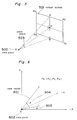
- An image displaying system comprising:a view vector memory portion (15) for maintaining a 3-dimensional portion of a viewpoint and a 3-dimensional angle data indicating an existing view vector direction in a 3-dimensional space;a screen position inputting portion (11) for interactively inputting a target point which is a 2-dimensional position on a display screen indicating a new vector direction; anda view vector direction computing portion (14) which computes the 3-dimensional angle data indicating the new view vector direction from an existing screen base position on the display screen indicating the existing view vector direction, the target point inputted from the screen position inputting portion, the 3-dimensional position of the viewpoint read from the view vector memory portion, and the 3-dimensional angle data indicating the existing view vector direction read from the view vector memory portion, to thereby store the 3-dimensional angle data indicating the new view vector direction in the view vector memory portion as the new screen base position.
- The image displaying system as claimed in claim 1,
further comprising an interpolated position computing portion (12) which is interposed between the screen position inputting portion (11) and the view vector direction computing portion (14), for producing 2-dimensional sample target points by sampling a curve interpolated from the target points fed from the screen position inputting portion (11).
Applications Claiming Priority (4)
| Application Number | Priority Date | Filing Date | Title |
|---|---|---|---|
| JP97968/90 | 1990-04-13 | ||
| JP2097968A JP2584100B2 (en) | 1990-04-13 | 1990-04-13 | Image display device |
| JP100020/90 | 1990-04-16 | ||
| JP10002090A JP2616132B2 (en) | 1990-04-16 | 1990-04-16 | Image display device |
Publications (3)
| Publication Number | Publication Date |
|---|---|
| EP0451875A2 EP0451875A2 (en) | 1991-10-16 |
| EP0451875A3 EP0451875A3 (en) | 1993-05-12 |
| EP0451875B1 true EP0451875B1 (en) | 1998-11-04 |
Family
ID=26439095
Family Applications (1)
| Application Number | Title | Priority Date | Filing Date |
|---|---|---|---|
| EP91105969A Expired - Lifetime EP0451875B1 (en) | 1990-04-13 | 1991-04-15 | Image displaying system |
Country Status (4)
| Country | Link |
|---|---|
| US (1) | US5325472A (en) |
| EP (1) | EP0451875B1 (en) |
| CA (1) | CA2040273C (en) |
| DE (1) | DE69130432T2 (en) |
Families Citing this family (78)
| Publication number | Priority date | Publication date | Assignee | Title |
|---|---|---|---|---|
| JP2892423B2 (en) * | 1990-02-28 | 1999-05-17 | 株式会社日立製作所 | Image display device and image display method |
| JP2719056B2 (en) * | 1991-08-20 | 1998-02-25 | 富士通株式会社 | 3D object drawing device |
| JP3137245B2 (en) * | 1991-10-30 | 2001-02-19 | ソニー株式会社 | Free curve creation method and free curved surface creation method |
| US5734384A (en) * | 1991-11-29 | 1998-03-31 | Picker International, Inc. | Cross-referenced sectioning and reprojection of diagnostic image volumes |
| US5644689A (en) * | 1992-01-13 | 1997-07-01 | Hitachi, Ltd. | Arbitrary viewpoint three-dimensional imaging method using compressed voxel data constructed by a directed search of voxel data representing an image of an object and an arbitrary viewpoint |
| IL106410A (en) * | 1992-08-06 | 1996-09-12 | Hughes Training Inc | Interactive computerized witness interrogation recording tool |
| GB9222767D0 (en) * | 1992-10-30 | 1992-12-09 | Canon Res Ct Europe Ltd | Processing image data |
| US5684937A (en) * | 1992-12-14 | 1997-11-04 | Oxaal; Ford | Method and apparatus for performing perspective transformation on visible stimuli |
| JP3151079B2 (en) * | 1993-04-05 | 2001-04-03 | 日本電信電話株式会社 | How to remove animation aliasing |
| JPH0778267A (en) * | 1993-07-09 | 1995-03-20 | Silicon Graphics Inc | Method for display of shadow and computer-controlled display system |
| JPH0757117A (en) * | 1993-07-09 | 1995-03-03 | Silicon Graphics Inc | Forming method of index to texture map and computer control display system |
| EP0641993B1 (en) * | 1993-09-03 | 1999-06-30 | Canon Kabushiki Kaisha | Shape measuring apparatus |
| DE4341367C1 (en) * | 1993-12-04 | 1995-06-14 | Harald Dr Med Dr Med Eufinger | Process for the production of endoprostheses |
| US5511157A (en) * | 1993-12-13 | 1996-04-23 | International Business Machines Corporation | Connection of sliders to 3D objects to allow easy user manipulation and viewing of objects |
| US5694530A (en) * | 1994-01-18 | 1997-12-02 | Hitachi Medical Corporation | Method of constructing three-dimensional image according to central projection method and apparatus for same |
| US5900878A (en) * | 1994-01-18 | 1999-05-04 | Hitachi Medical Corporation | Method of constructing pseudo-three-dimensional image for obtaining central projection image through determining view point position by using parallel projection image and apparatus for displaying projection image |
| US5790950A (en) * | 1994-03-18 | 1998-08-04 | Fujitsu Limited | Computer graphics apparatus having an improved walk-through function |
| US5530774A (en) * | 1994-03-25 | 1996-06-25 | Eastman Kodak Company | Generation of depth image through interpolation and extrapolation of intermediate images derived from stereo image pair using disparity vector fields |
| WO1996003717A1 (en) * | 1994-07-22 | 1996-02-08 | Apple Computer, Inc. | Method and system for the placement of texture on three-dimensional objects |
| FR2724033B1 (en) * | 1994-08-30 | 1997-01-03 | Thomson Broadband Systems | SYNTHESIS IMAGE GENERATION METHOD |
| JPH0896165A (en) * | 1994-09-29 | 1996-04-12 | Fujitsu Ltd | Method and device for image generation |
| JPH08115439A (en) * | 1994-10-13 | 1996-05-07 | Canon Inc | Picture data processor and picture reproduction device |
| WO1996024216A1 (en) | 1995-01-31 | 1996-08-08 | Transcenic, Inc. | Spatial referenced photography |
| JPH09153146A (en) * | 1995-09-28 | 1997-06-10 | Toshiba Corp | Virtual space display method |
| US6426757B1 (en) | 1996-03-04 | 2002-07-30 | International Business Machines Corporation | Method and apparatus for providing pseudo-3D rendering for virtual reality computer user interfaces |
| DE69734747T2 (en) * | 1996-03-22 | 2006-07-27 | Canon K.K. | Method and device for image processing |
| TW346611B (en) * | 1996-03-28 | 1998-12-01 | Sega Enterprises Kk | An image processor, a game machine using the image processor, a method of image processing and a medium |
| IL119928A (en) * | 1996-12-29 | 2001-01-11 | Univ Ramot | Model-based view extrapolation for interactive virtual reality systems |
| US6104406A (en) * | 1997-04-04 | 2000-08-15 | International Business Machines Corporation | Back away navigation from three-dimensional objects in three-dimensional workspace interactive displays |
| US5982375A (en) * | 1997-06-20 | 1999-11-09 | Sun Microsystems, Inc. | Floating point processor for a three-dimensional graphics accelerator which includes single-pass stereo capability |
| US20020036617A1 (en) | 1998-08-21 | 2002-03-28 | Timothy R. Pryor | Novel man machine interfaces and applications |
| US6720949B1 (en) | 1997-08-22 | 2004-04-13 | Timothy R. Pryor | Man machine interfaces and applications |
| US6750848B1 (en) * | 1998-11-09 | 2004-06-15 | Timothy R. Pryor | More useful man machine interfaces and applications |
| US20030158786A1 (en) * | 1999-02-26 | 2003-08-21 | Skyline Software Systems, Inc. | Sending three-dimensional images over a network |
| US7015950B1 (en) | 1999-05-11 | 2006-03-21 | Pryor Timothy R | Picture taking method and apparatus |
| US7328119B1 (en) * | 2000-03-07 | 2008-02-05 | Pryor Timothy R | Diet and exercise planning and motivation including apparel purchases based on future appearance |
| US8306635B2 (en) | 2001-03-07 | 2012-11-06 | Motion Games, Llc | Motivation and enhancement of physical and mental exercise, rehabilitation, health and social interaction |
| US8300042B2 (en) * | 2001-06-05 | 2012-10-30 | Microsoft Corporation | Interactive video display system using strobed light |
| US7259747B2 (en) * | 2001-06-05 | 2007-08-21 | Reactrix Systems, Inc. | Interactive video display system |
| US8035612B2 (en) * | 2002-05-28 | 2011-10-11 | Intellectual Ventures Holding 67 Llc | Self-contained interactive video display system |
| JP3594915B2 (en) * | 2001-08-03 | 2004-12-02 | 株式会社ナムコ | PROGRAM, INFORMATION STORAGE MEDIUM, AND GAME DEVICE |
| US7539606B2 (en) * | 2001-11-15 | 2009-05-26 | Nintendo Co. Ltd. | System and method for efficiently simulating and imaging realistic water surface and other effects |
| US7710391B2 (en) * | 2002-05-28 | 2010-05-04 | Matthew Bell | Processing an image utilizing a spatially varying pattern |
| US7170492B2 (en) * | 2002-05-28 | 2007-01-30 | Reactrix Systems, Inc. | Interactive video display system |
| US7348963B2 (en) * | 2002-05-28 | 2008-03-25 | Reactrix Systems, Inc. | Interactive video display system |
| AU2003301043A1 (en) | 2002-12-13 | 2004-07-09 | Reactrix Systems | Interactive directed light/sound system |
| US7576727B2 (en) * | 2002-12-13 | 2009-08-18 | Matthew Bell | Interactive directed light/sound system |
| US7619626B2 (en) * | 2003-03-01 | 2009-11-17 | The Boeing Company | Mapping images from one or more sources into an image for display |
| US7148861B2 (en) * | 2003-03-01 | 2006-12-12 | The Boeing Company | Systems and methods for providing enhanced vision imaging with decreased latency |
| US7164423B1 (en) | 2003-04-30 | 2007-01-16 | Apple Computer, Inc. | Method and apparatus for providing an animated representation of a reorder operation |
| WO2005041579A2 (en) | 2003-10-24 | 2005-05-06 | Reactrix Systems, Inc. | Method and system for processing captured image information in an interactive video display system |
| US20050088407A1 (en) | 2003-10-24 | 2005-04-28 | Matthew Bell | Method and system for managing an interactive video display system |
| EP1766552A2 (en) * | 2004-06-23 | 2007-03-28 | Strider Labs, Inc. | System and method for 3d object recognition using range and intensity |
| US9128519B1 (en) | 2005-04-15 | 2015-09-08 | Intellectual Ventures Holding 67 Llc | Method and system for state-based control of objects |
| US8081822B1 (en) | 2005-05-31 | 2011-12-20 | Intellectual Ventures Holding 67 Llc | System and method for sensing a feature of an object in an interactive video display |
| US7925391B2 (en) * | 2005-06-02 | 2011-04-12 | The Boeing Company | Systems and methods for remote display of an enhanced image |
| JP4691158B2 (en) * | 2005-06-16 | 2011-06-01 | ストライダー ラブス,インコーポレイテッド | Recognition system and method for 2D images using 3D class model |
| US8098277B1 (en) | 2005-12-02 | 2012-01-17 | Intellectual Ventures Holding 67 Llc | Systems and methods for communication between a reactive video system and a mobile communication device |
| US7403833B2 (en) * | 2006-04-03 | 2008-07-22 | Stratasys, Inc. | Method for optimizing spatial orientations of computer-aided design models |
| US8300798B1 (en) | 2006-04-03 | 2012-10-30 | Wai Wu | Intelligent communication routing system and method |
| US8050786B2 (en) * | 2007-07-11 | 2011-11-01 | Stratasys, Inc. | Method for building three-dimensional objects with thin wall regions |
| EP2188737A4 (en) | 2007-09-14 | 2011-05-18 | Intellectual Ventures Holding 67 Llc | Processing of gesture-based user interactions |
| US8159682B2 (en) | 2007-11-12 | 2012-04-17 | Intellectual Ventures Holding 67 Llc | Lens system |
| US8127235B2 (en) | 2007-11-30 | 2012-02-28 | International Business Machines Corporation | Automatic increasing of capacity of a virtual space in a virtual world |
| US20090164919A1 (en) | 2007-12-24 | 2009-06-25 | Cary Lee Bates | Generating data for managing encounters in a virtual world environment |
| US20100039500A1 (en) * | 2008-02-15 | 2010-02-18 | Matthew Bell | Self-Contained 3D Vision System Utilizing Stereo Camera and Patterned Illuminator |
| US8259163B2 (en) | 2008-03-07 | 2012-09-04 | Intellectual Ventures Holding 67 Llc | Display with built in 3D sensing |
| US8595218B2 (en) | 2008-06-12 | 2013-11-26 | Intellectual Ventures Holding 67 Llc | Interactive display management systems and methods |
| EP2261827B1 (en) * | 2009-06-10 | 2015-04-08 | Dassault Systèmes | Process, program and apparatus for displaying an assembly of objects of a PLM database |
| US8725476B1 (en) * | 2010-05-04 | 2014-05-13 | Lucasfilm Entertainment Company Ltd. | Applying details in a simulation |
| US8970592B1 (en) | 2011-04-19 | 2015-03-03 | Lucasfilm Entertainment Company LLC | Simulating an arbitrary number of particles |
| FR2980005A1 (en) * | 2011-09-09 | 2013-03-15 | Movea | METHOD FOR CONTROLLING A CURSOR BY ATTITUDE MEASUREMENTS OF A POINTER AND POINTER USING THE SAME |
| US9785610B1 (en) * | 2011-11-15 | 2017-10-10 | Hunter Engineering Company | Visual display of vehicle wheel assembly for vehicle wheel service system |
| CN102542868B (en) * | 2012-01-09 | 2014-03-19 | 中国人民解放军空军军训器材研究所 | Visual simulation method and device |
| CN105354820B (en) * | 2015-09-30 | 2018-05-22 | 深圳多新哆技术有限责任公司 | Adjust the method and device of virtual reality image |
| US10217283B2 (en) * | 2015-12-17 | 2019-02-26 | Google Llc | Navigation through multidimensional images spaces |
| CN111161428B (en) * | 2019-12-13 | 2023-04-11 | 深圳大学 | Three-dimensional map vector tile data generation method, storage medium and terminal |
| CN112546626B (en) * | 2020-12-09 | 2024-03-26 | 杭州电魂网络科技股份有限公司 | Object display method and device combined with lamplight, electronic equipment and storage medium |
Family Cites Families (2)
| Publication number | Priority date | Publication date | Assignee | Title |
|---|---|---|---|---|
| DE3587638T2 (en) * | 1984-07-20 | 1994-06-01 | Tektronix Inc | Spherical swiveling method and device. |
| US4734690A (en) * | 1984-07-20 | 1988-03-29 | Tektronix, Inc. | Method and apparatus for spherical panning |
-
1991
- 1991-04-11 CA CA002040273A patent/CA2040273C/en not_active Expired - Lifetime
- 1991-04-12 US US07/684,389 patent/US5325472A/en not_active Expired - Lifetime
- 1991-04-15 EP EP91105969A patent/EP0451875B1/en not_active Expired - Lifetime
- 1991-04-15 DE DE69130432T patent/DE69130432T2/en not_active Expired - Fee Related
Also Published As
| Publication number | Publication date |
|---|---|
| US5325472A (en) | 1994-06-28 |
| DE69130432T2 (en) | 1999-07-08 |
| DE69130432D1 (en) | 1998-12-10 |
| CA2040273C (en) | 1995-07-18 |
| EP0451875A3 (en) | 1993-05-12 |
| CA2040273A1 (en) | 1991-10-14 |
| EP0451875A2 (en) | 1991-10-16 |
Similar Documents
| Publication | Publication Date | Title |
|---|---|---|
| EP0451875B1 (en) | Image displaying system | |
| KR0156052B1 (en) | Texture mapping method and apparatus | |
| US6426757B1 (en) | Method and apparatus for providing pseudo-3D rendering for virtual reality computer user interfaces | |
| US7382374B2 (en) | Computerized method and computer system for positioning a pointer | |
| US20090153555A1 (en) | System and Computer-Implemented Method for Modeling the Three-Dimensional Shape of An Object by Shading of a Two-Dimensional Image of the Object | |
| US6724383B1 (en) | System and computer-implemented method for modeling the three-dimensional shape of an object by shading of a two-dimensional image of the object | |
| JPH07254072A (en) | Texture mapping method and device therefor | |
| JPH10198822A (en) | Image compositing device | |
| EP0714057B1 (en) | Method and apparatus for displaying a cursor along a two dimensional representation of a computer generated three dimensional surface | |
| JPH0434159B2 (en) | ||
| KR100381817B1 (en) | Generating method of stereographic image using Z-buffer | |
| EP0817133B1 (en) | Object visualization in context | |
| US6346939B1 (en) | View dependent layer ordering method and system | |
| KR100559127B1 (en) | Image processing device | |
| KR100429092B1 (en) | Graphic image processing method and apparatus | |
| KR950025512A (en) | Hardware-based graphical workstation solution for refraction | |
| EP1111546B1 (en) | Display techniques for three-dimensional virtual reality | |
| JPH0721752B2 (en) | Multi-window display method | |
| JPH0634219B2 (en) | Three-dimensional projection image display device | |
| EP1720090B1 (en) | Computerized method and computer system for positioning a pointer | |
| CA2282240C (en) | System and computer-implemented method for modeling the three-dimensional shape of an object by shading of a two-dimensional image of the object | |
| JP3132220B2 (en) | 3D model shape creation method | |
| FI108679B (en) | A 3D graphics arrangement | |
| JP2584100B2 (en) | Image display device | |
| JPH0296291A (en) | Display device |
Legal Events
| Date | Code | Title | Description |
|---|---|---|---|
| PUAI | Public reference made under article 153(3) epc to a published international application that has entered the european phase |
Free format text: ORIGINAL CODE: 0009012 |
|
| 17P | Request for examination filed |
Effective date: 19910415 |
|
| AK | Designated contracting states |
Kind code of ref document: A2 Designated state(s): DE FR |
|
| PUAL | Search report despatched |
Free format text: ORIGINAL CODE: 0009013 |
|
| AK | Designated contracting states |
Kind code of ref document: A3 Designated state(s): DE FR |
|
| 17Q | First examination report despatched |
Effective date: 19961209 |
|
| GRAG | Despatch of communication of intention to grant |
Free format text: ORIGINAL CODE: EPIDOS AGRA |
|
| GRAG | Despatch of communication of intention to grant |
Free format text: ORIGINAL CODE: EPIDOS AGRA |
|
| GRAH | Despatch of communication of intention to grant a patent |
Free format text: ORIGINAL CODE: EPIDOS IGRA |
|
| GRAH | Despatch of communication of intention to grant a patent |
Free format text: ORIGINAL CODE: EPIDOS IGRA |
|
| GRAA | (expected) grant |
Free format text: ORIGINAL CODE: 0009210 |
|
| AK | Designated contracting states |
Kind code of ref document: B1 Designated state(s): DE FR |
|
| REF | Corresponds to: |
Ref document number: 69130432 Country of ref document: DE Date of ref document: 19981210 |
|
| ET | Fr: translation filed | ||
| PLBE | No opposition filed within time limit |
Free format text: ORIGINAL CODE: 0009261 |
|
| STAA | Information on the status of an ep patent application or granted ep patent |
Free format text: STATUS: NO OPPOSITION FILED WITHIN TIME LIMIT |
|
| 26N | No opposition filed | ||
| PGFP | Annual fee paid to national office [announced via postgrant information from national office to epo] |
Ref country code: FR Payment date: 20090417 Year of fee payment: 19 Ref country code: DE Payment date: 20090409 Year of fee payment: 19 |
|
| REG | Reference to a national code |
Ref country code: FR Ref legal event code: ST Effective date: 20101230 |
|
| PG25 | Lapsed in a contracting state [announced via postgrant information from national office to epo] |
Ref country code: DE Free format text: LAPSE BECAUSE OF NON-PAYMENT OF DUE FEES Effective date: 20101103 |
|
| PG25 | Lapsed in a contracting state [announced via postgrant information from national office to epo] |
Ref country code: FR Free format text: LAPSE BECAUSE OF NON-PAYMENT OF DUE FEES Effective date: 20100430 |