EP0180226B1 - Grip device - Google Patents
Grip device Download PDFInfo
- Publication number
- EP0180226B1 EP0180226B1 EP85113876A EP85113876A EP0180226B1 EP 0180226 B1 EP0180226 B1 EP 0180226B1 EP 85113876 A EP85113876 A EP 85113876A EP 85113876 A EP85113876 A EP 85113876A EP 0180226 B1 EP0180226 B1 EP 0180226B1
- Authority
- EP
- European Patent Office
- Prior art keywords
- workpiece
- piezoelectric elements
- bimorph type
- type piezoelectric
- voltage
- Prior art date
- Legal status (The legal status is an assumption and is not a legal conclusion. Google has not performed a legal analysis and makes no representation as to the accuracy of the status listed.)
- Expired
Links
- 210000000078 claw Anatomy 0.000 claims description 39
- 230000000087 stabilizing effect Effects 0.000 claims description 7
- 239000003990 capacitor Substances 0.000 claims description 6
- 230000000881 depressing effect Effects 0.000 claims 2
- 238000001514 detection method Methods 0.000 description 12
- 238000010586 diagram Methods 0.000 description 4
- 210000000707 wrist Anatomy 0.000 description 4
- 239000000428 dust Substances 0.000 description 3
- 238000005452 bending Methods 0.000 description 2
- 230000010287 polarization Effects 0.000 description 2
- 239000002131 composite material Substances 0.000 description 1
- 238000006073 displacement reaction Methods 0.000 description 1
- 230000002265 prevention Effects 0.000 description 1
Images



Classifications
-
- G—PHYSICS
- G01—MEASURING; TESTING
- G01L—MEASURING FORCE, STRESS, TORQUE, WORK, MECHANICAL POWER, MECHANICAL EFFICIENCY, OR FLUID PRESSURE
- G01L5/00—Apparatus for, or methods of, measuring force, work, mechanical power, or torque, specially adapted for specific purposes
- G01L5/22—Apparatus for, or methods of, measuring force, work, mechanical power, or torque, specially adapted for specific purposes for measuring the force applied to control members, e.g. control members of vehicles, triggers
- G01L5/226—Apparatus for, or methods of, measuring force, work, mechanical power, or torque, specially adapted for specific purposes for measuring the force applied to control members, e.g. control members of vehicles, triggers to manipulators, e.g. the force due to gripping
-
- B—PERFORMING OPERATIONS; TRANSPORTING
- B25—HAND TOOLS; PORTABLE POWER-DRIVEN TOOLS; MANIPULATORS
- B25J—MANIPULATORS; CHAMBERS PROVIDED WITH MANIPULATION DEVICES
- B25J13/00—Controls for manipulators
- B25J13/08—Controls for manipulators by means of sensing devices, e.g. viewing or touching devices
- B25J13/081—Touching devices, e.g. pressure-sensitive
- B25J13/082—Grasping-force detectors
-
- G—PHYSICS
- G01—MEASURING; TESTING
- G01L—MEASURING FORCE, STRESS, TORQUE, WORK, MECHANICAL POWER, MECHANICAL EFFICIENCY, OR FLUID PRESSURE
- G01L1/00—Measuring force or stress, in general
- G01L1/16—Measuring force or stress, in general using properties of piezoelectric devices
-
- Y—GENERAL TAGGING OF NEW TECHNOLOGICAL DEVELOPMENTS; GENERAL TAGGING OF CROSS-SECTIONAL TECHNOLOGIES SPANNING OVER SEVERAL SECTIONS OF THE IPC; TECHNICAL SUBJECTS COVERED BY FORMER USPC CROSS-REFERENCE ART COLLECTIONS [XRACs] AND DIGESTS
- Y10—TECHNICAL SUBJECTS COVERED BY FORMER USPC
- Y10S—TECHNICAL SUBJECTS COVERED BY FORMER USPC CROSS-REFERENCE ART COLLECTIONS [XRACs] AND DIGESTS
- Y10S294/00—Handling: hand and hoist-line implements
- Y10S294/907—Sensor controlled device
-
- Y—GENERAL TAGGING OF NEW TECHNOLOGICAL DEVELOPMENTS; GENERAL TAGGING OF CROSS-SECTIONAL TECHNOLOGIES SPANNING OVER SEVERAL SECTIONS OF THE IPC; TECHNICAL SUBJECTS COVERED BY FORMER USPC CROSS-REFERENCE ART COLLECTIONS [XRACs] AND DIGESTS
- Y10—TECHNICAL SUBJECTS COVERED BY FORMER USPC
- Y10S—TECHNICAL SUBJECTS COVERED BY FORMER USPC CROSS-REFERENCE ART COLLECTIONS [XRACs] AND DIGESTS
- Y10S310/00—Electrical generator or motor structure
- Y10S310/80—Piezoelectric polymers, e.g. PVDF
Definitions
- the present invention relates to the grip device of a robot or manipulator for handling a workpiece.
- a prior-art grip device installed on a robot or manipulator is of the type which grasps a workpiece with a fixed force. With the prior-art grip device, therefore, the property of the workpiece has sometimes made it difficult to exactly grasp the workpiece.
- the measure of mounting a force sensor on the fingers of the grip device is taken.
- the grip device When it is intended to sensitively control the grip device relative to the workpiece, the grip device must be furnished with a large number of sensors including a pressure sensor, an ultrasonic wave sensor, etc., besides the aforementioned force sensor. Such attachment of the large number of sensors to the fingers of the grip device renders the structure of the grip device itself large and complicated, and might degrade the reliability due to the insufficient management of the sensors.
- An object of the present invention is to provide a grip device employing bimorph type piezoelectric elements which can be sensitively positioned to a workpiece.
- Another object of the present invention is to provide a grip device employing bimorph type piezoelectric elements which can be used in a clean atmosphere such as clean room that should be free from dust.
- the present invention for accomplishing the object consists of a grip device wherein bimorph type piezoelectric elements are employed as fingers for grasping a workpiece, in a grip device comprising bimorph type piezoelectric elements which are mounted on a grip body and which form at leust one pair of fingers, a voltage feed circuit which is connected to said piezoelectric elements in order to bend and deform them, and means connected to an output side end of said piezoelectric elements to control a grasping force for the workpiece of the basis of an output signal thereof, whereby said piezoelectric elements forming the fingers are permitted to perform a workpiece grasping operation and at least one sensor function without mounting any additional sensor.
- the present invention for accomplishing the object consists, in a grip device wherein bimorph type piezoelectric elements are employed as fingers for grasping a workpiece, in a grip device comprising a grip body, first bimorph type piezoelectric elements which are mounted on said grip body in opposition to each other, a claw for grasping a workpiece, which is attached to a fore end of said each first bimorph type piezoelectric element, a second bimorph type piezoelectric element which is mounted on said grip body, a claw for stabilizing the grasp of the workpeice, which is attached to a fore end of said second bimorph type piezoelectric element, a voltage feed circuit which is connected to said first and second bimorph type piezoelectric elements in order to bend and deform them, and means connected to an output side end of said second bimorph type piezoelectric element to control a grasping force for the workpiece on the basis of an output signal thereof.
- Fig. 1 shows an example of a robot which is furnished with an example of a grip device according to the present invention.
- numeral 1 designates a base, numeral 2 a swivel body which is turnably mounted on the base 1, numeral 3 a first arm which is rotatably mounted on the swivel body 2, numeral 4 a second arm which is rotatably mounted on the first arm 3, numeral 5 an auxiliary arm, numeral 6 a wrist which is mounted on the front end of the second arm 4, and numeral 7 the grip device which is installed on the wrist 6.
- This grip device 7 is composed of a grip body 8 which is attached to the aforementioned wrist 6, and fingers 9 which are formed by a pair of bimorph type piezoelectric elements mounted on the grip body 8.
- Each of the pair of fingers 9 is constructed of two piezoelectric elements 9A and 9B which are joined so as to oppose the polarization directions (indicated by arrows B) thereof (hereinbelow, termed the "series type").
- a voltage feed circuit 10 for effectuating the actuator function
- a workpiece presence discriminating circuit 20 for effectuating the sensor function
- a workpiece touch detecting circuit 30 Connected to the pair of fingers 9 are a voltage feed circuit 10 for effectuating the actuator function, a workpiece presence discriminating circuit 20 for effectuating the sensor function, and a workpiece touch detecting circuit 30.
- Numeral 40 in Fig. 2 designates a control circuit for the robot.
- the voltage feed circuit 10 deforms the fingers 9 constructed of the bimorph type piezoelectric elements in the directions of grasping a workpiece, and controls the grasping force thereof to a set value.
- Numeral 101 indicates a power source unit which applies a D.C. voltage to the bimorph type piezoelectric elements 9A, 9B forming the pair of fingers 9, and the output voltage of which can be adjusted.
- Numeral 102 indicates a variable frequency oscillator which is connected to the bimorph type piezoelectric elements 9A, 9B of one finger 9. A frequency signal from this variable frequency oscillator 102 is applied to the bimorph type piezoelectric elements 9A, 9B of one finger in order to detect as external force acting on the finger 9.
- These bimorph type piezoelectric elements 9A, 9B of one finger are connected in parallel with a resistor 103. Further, they are bridge-connected to a capacitor 104 and a resistor 105, the capacitor having a capacitance which is substantially equal to the capacitance of the piezoelectric elements 9A, 9B.
- the resistor 103 and the resistor 105 are set at equal impedances.
- Rectifier circuits 106 and 107 are respectively connected across both the terminals of the resistors 103 and 105 to convert the corresponding terminal voltages into D.C. voltages.
- These recitifer circuits 106, 107 are connected to a differential amplifier 108.
- This differential amplifier 108 evaluates the difference between the output voltages from the rectifier circuits 106, 107, and controls the frequency of the variable frequency oscillator 102 so as to make the difference zero.
- a frequency detector 109 Connected to the terminals of the variable frequency oscillator 102 is a frequency detector 109 which detects a frequency variation.
- the frequency variation detected by the frequency detector 109 is delivered to a function generator 110 and a comparator 111.
- the function generator 110 provides an acting external force W on the basis of the detected frequency variation Af. The relationship between the frequency variation Af and the external force W will be described later.
- the external force W from the function generator 110 is displayed on a display unit 112.
- the comparator 111 controls the output voltage of the power source unit 101 on the basis of the voltage of the frequency variation from the frequency detector 109 and a reference voltage corresponding to a set grasping force from a reference voltage setting unit 113, thereby to control the grasping force of the fingers 9 to the set value.
- Fig. 3 shows the frequency characteristics of the bimorph type piezoelectric element for use in the present invention.
- the axis of abscissas represents the frequency F
- the axis of ordinates the impedance Z of the piezoelectric element.
- a curve X in the figure shows the characteristic which is exhibited when no external force acts on the piezoelectric element
- a curve Y the characteristic which is exhibited when an external force acts on the piezoelectric element.
- a straight line X' shows the frequency characteristic of a capacitor having the same capacitance as that of the piezoelectric element. Letting w denote the angular frequency and C denote the capacitance of the capacitor, the frequency characteristic is expressed by 1/wC.
- the impedances Z agree at a point A x .
- the impedance Z at this time is let be Z AX , and the frequency F is let be f " .
- the impedance Z changes in accordance with the curve Y, to a value Z AY corresponding to a point Ay on this curve Y. That is, the impedance Z changes from Z AX to Z AY .
- both the impedances Z agree at a point By when this frequency has become f e .
- the external force W acting on the piezoelectric element namely, the grasping force can be known by knowing the frequency change Af at this time.
- the relationship between the frequency change Af and the external force W has a very good linearity as shown in Fig. 4. This relationship is set in the foregoing function generator 110.
- the voltage feed circuit 10 controls the grip of the pair of fingers 9 and has the functon of detecting the grasping force.
- the workpiece presence discriminating circuit 20 disciminates the presence or absence of a workpiece with no contact, using one of the paired fingers 9 moved to workpiece grasping positions as an oscillating side and the other as a receiving side likewise to an ultrasonic wave sensor.
- a frequency oscillator 203 is connected to one finger 9 through switches 201 and 202.
- a voltage detector 206 is connected to the other finger 9 through switches 204 and 205. This voltage detector 206 detects a generated voltage based on the vibrations of the other finger 9 which are induced by the vibrations of one finger 9, and the detected voltage value is delivered to a discrimination circuit 207.
- the discrimination circuit 207 evaluates the difference AV between the voltage value V A from the voltage detector 206 and the induced voltage V o of the piezoelectric element for the absence of the workpiece, set in a reference voltage generator 208. Thus, it judges the presence of the workpiece between the fingers 9 when a value (AVN O ) obtained by dividing the difference voltage AV by the induced voltage V o is greater than a set value, and it judges the absence of the workpiece between the fingers 9 when the value is less than the set value.
- the discrimination circuit 207 controls a switch changer 209 to an open position and delivers, for example, a grip operation stopping command to the robot control circuit 40.
- the relationship between the moved distance L of the workpiece A along the fingers 9 and the voltage ratio AVN O becomes a characteristic illustrated in Fig. 6.
- the ⁇ V/V 0 value corresponding to a position L, at which the fingers 9 can reliably grasp the workpiece A becomes A 1 , so that the value A, is set as the reference voltage set value of the discrimination circuit 207.
- the value ⁇ V/V 0 is greater than the set value, the presence of the workpiece A between the fingers 9 can be discriminated, and when it is less than, the absence of the workpiece A between the fingers 9 can be discriminated in non-contacting fashion.
- the workpiece touch detecting circuit 30 senses that the fingers 9 have touched the workpiece.
- Pulse detectors 301 and 302 are respectively connected to the fingers 9 to detect pulsative voltage changes which arise when the fingers 9 have touched the workpiece.
- These pulse detectors 301 and 302 are connected to a direction discriminating circuit 303 which discriminates the moving direction of the arm of the robot.
- the direction discriminating circuit 303 supplies the robot control circuit 40 with a signal of the moving direction of the robot arm relative to the workpiece in order to accurately position the finger 9 to the workpiece.
- the robot control circuit 40 operates to control the arm of the robot so as to accurately position the finger 9 to the workpiece.
- the arms of the robot are controlled by the control circuit 40 of the robot until the fingers 9 constructed of the piezoelectric elements are positioned to a position corresponding to the workpiece.
- the switches 201-205 are changed by the switch changer 209, and the frequency from the frequency oscillator 203 is applied to one finger 9 to vibrate this finger 9.
- the vibrations of this finger 9 propagate in the air, and vibrate the other finger 9.
- a voltage is generated across the terminals of the other finger 9 by the vibrations.
- the voltage is detected by the voltage detector 206, and is input to the discrimination circuit 207,On the basis of the characteristic shown in Fig.
- the discrimination circuit 207 discriminates the existence of the workpiece A between the fingers 9. In a case where it is less than A 1 , the circuit 207 discriminates the nonexistance of the workpiece A between the fingers 9 and supplies the robot control circuit 40 with a robot operation stopping command or a grip operation stopping command.
- the discrimination circuit 20 controls the changer 209 to change the switches 201-205 to their original positions.
- a voltage is applied to one finger 9 by the voltage feed circuit 10, to bend and deform the fingers 9 inwards relative to each other and to start a grasping operation.
- the fingers 9 undergo bending deformations with minute vibrations based on the frequency from the variable frequency oscillator 102.
- the robot control circuit 40 controls the fingers 9 on the basis of known information such as the widthwise dimension between the pair of fingers 9, so that the workpiece A is positioned between ths fingers 9, while the fingers 9 can reliably grasp the workpiece A owing to the grap control circuit 10.
- the workpiece can be exactly positioned and grasped.
- the fingers constructed of the piezoelectric elements are not furnished with any sensors, and the operation circuits and the sensor function circuits are switched in sequence, whereby for example, the grasping operation being the actuator function and a single operation selected from or a composite operation combining the detection of a grasping force, the non-contacting detection of the presence or absence of the workpiece and the adjustment of the relative position between the fingers and the workpiece, being the sensor functions, become possible, and a safe and highly reliable grasping operation can be performed.
- the grasping force 80 gf can be attained in a case where the fingers 9 are constructed of piezoelectric elements 20 mm long, 7 mm wide and 0.5 mm thick.
- Fig. 7 While the foregoing embodiment has fixed the grasping interval of the pair of fingers 9, an arrangement is also possible wherein, as shown in Fig. 7, two fingers 9 formed by piezoelectric elements are respectively mounted on holders 51, the holders 51 are held in engagement with a guide shaft 52 and a threaded shaft 53 disposed in a grip body 8, a motor 54 is connected to the threaded shaft 53, and the interval of the pair of fingers 9 can be varied by the rotation of the motor 54. With this arrangement, various workpieces can be grasped. Moreover, the piezo- electric elements forming the pair of fingers 9 may well be arranged in the so-called parallel type in which they are joined with their polarization directions held identical as illustrated in Fig. 8. It is also possible to dispose a plurality of pairs of fingers 9.
- a grip portion can be sensitively positioned, and the workpiece can be exactly grasped.
- Fig. 9 shows still another embodiment of the grip device of the present invention.
- each of bimorph type piezoelectric elements 91 and 91' has one end thereof fixed to a grip body 90.
- Grip claws 92 and 92' for grasping a workpiece A are attached to the other ends of the respective piezeoelectric elements 91 and 91'.
- the grip body 90 is provided with a grip stabilizing claw 93. This claw 93 is driven by a bimorph type piezoelectric element 95 one end of which is fixed by a support 94.
- the grip device of the present invention thus constructed is mounted on the front end of the wrist 6 of a robot, and performs the grasping operation in cooperation with the operation of the robot proper.
- Numerals 96 and 96' designate covers, which are intended to protect the bimorph type piezoelectric elements 91 and 91'.
- Fig. 10 shows an example of a driver circuit for grip claws 92 and 92' which constitute another embodiment of the grip device of the present invention shown in Fig. 9.
- two D.C. voltage sources 100A and 100B are connected to bimorph type piezoelectric elements 91 and 91' through switches 101. Since, owing to such an arrangement, voltages of opposite polarities can be applied to the respective piezoelectric elements 91 and 91', these piezoelectric elements 91 and 91' displace the grip claws 92 and 92' in the direction of nipping a workpiece A or in the direction of releasing it. In a case where no voltage is externally applied to the piezoelectric elements 91 and 91', no deformation arises.
- the grip claws 92 and 92' are in states indicated by solid lines.
- the grip claws are displaced as indicated by broken lines.
- the grip claws 92 and 92' become opposite in direction.
- the grip claws 92 and 92' are moved to a workpiece grasping position in the states of the broken lines in Fig. 10, and the polarities of the applied voltages are thereafter reversed, whereby the workpiece A can be grasped.
- Fig. 11 shows an example of a driver circuit for a grip stabilizing claw 93 which is used for still another embodiment of the device of the present invention shown in Fig. 9.
- the grip stabilizing claw 93 operates to as to depress or release a workpiece A, depending upon the polarity of a voltage which is applied to a bimorph type piezoelectric element 95.
- This bimorph type piezoelectric element 95 has a sensor function for detecting a grasping force, and controls the grasping force of the workpiece A. More specifically, a driver circuit composed of a power source circuit 130 for directly affording a deformation and a force detection circuit 131 for detecting a pressing force is connected to the bimorph type piezoelectric element 95.
- the force detection circuit 131 detects the pressing force acting on the bimorph type piezoelectric element 95 and inputs the result to the power source circuit 130 so as to adjust the output voltage of the power source circuit 130, thereby to regulate the magnitude of deformation of the bimorph type piezoelectric element 95. Thus, a required pressing force can be attained.
- the force detection in the force detection circuit 131 is carried out according to the same principle as illustrated in Fig. 3, and shall not be repeatedly explained.
- Fig. 12 shows the movements of the claws 92, 92' and 93 constituting the device of the present invention shown in Fig. 9, in other words, the changes of the voltages applied to the respective bimorph type piezoelectric elements 91, 91' and 95, and the illustration is given as an example of an actual workpiece grasping operation.
- the axis of ordinates represents the voltage V
- a curve 20 indicates the voltage variation of the claw 93
- curves 21 and 22 indicate the circumstances of the voltage variations of the claws 91 and 91' which nip the workpiece A directly.
- the polarities of voltages applied to the bimorph type piezoelectric elements 91 and 91' which operate the claws 92 and 92' for nipping the workpiece A are opposite to each other, in the sense that the interval between these claws is wide.
- the bimorph type piezoelectric element 95 for driving the claw 93 is supplied with a voltage with which this claw is deformed to the side of the workpiece A.
- the polarities of the voltages applied to the bimorph type piezoelectric element 91 for operating the claw 92 and the bimorph type piezoelectric element 91' for driving the claw 92' are respectively changed into the opposite direction, while at the same time the voltage applied to the bimorph type piezoelectric element 95 for driving the claw 93 is changed to the opposite polarity.
- the workpiece A is nipped.
- the gradual inversion of the polarities of the voltages applied to the claws 92 and 92' is for the prevention of damages in the case where the workpiece A is fragile, and it can be suitably adjusted depending upon the properties of the workpiece A.
- a D.C. voltage with alternating current superposed thereon is applied to the bimorph type piezoelectric element 95 for driving the claw 93, to reliably hold the workpiece A from a point of time T 2 , while at the same time the force detection is executed so as to establish a predetermined pressing force.
- the robot arm 4 performs a predetermined operation. Thereafter, the workpiece A is released.
- the release can be realized by applying voltages reversely to those in the case of grasping the workpiece.
- the grip mechanism may well be furnished with means by which the interval of the claws 92 and 92' for nipping the workpiece A can be changed continuously or stepwise to fixed lengths.
- the detection of the pressing force has been applied to the control of the operation of the claw 93, it may well be simultaneously applied to the adjustment of the workpiece grasping force owing to the claws 92 and 92'.
- the structure of a slide portion forming a dust source is not included, so that a grip device free from dust which is suitable for use in a clean atmosphere such as clean room can be provided. Moreover, since a grasping force can be controlled by a force detecting mechanism, the reliable grip of a workpiece to possible and the damage thereof can be prevented. Besides, the grip device is simple in mechanism and is light in weight.
Landscapes
- Engineering & Computer Science (AREA)
- Physics & Mathematics (AREA)
- General Physics & Mathematics (AREA)
- Human Computer Interaction (AREA)
- Robotics (AREA)
- Mechanical Engineering (AREA)
- Manipulator (AREA)
Description
- The present invention relates to the grip device of a robot or manipulator for handling a workpiece.
- A prior-art grip device installed on a robot or manipulator is of the type which grasps a workpiece with a fixed force. With the prior-art grip device, therefore, the property of the workpiece has sometimes made it difficult to exactly grasp the workpiece. In order to solve the difficulty, the measure of mounting a force sensor on the fingers of the grip device is taken. When it is intended to sensitively control the grip device relative to the workpiece, the grip device must be furnished with a large number of sensors including a pressure sensor, an ultrasonic wave sensor, etc., besides the aforementioned force sensor. Such attachment of the large number of sensors to the fingers of the grip device renders the structure of the grip device itself large and complicated, and might degrade the reliability due to the insufficient management of the sensors.
- There is an example wherein the fingers of a grip device are not provided with any sensors and wherein they are constructed of bimorph type piezoelectric elements thereby to afford both a sensor function and an actuator function for a grasping operation. This example is discussed in a literature "Principle of A Piezo-Electric Micro Manipulator" by Umenani in the 8th I. S. I. R. (International Symposium on Industrial Robot) (1978). The literature reports that the generation of a grasping force of several mgf or so and the detection thereof are possible. An industrial robot, however, requires capabilities of sensitively positioning the fingers of the grip device to the workpiece as stated before and generating a great grasping force. The above grip device cannot satisfactorily demonstrate the capabilities, and cannot be applied to the industrial robot.
- An object of the present invention is to provide a grip device employing bimorph type piezoelectric elements which can be sensitively positioned to a workpiece.
- Another object of the present invention is to provide a grip device employing bimorph type piezoelectric elements which can be used in a clean atmosphere such as clean room that should be free from dust.
- The present invention for accomplishing the object consists of a grip device wherein bimorph type piezoelectric elements are employed as fingers for grasping a workpiece, in a grip device comprising bimorph type piezoelectric elements which are mounted on a grip body and which form at leust one pair of fingers, a voltage feed circuit which is connected to said piezoelectric elements in order to bend and deform them, and means connected to an output side end of said piezoelectric elements to control a grasping force for the workpiece of the basis of an output signal thereof, whereby said piezoelectric elements forming the fingers are permitted to perform a workpiece grasping operation and at least one sensor function without mounting any additional sensor.
- Further, the present invention for accomplishing the object consists, in a grip device wherein bimorph type piezoelectric elements are employed as fingers for grasping a workpiece, in a grip device comprising a grip body, first bimorph type piezoelectric elements which are mounted on said grip body in opposition to each other, a claw for grasping a workpiece, which is attached to a fore end of said each first bimorph type piezoelectric element, a second bimorph type piezoelectric element which is mounted on said grip body, a claw for stabilizing the grasp of the workpeice, which is attached to a fore end of said second bimorph type piezoelectric element, a voltage feed circuit which is connected to said first and second bimorph type piezoelectric elements in order to bend and deform them, and means connected to an output side end of said second bimorph type piezoelectric element to control a grasping force for the workpiece on the basis of an output signal thereof.
- Other objects, advantages and features of the present invention will become apparent from the following description of embodiments taken with reference to the drawings.
- Fig. 1 is a perspective view showing an example of a robot which is furnished with an example of a grip device according to the present invention;
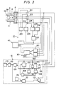
- Fig. 2 is a diagram showing an example of the grip device of the present invention and a control circuit thereof;
- Figs. 3 and 4 are characteristic diagrams for explaining the principle of detecting a grasping force in the present invention;
- Fig. 5 is an explanatory view showing a workpiece presence detecting operation according to the grip device of the present invention;
- Fig. 6 is a characteristic diagram corresponding to Fig. 5;
- Fig. 7 is a plan view showing another example 'of the grip device of the present invention;
- Fig. 8 is a view showing another example of a bimorph type piezoelectric element which constitutes the grip device of the present invention;
- Fig. 9 is a front view, partly in section, showing still another example of the grip device of the present invention;
- Fig. 10 is a view showing grasping claws which constitute another example of the device of the present invention shown in Fig. 9, and an example of a drive circuit thereof;
- Fig. 11 is a view showing a grasp stabilizing claw which constitutes the device of the present invention shown in Fig. 9, and an °example of a drive circuit thereof; and
- Fig. 12 is a diagram for explaining the situation of voltages which are applied to respective bimorph type piezoelectric elements to serve as the driving sources of corresponding claws in the device of the present invention shown in Fig. 9.
- Now, embodiments of the present invention will be described with reference to the drawings.
- Fig. 1 shows an example of a robot which is furnished with an example of a grip device according to the present invention. In this figure,
numeral 1 designates a base, numeral 2 a swivel body which is turnably mounted on thebase 1, numeral 3 a first arm which is rotatably mounted on theswivel body 2, numeral 4 a second arm which is rotatably mounted on thefirst arm 3,numeral 5 an auxiliary arm, numeral 6 a wrist which is mounted on the front end of the second arm 4, andnumeral 7 the grip device which is installed on thewrist 6. Thisgrip device 7 is composed of agrip body 8 which is attached to theaforementioned wrist 6, andfingers 9 which are formed by a pair of bimorph type piezoelectric elements mounted on thegrip body 8. - Next, a circuit arrangement for the actuator control and sensor function of the
fingers 9 formed by the pair of bimorph type piezoelectric elements will be described with reference to Fig. 2. Each of the pair offingers 9 is constructed of twopiezoelectric elements fingers 9 are avoltage feed circuit 10 for effectuating the actuator function, a workpiece presencediscriminating circuit 20 for effectuating the sensor function, and a workpiecetouch detecting circuit 30. Numeral 40 in Fig. 2 designates a control circuit for the robot. - The arrangements of the above
voltage feed circuit 10, workpiece presencediscriminating circuit 20 and workpiecetouch detecting circuit 30 will be explained in succession. - The
voltage feed circuit 10 deforms thefingers 9 constructed of the bimorph type piezoelectric elements in the directions of grasping a workpiece, and controls the grasping force thereof to a set value.Numeral 101 indicates a power source unit which applies a D.C. voltage to the bimorph typepiezoelectric elements fingers 9, and the output voltage of which can be adjusted.Numeral 102 indicates a variable frequency oscillator which is connected to the bimorph typepiezoelectric elements finger 9. A frequency signal from thisvariable frequency oscillator 102 is applied to the bimorph typepiezoelectric elements finger 9. These bimorph typepiezoelectric elements resistor 103. Further, they are bridge-connected to acapacitor 104 and aresistor 105, the capacitor having a capacitance which is substantially equal to the capacitance of thepiezoelectric elements resistor 103 and theresistor 105 are set at equal impedances.Rectifier circuits resistors recitifer circuits differential amplifier 108. Thisdifferential amplifier 108 evaluates the difference between the output voltages from therectifier circuits variable frequency oscillator 102 so as to make the difference zero. Connected to the terminals of thevariable frequency oscillator 102 is afrequency detector 109 which detects a frequency variation. The frequency variation detected by thefrequency detector 109 is delivered to afunction generator 110 and acomparator 111. Thefunction generator 110 provides an acting external force W on the basis of the detected frequency variation Af. The relationship between the frequency variation Af and the external force W will be described later. The external force W from thefunction generator 110 is displayed on adisplay unit 112. On the other hand, thecomparator 111 controls the output voltage of thepower source unit 101 on the basis of the voltage of the frequency variation from thefrequency detector 109 and a reference voltage corresponding to a set grasping force from a referencevoltage setting unit 113, thereby to control the grasping force of thefingers 9 to the set value. - Next, the relationship between the frequency variation Af and the external force W described above, in other words, the principle of force detection will be explained with reference to Fig. 3.
- Fig. 3 shows the frequency characteristics of the bimorph type piezoelectric element for use in the present invention. In the figure, the axis of abscissas represents the frequency F, and the axis of ordinates the impedance Z of the piezoelectric element. A curve X in the figure shows the characteristic which is exhibited when no external force acts on the piezoelectric element, and a curve Y the characteristic which is exhibited when an external force acts on the piezoelectric element. Further, a straight line X' shows the frequency characteristic of a capacitor having the same capacitance as that of the piezoelectric element. Letting w denote the angular frequency and C denote the capacitance of the capacitor, the frequency characteristic is expressed by 1/wC. Accordingly, when the equivalent capacitance of the piezoelectric element is known beforehand and the capacitance C of the capacitor is selected to this value, the impedances Z agree at a point Ax. The impedance Z at this time is let be ZAX, and the frequency F is let be f". When the external force W is exerted on the piezoelectric element under the state of the frequency fA, the impedance Z changes in accordance with the curve Y, to a value ZAY corresponding to a point Ay on this curve Y. That is, the impedance Z changes from ZAX to ZAY. Therefore, in a case where the frequency of the voltage to be applied to the piezoelectric element is changed so as to equalize the impedance Z of the piezoelectric element to the impedance Z set with the equivalent capacitance C, both the impedances Z agree at a point By when this frequency has become fe. The external force W acting on the piezoelectric element, namely, the grasping force can be known by knowing the frequency change Af at this time. The relationship between the frequency change Af and the external force W has a very good linearity as shown in Fig. 4. This relationship is set in the foregoing
function generator 110. According to the principle stated above, thevoltage feed circuit 10 controls the grip of the pair offingers 9 and has the functon of detecting the grasping force. - Next, the work
presence discriminating circuit 20 mentioned before will be described with reference to Fig. 2. - The workpiece
presence discriminating circuit 20 disciminates the presence or absence of a workpiece with no contact, using one of the pairedfingers 9 moved to workpiece grasping positions as an oscillating side and the other as a receiving side likewise to an ultrasonic wave sensor. To this end, afrequency oscillator 203 is connected to onefinger 9 throughswitches voltage detector 206 is connected to theother finger 9 throughswitches voltage detector 206 detects a generated voltage based on the vibrations of theother finger 9 which are induced by the vibrations of onefinger 9, and the detected voltage value is delivered to adiscrimination circuit 207. Thediscrimination circuit 207 evaluates the difference AV between the voltage value VA from thevoltage detector 206 and the induced voltage Vo of the piezoelectric element for the absence of the workpiece, set in areference voltage generator 208. Thus, it judges the presence of the workpiece between thefingers 9 when a value (AVNO) obtained by dividing the difference voltage AV by the induced voltage Vo is greater than a set value, and it judges the absence of the workpiece between thefingers 9 when the value is less than the set value. Upon judging the absence of the workpiece between thefingers 9, thediscrimination circuit 207 controls aswitch changer 209 to an open position and delivers, for example, a grip operation stopping command to therobot control circuit 40. - The principle of discriminataing the presence or absence of the workpiece stated above will be elucidated with reference to Figs. 5 and 6.
- Now, when the workpiece A is situated between the
fingers 9 as shown in Fig. 5 and it is moved from the base parts of thefingers 9 toward the distal ends thereof, the relationship between the moved distance L of the workpiece A along thefingers 9 and the voltage ratio AVNO becomes a characteristic illustrated in Fig. 6. In the figure, the ΔV/V0 value corresponding to a position L, at which thefingers 9 can reliably grasp the workpiece A becomes A1, so that the value A, is set as the reference voltage set value of thediscrimination circuit 207. Thus, when the value ΔV/V0 is greater than the set value, the presence of the workpiece A between thefingers 9 can be discriminated, and when it is less than, the absence of the workpiece A between thefingers 9 can be discriminated in non-contacting fashion. - Next, the workpiece
touch detecting circuit 30 mentioned before will be described with reference to Fig. 2. - The workpiece
touch detecting circuit 30 senses that thefingers 9 have touched the workpiece.Pulse detectors fingers 9 to detect pulsative voltage changes which arise when thefingers 9 have touched the workpiece. Thesepulse detectors direction discriminating circuit 303 which discriminates the moving direction of the arm of the robot. In accordance with a detection signal from thepulse detector 301 or thepulse detector 302, thedirection discriminating circuit 303 supplies therobot control circuit 40 with a signal of the moving direction of the robot arm relative to the workpiece in order to accurately position thefinger 9 to the workpiece. Thus, therobot control circuit 40 operates to control the arm of the robot so as to accurately position thefinger 9 to the workpiece. - Next, the operation of the foregoing grip device of the present invention will be described.
- First, the arms of the robot are controlled by the
control circuit 40 of the robot until thefingers 9 constructed of the piezoelectric elements are positioned to a position corresponding to the workpiece. In the workpiecepresence discriminating circuit 20 shown in Fig. 2, the switches 201-205 are changed by theswitch changer 209, and the frequency from thefrequency oscillator 203 is applied to onefinger 9 to vibrate thisfinger 9. The vibrations of thisfinger 9 propagate in the air, and vibrate theother finger 9. Thus, a voltage is generated across the terminals of theother finger 9 by the vibrations. The voltage is detected by thevoltage detector 206, and is input to thediscrimination circuit 207,On the basis of the characteristic shown in Fig. 6, in a case where the ΔV/V0 value is greater than set value A" thediscrimination circuit 207 discriminates the existence of the workpiece A between thefingers 9. In a case where it is less than A1, thecircuit 207 discriminates the nonexistance of the workpiece A between thefingers 9 and supplies therobot control circuit 40 with a robot operation stopping command or a grip operation stopping command. - Upon discriminating that the workpiece A exists between the
fingers 9, thediscrimination circuit 20 controls thechanger 209 to change the switches 201-205 to their original positions. - Subsequently, a voltage is applied to one
finger 9 by thevoltage feed circuit 10, to bend and deform thefingers 9 inwards relative to each other and to start a grasping operation. At this time, thefingers 9 undergo bending deformations with minute vibrations based on the frequency from thevariable frequency oscillator 102. - When, owing tothe bending deformations of the
fingers 9, onefinger 9 has touched the workpiece A in advance of the otherfinger9, a pulsative voltage change arises across the terminals of onefinger 9. The pulsative voltage change is detected by thepulse detector touch detecting circuit 30. In accordance with the detection signal, thedirection discriminating circuit 303 supplies therobot control circuit 40 with inforam- tion on the relative positional relationship between the pair offingers 9 and the workpieceA. Thus, therobot control circuit 40 controls thefingers 9 on the basis of known information such as the widthwise dimension between the pair offingers 9, so that the workpiece A is positioned betweenths fingers 9, while thefingers 9 can reliably grasp the workpiece A owing to thegrap control circuit 10. - As stated above, according to the embodiment of the present invention, even in a case where the workpiece deviates from a predetermined position of where the grip portion deviates relative to the workpiece, the workpiece can be exactly positioned and grasped. More in detail, the fingers constructed of the piezoelectric elements are not furnished with any sensors, and the operation circuits and the sensor function circuits are switched in sequence, whereby for example, the grasping operation being the actuator function and a single operation selected from or a composite operation combining the detection of a grasping force, the non-contacting detection of the presence or absence of the workpiece and the adjustment of the relative position between the fingers and the workpiece, being the sensor functions, become possible, and a safe and highly reliable grasping operation can be performed. With the present invention, it has been confirmed that a grasping force of 80 gf can be attained in a case where the
fingers 9 are constructed ofpiezoelectric elements 20 mm long, 7 mm wide and 0.5 mm thick. - While the foregoing embodiment has fixed the grasping interval of the pair of
fingers 9, an arrangement is also possible wherein, as shown in Fig. 7, twofingers 9 formed by piezoelectric elements are respectively mounted onholders 51, theholders 51 are held in engagement with aguide shaft 52 and a threadedshaft 53 disposed in agrip body 8, amotor 54 is connected to the threadedshaft 53, and the interval of the pair offingers 9 can be varied by the rotation of themotor 54. With this arrangement, various workpieces can be grasped. Moreover, the piezo- electric elements forming the pair offingers 9 may well be arranged in the so-called parallel type in which they are joined with their polarization directions held identical as illustrated in Fig. 8. It is also possible to dispose a plurality of pairs offingers 9. - According to the foregoing embodiments of the present invention, a grip portion can be sensitively positioned, and the workpiece can be exactly grasped.
- Fig. 9 shows still another embodiment of the grip device of the present invention. Referring to the figure, each of bimorph type
piezoelectric elements 91 and 91' has one end thereof fixed to agrip body 90.Grip claws 92 and 92' for grasping a workpiece A are attached to the other ends of the respectivepiezeoelectric elements 91 and 91'. In addition, thegrip body 90 is provided with agrip stabilizing claw 93. Thisclaw 93 is driven by a bimorph typepiezoelectric element 95 one end of which is fixed by asupport 94. - The grip device of the present invention thus constructed is mounted on the front end of the
wrist 6 of a robot, and performs the grasping operation in cooperation with the operation of the robot proper.Numerals 96 and 96' designate covers, which are intended to protect the bimorph typepiezoelectric elements 91 and 91'. - Fig. 10 shows an example of a driver circuit for
grip claws 92 and 92' which constitute another embodiment of the grip device of the present invention shown in Fig. 9. Referring to Fig. 10, twoD.C. voltage sources piezoelectric elements 91 and 91' through switches 101. Since, owing to such an arrangement, voltages of opposite polarities can be applied to the respectivepiezoelectric elements 91 and 91', thesepiezoelectric elements 91 and 91' displace thegrip claws 92 and 92' in the direction of nipping a workpiece A or in the direction of releasing it. In a case where no voltage is externally applied to thepiezoelectric elements 91 and 91', no deformation arises. Further, the grasping operation of theaforementioned grip claws 92 and 92' will be described. In a case where no voltage is applied to the terminals of the bimorph typepiezoelectric elements 91 and 91', thegrip claws 92 and 92' are in states indicated by solid lines. In a case where voltages are applied to the terminals, the grip claws are displaced as indicated by broken lines. When the polarities of the applied voltages are opposite, also the displacements of thegrip claws 92 and 92' become opposite in direction. In case of nipping the workpiece A, accordingly, thegrip claws 92 and 92' are moved to a workpiece grasping position in the states of the broken lines in Fig. 10, and the polarities of the applied voltages are thereafter reversed, whereby the workpiece A can be grasped. - Fig. 11 shows an example of a driver circuit for a
grip stabilizing claw 93 which is used for still another embodiment of the device of the present invention shown in Fig. 9. Referring to Fig. 11, thegrip stabilizing claw 93 operates to as to depress or release a workpiece A, depending upon the polarity of a voltage which is applied to a bimorph typepiezoelectric element 95. This bimorph typepiezoelectric element 95 has a sensor function for detecting a grasping force, and controls the grasping force of the workpiece A. More specifically, a driver circuit composed of apower source circuit 130 for directly affording a deformation and aforce detection circuit 131 for detecting a pressing force is connected to the bimorph typepiezoelectric element 95. Theforce detection circuit 131 detects the pressing force acting on the bimorph typepiezoelectric element 95 and inputs the result to thepower source circuit 130 so as to adjust the output voltage of thepower source circuit 130, thereby to regulate the magnitude of deformation of the bimorph typepiezoelectric element 95. Thus, a required pressing force can be attained. - The force detection in the
force detection circuit 131 is carried out according to the same principle as illustrated in Fig. 3, and shall not be repeatedly explained. - Fig. 12 shows the movements of the
claws piezoelectric elements curve 20 indicates the voltage variation of theclaw 93, and curves 21 and 22 indicate the circumstances of the voltage variations of theclaws 91 and 91' which nip the workpiece A directly. - In a case where a robot arm 4 is operated to bring the
grip claws 92 and 92' close to the workpiece A, the polarities of voltages applied to the bimorph typepiezoelectric elements 91 and 91' which operate theclaws 92 and 92' for nipping the workpiece A are opposite to each other, in the sense that the interval between these claws is wide. Meanwhile, the bimorph typepiezoelectric element 95 for driving theclaw 93 is supplied with a voltage with which this claw is deformed to the side of the workpiece A. When the grip device has approached the workpiece A, theclaw 93 touches the workpiece A first and the voltage changes at that point of timely. From the point of time Tl, the polarities of the voltages applied to the bimorph typepiezoelectric element 91 for operating theclaw 92 and the bimorph type piezoelectric element 91' for driving the claw 92' are respectively changed into the opposite direction, while at the same time the voltage applied to the bimorph typepiezoelectric element 95 for driving theclaw 93 is changed to the opposite polarity. Under this state, the workpiece A is nipped. The gradual inversion of the polarities of the voltages applied to theclaws 92 and 92' is for the prevention of damages in the case where the workpiece A is fragile, and it can be suitably adjusted depending upon the properties of the workpiece A. - After the workpiece A has been nipped by the
claws 92 and 92', a D.C. voltage with alternating current superposed thereon is applied to the bimorph typepiezoelectric element 95 for driving theclaw 93, to reliably hold the workpiece A from a point of time T2, while at the same time the force detection is executed so as to establish a predetermined pressing force. Subsequently, the robot arm 4 performs a predetermined operation. Thereafter, the workpiece A is released. The release can be realized by applying voltages reversely to those in the case of grasping the workpiece. - Since the deformation of the bimorph type
piezoelectric elements 91 and 91' are limited, the dimensions of the workpiece A to be grasped are also subject to limitations. Therefore, the grip mechanism may well be furnished with means by which the interval of theclaws 92 and 92' for nipping the workpiece A can be changed continuously or stepwise to fixed lengths. - While, in the above embodiments, the detection of the pressing force has been applied to the control of the operation of the
claw 93, it may well be simultaneously applied to the adjustment of the workpiece grasping force owing to theclaws 92 and 92'. - According to the foregoing embodiment of the present invention, the structure of a slide portion forming a dust source is not included, so that a grip device free from dust which is suitable for use in a clean atmosphere such as clean room can be provided. Moreover, since a grasping force can be controlled by a force detecting mechanism, the reliable grip of a workpiece to possible and the damage thereof can be prevented. Besides, the grip device is simple in mechanism and is light in weight.
Claims (9)
Applications Claiming Priority (4)
| Application Number | Priority Date | Filing Date | Title |
|---|---|---|---|
| JP22773884A JPS61109683A (en) | 1984-10-31 | 1984-10-31 | gripping device |
| JP227738/84 | 1984-10-31 | ||
| JP60080112A JPH0641115B2 (en) | 1985-04-17 | 1985-04-17 | Gripping device |
| JP80112/85 | 1985-04-17 |
Publications (2)
| Publication Number | Publication Date |
|---|---|
| EP0180226A1 EP0180226A1 (en) | 1986-05-07 |
| EP0180226B1 true EP0180226B1 (en) | 1988-09-28 |
Family
ID=26421164
Family Applications (1)
| Application Number | Title | Priority Date | Filing Date |
|---|---|---|---|
| EP85113876A Expired EP0180226B1 (en) | 1984-10-31 | 1985-10-31 | Grip device |
Country Status (3)
| Country | Link |
|---|---|
| US (1) | US4667997A (en) |
| EP (1) | EP0180226B1 (en) |
| DE (1) | DE3565221D1 (en) |
Families Citing this family (34)
| Publication number | Priority date | Publication date | Assignee | Title |
|---|---|---|---|---|
| CA1276710C (en) * | 1983-11-30 | 1990-11-20 | Kazuo Asakawa | Robot force controlling system |
| US4680523A (en) * | 1986-03-13 | 1987-07-14 | Lord Corporation | Apparatus and method for handling articles in automated assembly processes |
| US4714399A (en) * | 1986-05-02 | 1987-12-22 | Cascade Corporation | Automatically-guided vehicle having load clamp |
| FR2599994B1 (en) * | 1986-06-12 | 1989-09-29 | Controle Travaux Publics Et | METHOD AND DEVICE FOR SELECTING AND HANDLING OBJECTS FROM A COLLECTION THEREOF |
| US4792715A (en) * | 1987-11-16 | 1988-12-20 | Barsky Michael F | Robot gripper control system using PVDF piezoelectric sensors |
| DE3741614A1 (en) * | 1987-12-09 | 1989-06-29 | Wolters Peter Fa | Device for holding a part |
| FR2624407B1 (en) * | 1987-12-14 | 1993-08-27 | Controle Travaux Publics Et | PLANT FOR HANDLING BOOKS OR OTHER FLAT OBJECTS DISPOSED IN STORAGE TANKS |
| US5161846A (en) * | 1988-08-23 | 1992-11-10 | Canon Kabushiki Kaisha | Hand apparatus |
| WO1990003044A1 (en) * | 1988-09-12 | 1990-03-22 | Microflex Technology, Inc. | Protected piezoelectric polymer bimorph |
| US5049775A (en) * | 1988-09-30 | 1991-09-17 | Boston University | Integrated micromechanical piezoelectric motor |
| US5034645A (en) * | 1989-01-13 | 1991-07-23 | Digital Equipment Corporation | Micro-beam tactile sensor for the measurement of vertical position displacement |
| US5046773A (en) * | 1990-01-02 | 1991-09-10 | Hewlett-Packard Company | Micro-gripper assembly |
| US5064234A (en) * | 1990-08-02 | 1991-11-12 | Motorola, Inc. | Vacuum nozzle and conductance sensor |
| DE4037883A1 (en) * | 1990-11-28 | 1992-06-04 | Hofmann Maschinenbau Gmbh | DEVICE FOR GRIPING WORKPIECES, ESPECIALLY ROTORS |
| DK0532774T3 (en) * | 1991-09-16 | 1996-03-18 | Sig Schweiz Industrieges | Grabs a manipulator |
| US5332275A (en) * | 1991-11-27 | 1994-07-26 | Microscience Group, Inc. | Microgripper |
| US5788453A (en) * | 1996-05-30 | 1998-08-04 | Applied Materials, Inc. | Piezoelectric wafer gripping system for robot blades |
| DE50214847D1 (en) * | 2001-10-31 | 2011-02-17 | Komax Holding Ag | Handling device for wire line, insertion machine and insertion method with such a handling device |
| FR2879122B1 (en) | 2004-12-15 | 2008-10-03 | Inergy Automotive Systems Res | PROCESS FOR THE MANUFACTURE OF A PLASTIC FUEL TANK HAVING IMPROVED FLOWING RESISTANCE |
| CA2551191C (en) * | 2006-06-23 | 2016-04-05 | Keekyoung Kim | Electrothermally-driven mems microgrippers with integrated dual-axis capacitive force sensors |
| US8979149B2 (en) * | 2009-02-17 | 2015-03-17 | Yu Sun | Device for grasping and active release of micro and nano objects |
| US8550519B2 (en) * | 2009-10-17 | 2013-10-08 | GM Global Technology Operations LLC | Mechanical grippers utilizing active material activation |
| DE102010052396A1 (en) * | 2010-11-24 | 2012-05-24 | Kuka Roboter Gmbh | Method and device for controlling a peripheral component of a robot system |
| JP5811785B2 (en) * | 2011-11-08 | 2015-11-11 | セイコーエプソン株式会社 | Sensor element, force detection device and robot |
| DE102013101883A1 (en) * | 2013-02-26 | 2014-08-28 | Krones Ag | Method for monitoring operation of gripping system for gripping containers e.g. plastic performs, involves evaluating mechanical vibrations of vibration measurement device during and/or after release of plastic preform |
| US8950795B2 (en) * | 2013-04-16 | 2015-02-10 | Raytheon Company | Robotic grabber and method of use |
| JP6467809B2 (en) * | 2014-08-13 | 2019-02-13 | セイコーエプソン株式会社 | Piezoelectric driving device and driving method thereof, robot and driving method thereof |
| JP6543951B2 (en) * | 2015-02-18 | 2019-07-17 | セイコーエプソン株式会社 | Piezoelectric drive device, robot, and method of driving them |
| CN108025407B (en) * | 2015-09-18 | 2021-04-13 | 索尼公司 | Attachment device, attachment method, and hand mechanism |
| CN106482921B (en) * | 2016-11-25 | 2019-01-18 | 华南理工大学 | A kind of two degrees of freedom closed chain compliant mechanism vibration measurement control device and method |
| JP7000838B2 (en) * | 2017-12-18 | 2022-01-19 | セイコーエプソン株式会社 | Grip hand and robot |
| CN108638104A (en) * | 2018-06-04 | 2018-10-12 | 宁波恒立德机器人自动化有限公司 | A kind of multifunctional combination tooling paw |
| US10933535B2 (en) * | 2018-08-22 | 2021-03-02 | Flexiv Ltd. | Robot and gripper with synthetic fibrillar adhesive |
| FR3102946B1 (en) * | 2019-11-13 | 2022-04-01 | Percipio Robotics | Device for microactuator and microactuator equipped with such a device |
Family Cites Families (10)
| Publication number | Priority date | Publication date | Assignee | Title |
|---|---|---|---|---|
| GB862174A (en) * | 1957-06-24 | 1961-03-01 | Rolls Royce | Improved device for remote control, movement, or handling of an object |
| FR1350846A (en) * | 1962-12-20 | 1964-01-31 | Alsacienne Atom | Electric cartridge grapple |
| FR2104696B1 (en) * | 1970-07-31 | 1973-12-07 | Electricite De France | |
| US3866966A (en) * | 1973-05-14 | 1975-02-18 | Ii Frank R Skinner | Multiple prehension manipulator |
| FR2451807A1 (en) * | 1979-03-22 | 1980-10-17 | Renault | SIX AXIS MANIPULATOR |
| SU863332A1 (en) * | 1979-12-21 | 1981-09-15 | Предприятие П/Я В-2438 | Manipulator gripper |
| SU867646A1 (en) * | 1980-01-07 | 1981-09-30 | Каунасский Политехнический Институт Им. Антанаса Снечкуса | Micromanipulator gripper |
| SU867647A1 (en) * | 1980-01-07 | 1981-09-30 | Каунасский Политехнический Институт Им. Антанаса Снечкуса | Micromanipulator gripper |
| DD208578A1 (en) * | 1982-07-22 | 1984-04-04 | Pumpen Und Verdichter Wissensc | GRABS FOR MANIPULATORS |
| SU1096098A1 (en) * | 1983-01-07 | 1984-06-07 | Институт Проблем Механики Ан Ссср | Manipulator grip |
-
1985
- 1985-10-28 US US06/792,284 patent/US4667997A/en not_active Expired - Fee Related
- 1985-10-31 EP EP85113876A patent/EP0180226B1/en not_active Expired
- 1985-10-31 DE DE8585113876T patent/DE3565221D1/en not_active Expired
Also Published As
| Publication number | Publication date |
|---|---|
| EP0180226A1 (en) | 1986-05-07 |
| US4667997A (en) | 1987-05-26 |
| DE3565221D1 (en) | 1988-11-03 |
Similar Documents
| Publication | Publication Date | Title |
|---|---|---|
| US4667997A (en) | Grip device | |
| US5788453A (en) | Piezoelectric wafer gripping system for robot blades | |
| JP2011224695A (en) | System for controlling holding of robot, and robot | |
| JP2019025623A (en) | Robot system and robot control device | |
| JPH04240087A (en) | Gripping method and device | |
| EP0518303A2 (en) | Rate mode hand controller with force reflection | |
| Osswald et al. | Mechanical system and control system of a dexterous robot hand | |
| JPH07186078A (en) | Robot hand controller | |
| JP2005144573A (en) | Control method for gripping force of robot hand | |
| Hill et al. | Manipulation based on sensor-directed control: an integrated end effector and touch sensing system | |
| JPH10249767A (en) | Mobile object gripping device and control method thereof | |
| JP2838582B2 (en) | Robot hand grip control method | |
| JP4888375B2 (en) | Robot hand | |
| Choi et al. | A force/moment sensor for intuitive robot teaching application | |
| JPH01210285A (en) | Robot hand having grappling force detecting function | |
| JP3187191B2 (en) | Robot finger grip force detection device | |
| JPS61109683A (en) | gripping device | |
| JPH04189484A (en) | Grasping control method of robot hand | |
| SU867647A1 (en) | Micromanipulator gripper | |
| SU1296406A1 (en) | Sensitized gripping device of robot | |
| JPH0641115B2 (en) | Gripping device | |
| JPH02190285A (en) | Hand for robot | |
| JP2689702B2 (en) | Robot hand grip control method | |
| KR101853181B1 (en) | Sliding sensor and robot hand sensing sliding | |
| EP0173234A1 (en) | Robotic grip assembly |
Legal Events
| Date | Code | Title | Description |
|---|---|---|---|
| PUAI | Public reference made under article 153(3) epc to a published international application that has entered the european phase |
Free format text: ORIGINAL CODE: 0009012 |
|
| AK | Designated contracting states |
Kind code of ref document: A1 Designated state(s): DE FR GB |
|
| 17P | Request for examination filed |
Effective date: 19860418 |
|
| 17Q | First examination report despatched |
Effective date: 19871002 |
|
| GRAA | (expected) grant |
Free format text: ORIGINAL CODE: 0009210 |
|
| AK | Designated contracting states |
Kind code of ref document: B1 Designated state(s): DE FR GB |
|
| REF | Corresponds to: |
Ref document number: 3565221 Country of ref document: DE Date of ref document: 19881103 |
|
| ET | Fr: translation filed | ||
| PLBE | No opposition filed within time limit |
Free format text: ORIGINAL CODE: 0009261 |
|
| STAA | Information on the status of an ep patent application or granted ep patent |
Free format text: STATUS: NO OPPOSITION FILED WITHIN TIME LIMIT |
|
| 26N | No opposition filed | ||
| PGFP | Annual fee paid to national office [announced via postgrant information from national office to epo] |
Ref country code: FR Payment date: 19921019 Year of fee payment: 8 |
|
| PGFP | Annual fee paid to national office [announced via postgrant information from national office to epo] |
Ref country code: GB Payment date: 19921021 Year of fee payment: 8 |
|
| PGFP | Annual fee paid to national office [announced via postgrant information from national office to epo] |
Ref country code: DE Payment date: 19921222 Year of fee payment: 8 |
|
| PG25 | Lapsed in a contracting state [announced via postgrant information from national office to epo] |
Ref country code: GB Effective date: 19931031 |
|
| GBPC | Gb: european patent ceased through non-payment of renewal fee |
Effective date: 19931031 |
|
| PG25 | Lapsed in a contracting state [announced via postgrant information from national office to epo] |
Ref country code: FR Effective date: 19940630 |
|
| PG25 | Lapsed in a contracting state [announced via postgrant information from national office to epo] |
Ref country code: DE Effective date: 19940701 |
|
| REG | Reference to a national code |
Ref country code: FR Ref legal event code: ST |