EP0180140A2 - Method for analyzing impurities in liquid and apparatus therefor - Google Patents
Method for analyzing impurities in liquid and apparatus therefor Download PDFInfo
- Publication number
- EP0180140A2 EP0180140A2 EP85113454A EP85113454A EP0180140A2 EP 0180140 A2 EP0180140 A2 EP 0180140A2 EP 85113454 A EP85113454 A EP 85113454A EP 85113454 A EP85113454 A EP 85113454A EP 0180140 A2 EP0180140 A2 EP 0180140A2
- Authority
- EP
- European Patent Office
- Prior art keywords
- impurities
- analyzing
- phase
- light
- liquid
- Prior art date
- Legal status (The legal status is an assumption and is not a legal conclusion. Google has not performed a legal analysis and makes no representation as to the accuracy of the status listed.)
- Granted
Links
Images


Classifications
-
- G—PHYSICS
- G01—MEASURING; TESTING
- G01N—INVESTIGATING OR ANALYSING MATERIALS BY DETERMINING THEIR CHEMICAL OR PHYSICAL PROPERTIES
- G01N21/00—Investigating or analysing materials by the use of optical means, i.e. using sub-millimetre waves, infrared, visible or ultraviolet light
- G01N21/17—Systems in which incident light is modified in accordance with the properties of the material investigated
- G01N21/1702—Systems in which incident light is modified in accordance with the properties of the material investigated with opto-acoustic detection, e.g. for gases or analysing solids
Definitions
- This invention relates to a method and an apparatus for analyzing impurities in liquid, and more particularly to a method and an apparatus for analyzing impurities in various kinds of liquid such as ultra-pure water adapted to classify the impurities into soluble substance, insoluble substance and impurities in the form of bubbles, and to measure their concentrations separately.
- the photoacoustic analyzing method can be applied to highly sensitive analyzing and is useful not only for analysis of true solutions but also for that of suspensions.
- no technique has been known, which is adapted to measure separately not only insoluble impurities but also soluble ones (impurities in the form of ions) in liquid, utilizing such characteristics as described above of the photoacoustic analyzing method. This is because theoretical relations between measurement conditions such as the light modulation frequency for the photoacoustic analyzing apparatus and information obtained under those conditions are not known.
- the amount of impurities contained in ultra-pure water is in the order of ppt's and this concentration level is below the lower detection limit of the conventional analyzing method such as chromatography, colorimetry, etc. Consequently, it is difficult to apply the prior art analyzing methods to analysis of impurities in ultra-pure water.
- the object of this invention is to provide a method for analyzing impurities in liquid and an apparatus therefor, which are adapted to classify impurities in liquid to be measured into soluble and insoluble impurities as well as those in the form of bubbles, and to measure their concentration separately.
- a method for analyzing impurities in liquid is carried out by measuring a photoacoustic signal obtained by irradiating onto a liquid to be measured an intensity-modulated light, obtaining the relationship between the modulation frequency of the intensity-modulated light (light modulation frequency) and the phase of the photoacoustic signal, and determining the kinds of impurities in the liquid, as classified into soluble and insoluble ones and those in the form of bubbles on the basis of the information thus obtained.
- an apparatus for analyzing impurities in liquid comprising a light source; at least one light modulator for transforming light from the light source into intensity-modulated light having a given constant frequency; at least one cell disposed at a position where it is irradiated with the intensity-modulated light and containing therein liquid to be measured; at least one phase detection device for detecting the phase of the photoacoustic signals coming from the cell; a calculating device for analyzing impurities in the liquid on the basis of information obtained by the phase detection device; and a control device for controlling the modulation frequency (light modulation frequency) of the intensity-modulated light derived from the light modulator.
- a photoacoustic signal obtained by irradiating onto a liquid sample such as ultra-pure water an intensity-modulated light is measured and the kinds of impurities in the liquid sample as classified into soluble and insoluble substances and substance in the form of bubbles and the concentrations thereof are determined on the basis of the relation between the modulation frequency (light modulation frequency) of the intensity-modulated light and the phase, as well as the intensity, of the photoacoustic signal.
- the principle of this invention is based on the fact that the relation between the light modulation frequency and the phase of the photoacoustic signals varies depending on the property of impurities, as indicated in Table 1.
- an impurity particle 41 absorbs light 42 and releases heat produced by a radiationless transition in the form of a thermal flux 43 in the medium.
- This thermal flux by J J is given by the following equation, which is produced according to a temperature field T(p, t) formed around the impurity particle;
- Eqs. (14) and (15) may be represented in a polar coordinate system, as follows;
- ⁇ Q represents the phase delay due to propagation of the photoacoustic signals and ⁇ D indicates the phase delay of the photoacoustic signal due to the time interval required for release of heat produced in the impurity particles.
- the photoacoustic signal is an acoustic wave having linear characteristics, the principle of superposition is applied to the signal. Under these conditions, the intensity of the photoacoustic signal corresponds to the sum of the concentration of soluble impurities and that of insoluble ones and the resultant phase is ⁇ Q . Therefore, when the phase 8 of the lock-in amplifier for the photoacoustic signal is set at the intensity of the phase-detected photoacoustic signal represents the total amount of impurities contained in the solution. On the other hand, when ⁇ 0 satisfies and ⁇ D is distinguishable from ⁇ Q , it can be understood that the insoluble impurities can be measured separately from soluble ones.
- the projected light is refracted by bubbles, changes its path and can enter directly the detector.
- the incident light produces photoacoustic signals of the detector itself.
- the phase of the photoacoustic signal is zero. Consequently, it is possible to measure bubbles, distinguishing them from soluble and insoluble impurities.
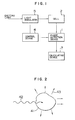
- Fig. 1 is a block diagram showing the basic structure of this invention.
- Light emitted by a light source enters a light modulator 5, in which the incident light is transformed into intensity-modulated light, whose intensity varies with a constant frequency, and a cell 2 containing a liquid sample to be measured is irradiated with this intensity-modulated light.
- the reference numeral 1 represents a phase detection device having functions to receive photoacoustic signals obtained at the cell 2 and measure the phase and the intensity of the photoacoustic signal or to take out only the photoacoustic signal which has a given phase from the received signal and measure its intensity.
- the reference numeral 4 indicates a control device, which sets the light modulation frequency in the light modulator 5 and also the phase in the phase detection device 1.
- the reference numeral 7 represents a calculating device, which classifies impurities contained in the liquid sample, calculates their amount (concentration), and displays results, if necessary, on the basis of information obtained by the phase detection device 1.
- Fig. 3 shows the first embodiment of an apparatus for analyzing impurities in liquid, in which the light modulation frequency can be set at any desired value and a lock-in amplifier is used as the phase detection device 1 for detecting the phase of the photoacoustic signals, the phase and the sensitivity of the lock-in amplifier 1 also being settable at any desired values.
- the light modulation frequency as well as the phase and the sensitivity of the lock-in amplifier are controlled by the control device coupled with a calculator on the basis of Table 1.
- a sample such as ultra-pure water, etc. is prepared and filled in a sealed type cell 2 and the photoacoustic signal derived from the sample is measured.
- an Ar laser device is used as the light source 3 and a light beam of 2.6 W having an oscillation line of 488 nm is utilized as exciting light.
- the light modulation frequency is set at 80 Hz for low frequency modulation and at 410 kHz for high frequency modulation. These light modulation frequencies sufficiently satisfy Eqs. (23) and (24), respectively, for particles of silicon dioxide having a radius of 1 ⁇ m in water.
- the phase of the lock-in amplifier 1 is set automatically at a value as mentioned before by the controller (control device) 4 and measures only the intensity of the photoacoustic signal. In this way, the total amount of impurities (concentration) in the sample can be obtained.
- the lower detection limit of the light-absorption coefficient is about 10 -8 /cm.
- the impurities are silicon dioxide particles, they can be measured down to about 20 ppt.
- the light modulation frequency is set automatically at the high frequency side and the lock-in amplifier acts as a phase detector. In this case, for a particle radius of 1 ⁇ m the phase is 45 degrees and the smallest measurable value of the phase detector of 0.5 degree corresponds to a particle radius of about 0.1 ⁇ m.
- the reference numeral 5 is the photoacoustic modulator transforming light coming from the Ar laser 3 into modulated light; 6 is the oscillator feeding the lock-in amplifier 1 and the photoacoustic modulator 5 with signals; and 7 represents the calculator (calculating device). Further, since a photoacoustic modulator 5 is used as the light modulator 5, an oscillator 6 is disposed, which drives the modulator.
- Fig. 4 the second embodiment of the apparatus according to this invention will be explained, referring to Fig. 4.
- flow type cells are used and 2 sets of light modulators M 1 , M 2' cells 2a, 2b combining the same sample and lock-in amplifiers la, lb are disposed. These 2 sets are adjusted for different measurement conditions.
- the light source 3 is an Ar laser device having an output 20 W.
- the light modulator M 1 is set at 80 Hz and M 2 at 410 kHz.
- the setting value of these light modulation frequencies can be varied by the control device 4.
- the lock-in amplifier la measures the intensity S 1 and lb measures variations in phase ⁇ D and the intensity S 2 .
- the measured values S 1 , S 2 and ⁇ D are processed by a calculator 7.
- the reference numeral 8 indicates a light distributing device disposed between the light source 3 and the light modulators M 1 , M 2' that is, 8a is a beam splitter, which directs the incident light beam toward 2 directions, and 8b is a mirror, which reflects the incident beam.
- the liquid sample 35 flows successively through the-cells 2a and 2b by means of a pump 36.
- Fig. 5 shows an example of measurements according to this embodiment. The figure shows that soluble impurities of 20 ppb flows in the region A and impurities of 60 ppt having a particle radius of 0.3 ⁇ m are detected in the region B. In the region C impurities of 30 ppt in the form of particles having a particle radius of 0.15 ⁇ m are detected. In the region D no impurities are detected.
- the relationship between the intensity of signals and the concentration in this apparatus is as follows;
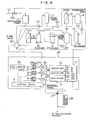
- Fig. 6 shows the third embodiment of this invention, in which the method according to this invention is applied to an ultra-pure water production apparatus.
- the reference numeral 10 indicates a raw water supply line for feeding a distillation tower 11 with raw water such as city water; 12 is an activated charcoal filter tower for eliminating organic impurities; 13 is an inverse osmotic membrane module for eliminating particles, electrolyte, etc.; 14 is an intermediate tank; 15 is an ion exchange resine tower for eliminating electrolyte, etc.; 16 is a pure water tank for storing produced pure water (specific resistance greater than 1 - 10 M ⁇ cm); 17 is an ultra-violet ray sterilizer for sterilizing bacteria; 18 is a polisher for eliminating electrolyte; and 19 is an ultra-filtration membrane module for eliminating fine particles.
- This ultra-filtration membrane module 19 feeds a 5-way valve 20 with ultra-pure water, whose specific resistance is greater than 17-18 M ⁇ cm and in which the number of fine particles larger than 0.1-0.2 ⁇ m is smaller than 50/cc and that of living bacteria is smaller than 0.1/cc.
- 21 to 24 represent water sending pumps or pressuring pumps.
- Produced ultra-pure water is supplied successively from the 5-way valve 20 to the cells 2a, 2b and 2c of the apparatus 25 for analyzing impurities.
- 3a indicates a light source utilizing a high energy C0 2 laser; 9a is a beam splitter; 9c is a half mirror; 9b is a mirror; M 1 , M 2 and M 3 are light modulators; la, lb and lc are lock-in amplifiers; 4 is a controlling device controlling the light modulators M 1 to M 3 and the lock-in amplifiers la to lc; and 7 is a calculating device for classifying impurities into various sorts and calculating their concentration on the basis of information coming from the lock-in amplifiers la to lb.
- This calculating device 7 is provided also with the function to control a valve 10a mounted on the raw water supply line 10, the 5-way valve 20 and another valve 27, depending on analysis results of the produced ultra-pure water.
- the light modulation frequency w l of the light modulator M 1 is set at 33 Hz and the light frequencies w 2 and w 3 of the light modulators M 2 and M 3 , respectively, are set at 4 MHz.
- the total amount of impurities and the amount of soluble impurities are measured on the basis of the intensity of the photoacoustic signals S 1 and S 2 , respectively.
- the lock-in amplifier lc measures the phase ⁇ and the intensity S 3 of the photoacoustic signals.
- the mean radius of particles of insoluble impurities is obtained from the phase ⁇ and the concentration of the insoluble impurities is calculated on the basis of the intensity S 3 .
- the signals coming from the lock-in amplifiers la-lc are directly inputted to the calculating device 26 and control the 5-way valve 20 described above as follows.
- the analyzing apparatus 25 can be also so constructed that only a part of the produced ultra-pure water is bypassed therethrough.
- Fig. 7 shows the fourth embodiment of this invention, in which an apparatus for analyzing impurities according to this invention is applied to industrial waste water.
- the reference numerals, which are used also in Fig. 4 or Fig. 6, represent identical or corresponding parts.
- the reference numeral 29 indicates a waste water ejecting line; 30 is a waste water treatment installation; 31 is a storing reservoir; and 32 is a sampling device. Samples taken in this sampling device 32 are supplied successively to the cells 2a, 2b and 2c of the apparatus for analyzing impurities.
- an Ar laser device of 5 W is used as the light source 3.
- the other conditions are identical to those described for the embodiment illustrated in Fig. 6.
- the photoacoustic signals (PA signals) coming from the cells 2a to 2c are inputted to the lock-in amplifiers la to lc, respectively, and the intensities S l to S 3 of the photoacoustic signals from the lock-in amplifiers la to lc as well as the phase O D of the photoacoustic signals from the lock-in amplifier lc are inputted to the display-recording device (calculating device) 7.
- the samples, which have passed through the cells 2a to 2c, are ejected by the drain.
- Fig. 8 shows a result obtained by analyzing industrial waste water by means of the apparatus indicated in Fig. 7.
- the apparatus for analyzing impurities according to this invention can be applied to the case where samples to be analyzed are turbid and suspended.
- impurities in liquid are analyzed on the basis of information on the modulation frequency of intensity-modulated light, with which liquid samples are irradiated, the relationship between the phase of the intensity-modulated light and that of the photoacoustic signal, and the intensity of the photoacoustic signal, it is possible to classify impurities in liquid into soluble and insoluble ones and those in the form of bubbles and also to measure their concentration separately.
Landscapes
- Physics & Mathematics (AREA)
- Health & Medical Sciences (AREA)
- Life Sciences & Earth Sciences (AREA)
- Chemical & Material Sciences (AREA)
- Analytical Chemistry (AREA)
- Biochemistry (AREA)
- General Health & Medical Sciences (AREA)
- General Physics & Mathematics (AREA)
- Immunology (AREA)
- Pathology (AREA)
- Investigating Or Analysing Materials By Optical Means (AREA)
- Investigating Or Analyzing Materials By The Use Of Ultrasonic Waves (AREA)
Abstract
Description
- This invention relates to a method and an apparatus for analyzing impurities in liquid, and more particularly to a method and an apparatus for analyzing impurities in various kinds of liquid such as ultra-pure water adapted to classify the impurities into soluble substance, insoluble substance and impurities in the form of bubbles, and to measure their concentrations separately.
- It is known that the photoacoustic spectroscopy is useful for a highly sensitive spectroscopic analyzing method, when it is applied to liquid samples and used as a colorimetric analyzing apparatus. Shohei Oda, Tsuguo Sawada and Hitoshi Kamada have reported in an article entitled "Determination of Ultra Trace Cadmium by Laser-Induced Photoacoustic Absorption Spectrometry", Analytical Chemistry, Vol. 52, p. 650 (1980), that cadmium can be analyzed down to 12 ppt in the form of a complex salt with dithizone by means of a photoacoustic analyzing apparatus. Further, Shohei Oda, Tsuguo Sawada, Toyohiko Moriguchi and Hitoshi Kamada have reported that when the photoacoustic analyzing method is applied to suspension of barium sulfate its detection limit is 30 ppb in an article entitled "Analysis of Turbid Solution by Laser-Induced Photoacoustic Spectroscopy", Analytical Chemistry, Vol. 52, p. 650 (1980). It has been shown in this example that the calibration curve of the suspension doesn't depend on the diameter of particles, when light modulation frequency is set at 33 Hz. That is, it has been clarified that the photoacoustic analyzing method has a characteristic that it is not influenced by the diameter of suspended particles.
- However, on the other hand, it has been varified by Kitamori, et al. that the phase of photoacoustic signal depends on the diameter of suspended particles and that the diameter and the concentration of suspended particles can be measured by the photoacoustic analyzing method.
- In this way, it has been verified that the photoacoustic analyzing method can be applied to highly sensitive analyzing and is useful not only for analysis of true solutions but also for that of suspensions. However, no technique has been known, which is adapted to measure separately not only insoluble impurities but also soluble ones (impurities in the form of ions) in liquid, utilizing such characteristics as described above of the photoacoustic analyzing method. This is because theoretical relations between measurement conditions such as the light modulation frequency for the photoacoustic analyzing apparatus and information obtained under those conditions are not known.
- Furthermore, the amount of impurities contained in ultra-pure water is in the order of ppt's and this concentration level is below the lower detection limit of the conventional analyzing method such as chromatography, colorimetry, etc. Consequently, it is difficult to apply the prior art analyzing methods to analysis of impurities in ultra-pure water.
- As stated above, none of the conventional impurity analyzing methods is adapted to analyze any kind of impurities such as fine particles whose concentration is very low (insoluble substance), substance in the form of ions (soluble substance), and further impurities in the form of bubbles. Furthermore there exists no apparatus for analyzing impurities in liquid permitting not only these analyses but also on-line measurements.
- The object of this invention is to provide a method for analyzing impurities in liquid and an apparatus therefor, which are adapted to classify impurities in liquid to be measured into soluble and insoluble impurities as well as those in the form of bubbles, and to measure their concentration separately.
- In one aspect of this invention, a method for analyzing impurities in liquid is carried out by measuring a photoacoustic signal obtained by irradiating onto a liquid to be measured an intensity-modulated light, obtaining the relationship between the modulation frequency of the intensity-modulated light (light modulation frequency) and the phase of the photoacoustic signal, and determining the kinds of impurities in the liquid, as classified into soluble and insoluble ones and those in the form of bubbles on the basis of the information thus obtained.
- In another aspect of this invention, there is provided an apparatus for analyzing impurities in liquid comprising a light source; at least one light modulator for transforming light from the light source into intensity-modulated light having a given constant frequency; at least one cell disposed at a position where it is irradiated with the intensity-modulated light and containing therein liquid to be measured; at least one phase detection device for detecting the phase of the photoacoustic signals coming from the cell; a calculating device for analyzing impurities in the liquid on the basis of information obtained by the phase detection device; and a control device for controlling the modulation frequency (light modulation frequency) of the intensity-modulated light derived from the light modulator.
- According to this invention, a photoacoustic signal obtained by irradiating onto a liquid sample such as ultra-pure water an intensity-modulated light is measured and the kinds of impurities in the liquid sample as classified into soluble and insoluble substances and substance in the form of bubbles and the concentrations thereof are determined on the basis of the relation between the modulation frequency (light modulation frequency) of the intensity-modulated light and the phase, as well as the intensity, of the photoacoustic signal.
- Next, explanation will be made of the construction of the apparatus for measuring the kinds of impurities in liquid as classified into soluble and insoluble ones and those in the form of bubbles and the concentrations thereof on the basis of the relationship between the phase and the intensity of the photoacoustic signal and the light modulation frequency or the relationship between the phase set by the phase detection device for the photoacoustic signal and the light modulation frequency referring to Fig. 1 and Table 1.

- Explanation of notation
- ρs : specific weight of particles
- Cps : specific heat of particles
- h : heat transfer coefficient from particles to medium
- dc : lower detection limit of radius of particles
- φQ : phase delay due to propagation of photoacoustic signals
- φD : phase delay due to delay in time necessary for heat evacuation after incidence of light to particles
- S : intensity of photoacoustic signals
- The principle of this invention is based on the fact that the relation between the light modulation frequency and the phase of the photoacoustic signals varies depending on the property of impurities, as indicated in Table 1.
- Hereinbelow, the principle on the basis of which the relation between the measurement conditions .and information, as indicated in Table 1, can be obtained will be explained, according to the theory of the inventors of this invention on generation, propagation and detection of photoacoustic signals. Impurities absorbing periodically intensity-modulated light produce periodically heat by nonradiative processes. This heat induces periodical thermal expansion of the medium and as the result generates acoustic waves. The generated acoustic waves, i.e. photoacoustic signals are represented by P (r, t), where r represents a vector in an arbitrarily set spatial coordinate system and t represents time. The photoacoustic signals can be described as acoustic waves by the following wave equation;

- where C is the sound velocity, a is the thermal expansion coefficient of the medium, Cp is the specific heat of the medium, H (r, t) represents the time and spatial distribution of heat generated by the nonradiative processes, and ∇r is a differential operator with respect to the vector r. The solution of this wave is in general given by the following equation;

- where F is a Fourier transformation operator; H( r', w), etc. are Fourier images of a function H(ir, t); and G(r|r') is a Green function determined by the boundary conditions given by the structure, materials, etc. of the cell. The concrete representation of the photoacoustic signals P(r, t) is given by the structure and the materials of the cell as well as the concrete representation of the function H(r, t).
- In the case where the impurities are soluble, since the solution is a true solution, the spatial distribution of H(r, t) coincides with the spatial distribution of the projected light. Further, in the case where the nonradiative relaxation time of the impurities is sufficiently short and negligeable with respect to the period of the light modulation, the time distribution of H(tr, t) coincides with the time distribution of the projected light. Consequently, the following equation can be obtained;

- where a is an absorption coefficient of the solution; I0 is the intensity of the projected light; R(r) represents the spatial distribution of the projected light; and M(t) represents the time distribution of the projected light and is called the modulation function. Using Eqs. (2) and (3), P1(r, t) representing the photoacoustic signals for soluble impurities is given by a representation (4) as follows;

- Next, in the case where the impurities are insoluble, a representation for the photoacoustic signals can be deduced as follows. As indicated in Fig. 2, an
impurity particle 41 absorbslight 42 and releases heat produced by a radiationless transition in the form of a thermal flux 43 in the medium. Representing this thermal flux by J, J is given by the following equation, which is produced according to a temperature field T(p, t) formed around the impurity particle;
- where p indicates a vector representing the position of the impurity particle in the coordinate system; X is the heat conduction coefficient of the medium; and n indicates the normal vector. The temperature field T(p, t) can be obtained by using the following heat equations;


- where K is the heat diffusion coefficient; V indicates the region inside of the impurity particle; and the characters with suffix S indicate that the properties represented by the respective characters are concerned with the impurity particle. In the case where impurity particles are distributed uniformly in the cell, H(r, t) can be obtained by using the following equation;

- where N is the density in number of the impurity particles and it is related to the impurity concentration C by the following equation;

- where a indicates the density and V represents the volume of the impurity particles. ∫S in Eq. (8) indicates integration over the surfaces of the impurity particles. In the case where the impurity particles are sufficiently small and the temperature of all the impurity particles varies uniformly, by resolving Eqs. (5) to (9), H(r, w) is represented by Eq. (10) as follows;

- Substituting (r, w) of Eq. (10) for Eq. (2), the photoacoustic signals P2(r, t) coming from the impurity particles can be obtained by using the following equation;

where
- When the modulation function M(t) is a sinusoidal function having an angular frequency ω0, since


where
- When the diameter of impurity particles is nearly zero, Eq. (15) coincides with Eq. (14) and the photoacoustic signals from a liquid containing insoluble impurities become identical to those from a true solution. In order to make the intensity and the phase of the photoacoustic signals more distinctive, Eqs. (14) and (15) may be represented in a polar coordinate system, as follows;


where


- Consequently, φQ represents the phase delay due to propagation of the photoacoustic signals and φD indicates the phase delay of the photoacoustic signal due to the time interval required for release of heat produced in the impurity particles.
- By using Eqs. (12) to (22), the conditions for the classification of the impurities and the measurement of their concentrations, as indicated in Table 1, can be obtained. At first, in the case where the light modulation angular frequency w0 sufficiently satisfies

and the following equation is valid;
it can be seen from Eq. (18) that the intensity of the photoacoustic signal is independent of the size of the impurity particles. Furthermore, in this case, from Eq. (22)
can be obtained. Thus, only φQ gives the phase delay of the photoacoustic signal in Eqs. (17) and (18) so that the phase of the photoacoustic signal from the liquid containing insoluble impurities coincides with that from a solution containing soluble impurities. Since the photoacoustic signal is an acoustic wave having linear characteristics, the principle of superposition is applied to the signal. Under these conditions, the intensity of the photoacoustic signal corresponds to the sum of the concentration of soluble impurities and that of insoluble ones and the resultant phase is φQ. Therefore, when thephase 8 of the lock-in amplifier for the photoacoustic signal is set at
the intensity of the phase-detected photoacoustic signal represents the total amount of impurities contained in the solution. On the other hand, when ω0 satisfies
and φD is distinguishable from φQ, it can be understood that the insoluble impurities can be measured separately from soluble ones. In this case, the size of the impurity particles can be known from Eq. (22) and thus, in the case where the impurities particles can be assumed to be spherical, since S = 4πd2 and

- In addition, for the conditions given by Eqs. (23) and (24) the following relationship is valid;

- This means that, in the case where φD = 0, even if the projected light is modulated with a light modulation frequency satisfying Eq. (24), the impurities are not particles but all of them are soluble.
- In the case where the impurities are in the form of bubbles, the projected light is refracted by bubbles, changes its path and can enter directly the detector. In this case, the incident light produces photoacoustic signals of the detector itself. However, since the light velocity is much greater than the sound velocity, the phase of the photoacoustic signal is zero. Consequently, it is possible to measure bubbles, distinguishing them from soluble and insoluble impurities.
-
- Fig. 1 is a block diagram showing the basic structure of this invention;
- Fig. 2 is a schematic diagram for explaining the process of absorbing light and releasing heat;
- Fig. 3 is a block diagram showing the first embodiment of this invention;
- Fig. 4 is a system diagram showing the second embodiment of this invention;
- Fig. 5 shows graphs indicating measurement examples obtained by using the apparatus indicated in Fig. 4;
- Fig. 6 is a system diagram showing the third embodiment of this invention;
- Fig. 7 is a system diagram showing the fourth embodiment of this invention; and
- Fig. 8 shows graphs indicating measurement examples obtained by using the apparatus indicated in Fig. 7.
- Hereinbelow the embodiments of this invention will be explained, referring to the drawing.
- Fig. 1 is a block diagram showing the basic structure of this invention. Light emitted by a light source enters a
light modulator 5, in which the incident light is transformed into intensity-modulated light, whose intensity varies with a constant frequency, and acell 2 containing a liquid sample to be measured is irradiated with this intensity-modulated light. Thereference numeral 1 represents a phase detection device having functions to receive photoacoustic signals obtained at thecell 2 and measure the phase and the intensity of the photoacoustic signal or to take out only the photoacoustic signal which has a given phase from the received signal and measure its intensity. Thereference numeral 4 indicates a control device, which sets the light modulation frequency in thelight modulator 5 and also the phase in thephase detection device 1. Thereference numeral 7 represents a calculating device, which classifies impurities contained in the liquid sample, calculates their amount (concentration), and displays results, if necessary, on the basis of information obtained by thephase detection device 1. - Fig. 3 shows the first embodiment of an apparatus for analyzing impurities in liquid, in which the light modulation frequency can be set at any desired value and a lock-in amplifier is used as the
phase detection device 1 for detecting the phase of the photoacoustic signals, the phase and the sensitivity of the lock-inamplifier 1 also being settable at any desired values. The light modulation frequency as well as the phase and the sensitivity of the lock-in amplifier are controlled by the control device coupled with a calculator on the basis of Table 1. In this embodiment a sample such as ultra-pure water, etc. is prepared and filled in a sealedtype cell 2 and the photoacoustic signal derived from the sample is measured. In this apparatus an Ar laser device is used as thelight source 3 and a light beam of 2.6 W having an oscillation line of 488 nm is utilized as exciting light. In this apparatus, the light modulation frequency is set at 80 Hz for low frequency modulation and at 410 kHz for high frequency modulation. These light modulation frequencies sufficiently satisfy Eqs. (23) and (24), respectively, for particles of silicon dioxide having a radius of 1 µm in water. Once the low frequency modulation is selected, the phase of the lock-inamplifier 1 is set automatically at a value as mentioned before by the controller (control device) 4 and measures only the intensity of the photoacoustic signal. In this way, the total amount of impurities (concentration) in the sample can be obtained. In this case, the lower detection limit of the light-absorption coefficient is about 10-8/cm. Further, when the impurities are silicon dioxide particles, they can be measured down to about 20 ppt. When the measurement of the total amount of impurities is terminated, the light modulation frequency is set automatically at the high frequency side and the lock-in amplifier acts as a phase detector. In this case, for a particle radius of 1 µm the phase is 45 degrees and the smallest measurable value of the phase detector of 0.5 degree corresponds to a particle radius of about 0.1 µm. - In addition, in the embodiment shown in Fig. 3, the
reference numeral 5 is the photoacoustic modulator transforming light coming from theAr laser 3 into modulated light; 6 is the oscillator feeding the lock-inamplifier 1 and thephotoacoustic modulator 5 with signals; and 7 represents the calculator (calculating device). Further, since aphotoacoustic modulator 5 is used as thelight modulator 5, anoscillator 6 is disposed, which drives the modulator. - Next, the second embodiment of the apparatus according to this invention will be explained, referring to Fig. 4. In this embodiment, flow type cells are used and 2 sets of light modulators M1, M2' cells 2a, 2b combining the same sample and lock-in amplifiers la, lb are disposed. These 2 sets are adjusted for different measurement conditions. The
light source 3 is an Ar laser device having an output 20 W. The light modulator M1 is set at 80 Hz and M2 at 410 kHz. The setting value of these light modulation frequencies can be varied by thecontrol device 4. The lock-in amplifier la measures the intensity S1 and lb measures variations in phase φD and the intensity S2. The measured values S1, S2 and φD are processed by acalculator 7. Further, in the figure, thereference numeral 8 indicates a light distributing device disposed between thelight source 3 and the light modulators M1, M2' that is, 8a is a beam splitter, which directs the incident light beam toward 2 directions, and 8b is a mirror, which reflects the incident beam. Theliquid sample 35 flows successively through the-cells pump 36. Fig. 5 shows an example of measurements according to this embodiment. The figure shows that soluble impurities of 20 ppb flows in the region A and impurities of 60 ppt having a particle radius of 0.3 µm are detected in the region B. In the region C impurities of 30 ppt in the form of particles having a particle radius of 0.15 µm are detected. In the region D no impurities are detected. The relationship between the intensity of signals and the concentration in this apparatus is as follows;

- In this case, for the soluble impurities, calculations were effected, assuming that the molecular light absorption coefficient is 10 (mol. cm-2).
- Furthermore, it can be seen that at E and F bubbles are detected.
- Fig. 6 shows the third embodiment of this invention, in which the method according to this invention is applied to an ultra-pure water production apparatus.
- In the figure, the
reference numeral 10 indicates a raw water supply line for feeding a distillation tower 11 with raw water such as city water; 12 is an activated charcoal filter tower for eliminating organic impurities; 13 is an inverse osmotic membrane module for eliminating particles, electrolyte, etc.; 14 is an intermediate tank; 15 is an ion exchange resine tower for eliminating electrolyte, etc.; 16 is a pure water tank for storing produced pure water (specific resistance greater than 1 - 10 MΩcm); 17 is an ultra-violet ray sterilizer for sterilizing bacteria; 18 is a polisher for eliminating electrolyte; and 19 is an ultra-filtration membrane module for eliminating fine particles. Thisultra-filtration membrane module 19 feeds a 5-way valve 20 with ultra-pure water, whose specific resistance is greater than 17-18 MΩcm and in which the number of fine particles larger than 0.1-0.2 µm is smaller than 50/cc and that of living bacteria is smaller than 0.1/cc. Further, in the figure, 21 to 24 represent water sending pumps or pressuring pumps. - Produced ultra-pure water is supplied successively from the 5-
way valve 20 to thecells apparatus 25 for analyzing impurities. 3a indicates a light source utilizing a high energy C02 laser; 9a is a beam splitter; 9c is a half mirror; 9b is a mirror; M1, M2 and M3 are light modulators; la, lb and lc are lock-in amplifiers; 4 is a controlling device controlling the light modulators M1 to M3 and the lock-in amplifiers la to lc; and 7 is a calculating device for classifying impurities into various sorts and calculating their concentration on the basis of information coming from the lock-in amplifiers la to lb. This calculatingdevice 7 is provided also with the function to control avalve 10a mounted on the rawwater supply line 10, the 5-way valve 20 and anothervalve 27, depending on analysis results of the produced ultra-pure water. The light modulation frequency wl of the light modulator M1 is set at 33 Hz and the light frequencies w2 and w3 of the light modulators M2 and M3, respectively, are set at 4 MHz. The phase of the lock-in amplifiers la and lb is set at φD = 48° obtained previously experimentally. The total amount of impurities and the amount of soluble impurities are measured on the basis of the intensity of the photoacoustic signals S1 and S2, respectively. The lock-in amplifier lc measures the phase φ and the intensity S3 of the photoacoustic signals. Thus, the mean radius of particles of insoluble impurities is obtained from the phase φ and the concentration of the insoluble impurities is calculated on the basis of the intensity S3. The signals coming from the lock-in amplifiers la-lc are directly inputted to the calculating device 26 and control the 5-way valve 20 described above as follows. - · If S1 > 100 µV → Stop of water supply (the
valve 10a is closed.) - · If S2 > 50 µV → Redoing of purification after the inverse
osmotic membrane module 13 or the ionexchange resine tower 15. - · If S3 > 50 µV and at the same time φ > 0.5° → Redoing of purification by returning water to the upstream of the
pure water tank 16 or the ultra-filtration membrane module. - For the above described conditions it is assumed that purification is repeated, if the amount of soluble impurities is greater than about 1 ppb and if the amount of insoluble impurities is greater than 10 ppt and at the same time their particle radius is greater than 0.3 µm. Further, when the phase of the lock-in amplifier lc is 0, since bubbles are mixed in the ultra-pure water, the
valve 27 is commuted to the side of adegassing device 28 and after having degassed the ultra-pure water, it is supplied to a use point for example for semiconductor production. - Furthermore, although all the produced ultra-pure water passes through the apparatus for analyzing
impurities 25 in this embodiment, in the case where the capacity of the pure water production apparatus is large, the analyzingapparatus 25 can be also so constructed that only a part of the produced ultra-pure water is bypassed therethrough. - Fig. 7 shows the fourth embodiment of this invention, in which an apparatus for analyzing impurities according to this invention is applied to industrial waste water. In the figure, the reference numerals, which are used also in Fig. 4 or Fig. 6, represent identical or corresponding parts.
- The reference numeral 29 indicates a waste water ejecting line; 30 is a waste water treatment installation; 31 is a storing reservoir; and 32 is a sampling device. Samples taken in this sampling device 32 are supplied successively to the
cells light source 3. The other conditions are identical to those described for the embodiment illustrated in Fig. 6. The photoacoustic signals (PA signals) coming from thecells 2a to 2c are inputted to the lock-in amplifiers la to lc, respectively, and the intensities Sl to S3 of the photoacoustic signals from the lock-in amplifiers la to lc as well as the phase OD of the photoacoustic signals from the lock-in amplifier lc are inputted to the display-recording device (calculating device) 7. The samples, which have passed through thecells 2a to 2c, are ejected by the drain. - Fig. 8 shows a result obtained by analyzing industrial waste water by means of the apparatus indicated in Fig. 7.
- As indicated above, the apparatus for analyzing impurities according to this invention can be applied to the case where samples to be analyzed are turbid and suspended.
- According to the embodiments described above of this invention the following effects can be obtained.
- 1) It is possible to classify impurities into soluble and insoluble ones as well as bubbles in liquid and to measure their concentration separately.
- 2) It is possible to analyze an extremely small amount of impurities (order of ppt), because the photoacoustic spectroscopic method is applied to the detection.
- 3) It is possible to analyze also turbid samples, because the photoacoustic spectroscopic method is utilized for the detector.
- 4) It is possible to monitor impurities in liquid, because on-line measurement can be effected. Consequently, when this method is applied to the water quality control of ultra-pure water, on-line control of the water quality can be effected and production yield in semiconductor process and genetic engineering plant is increased.
- As explained above, according to this invention, since impurities in liquid are analyzed on the basis of information on the modulation frequency of intensity-modulated light, with which liquid samples are irradiated, the relationship between the phase of the intensity-modulated light and that of the photoacoustic signal, and the intensity of the photoacoustic signal, it is possible to classify impurities in liquid into soluble and insoluble ones and those in the form of bubbles and also to measure their concentration separately.
Claims (29)

where pS is the specific weight of particles to be measured; Cp is the specific heat of the particles; dc is the lower detection limit of the radius of the particles; and h represents the heat transfer coefficient from the particles to the medium; the phase e of the phase detection device (1, la, lb, lc) for detecting the phase of the photoacoustic signals being set so that it

where Q indicates the phase delay due to the propagation of the photoacoustic signals; and the total amount of impurities in liquid is calculated on the basis of the intensity of the photoacoustic signals thus phase-detected.

where pS in the specific weight of particles to be measured; Cps is the specific heat of the particles; dc is the lower detection limit of the radius of the particles; and h represents the heat rransfer coefficient from the particles to the medium; and the impurities are detected, while classifying them into soluble and insoluble ones and those in the form of bubbles on the basis of the phase of the photoacoustic signals thus obtained.
it is judged that bubbles are mixed therein; when
where φQ indicates the phase delay due to the propagation of the photoacoustic signals, it is judged that soluble impurities are mixed therein; and further when

where φD is the phase delay due to the time which elapses from irradiation of the particle with light to release of heat, it is judged that insoluble impurities are mixed therein.

the mean particle radius of the insoluble impurities is calculated on the basis of the value of φD.


where pS is the specific weight of particles to be measured; CPS is the specific heat of the particles; dc is the lower detection limit of the radius of the particles; and h represents the heat transfer coefficient from the particles to the medium.


where pS is the specific'weight of particles to be measured; CPS is the specific heat of the particles; dc is the lower detection limit of the radius of the particles; and h represents the heat transfer coefficient from the particles to the medium; for said second and third analyzing sets the light modulation frequency w2 being so controlled that it satisfies;

for the first and second analyzing sets the phase 6 of the phase detection device (la, lb) for detecting the phase of the photoacoustic signals being set so that it satisfies;

where Q indicates the phase delay due to the propagation of the photoacoustic signals; whereby the concentration of the whole impurities is calculated on the basis of the intensity (Sl) of the photoacoustic signals coming from the phase detection device (la) of said first analyzing set; the concentration of the soluble impurities is calculated on the basis of the intensity (S2) of the photoacoustic signals coming from the phase detection device (2a) of said second analyzing set; and the concentration and the particle radius of the insoluble impurities are calculated or bubbles are detected on the basis of the intensity (S3) and the phase 8 of the photoacoustic signals coming from the phase detection device (3a) of said third analyzing set.
Applications Claiming Priority (2)
| Application Number | Priority Date | Filing Date | Title |
|---|---|---|---|
| JP224947/84 | 1984-10-25 | ||
| JP59224947A JPS61102541A (en) | 1984-10-25 | 1984-10-25 | Method and instrument for analyzing impurity in liquid |
Publications (3)
| Publication Number | Publication Date |
|---|---|
| EP0180140A2 true EP0180140A2 (en) | 1986-05-07 |
| EP0180140A3 EP0180140A3 (en) | 1988-10-12 |
| EP0180140B1 EP0180140B1 (en) | 1992-05-20 |
Family
ID=16821684
Family Applications (1)
| Application Number | Title | Priority Date | Filing Date |
|---|---|---|---|
| EP85113454A Expired - Lifetime EP0180140B1 (en) | 1984-10-25 | 1985-10-23 | Method for analyzing impurities in liquid and apparatus therefor |
Country Status (5)
| Country | Link |
|---|---|
| US (1) | US4738536A (en) |
| EP (1) | EP0180140B1 (en) |
| JP (1) | JPS61102541A (en) |
| KR (1) | KR920006030B1 (en) |
| DE (1) | DE3586082D1 (en) |
Cited By (3)
| Publication number | Priority date | Publication date | Assignee | Title |
|---|---|---|---|---|
| EP0256474A2 (en) * | 1986-08-11 | 1988-02-24 | Hitachi, Ltd. | Method and apparatus for detecting particular particulate substance |
| EP0336429A2 (en) * | 1988-04-08 | 1989-10-11 | Hitachi, Ltd. | Analytical method for particulate substances, relevant analytical equipment and its application system |
| WO2011044079A1 (en) * | 2009-10-09 | 2011-04-14 | Nellcor Puritan Bennett Llc | Photoacoustic spectroscopy with focused light |
Families Citing this family (12)
| Publication number | Priority date | Publication date | Assignee | Title |
|---|---|---|---|---|
| US5033858A (en) * | 1990-02-26 | 1991-07-23 | Westinghouse Electric Corp. | Detection of contaminants in a liquid stream |
| EP0840105A1 (en) * | 1996-11-05 | 1998-05-06 | Orbisphere Laboratories Neuchatel Sa | Spectroscopic method and apparatus |
| US6618148B1 (en) * | 2000-02-10 | 2003-09-09 | Southwest Sciences Incorporated | Acoustic resonance frequency locked photoacoustic spectrometer |
| US6608683B1 (en) * | 2000-02-10 | 2003-08-19 | Southwest Sciences Incorporated | Acoustic resonance phase locked photoacoustic spectrometer |
| US6873415B2 (en) * | 2001-11-13 | 2005-03-29 | Battelle Memorial Institute | Photoacoustic spectroscopy sample array vessel and photoacoustic spectroscopy method for using the same |
| US6999174B2 (en) * | 2001-11-13 | 2006-02-14 | Battelle Memorial Institute | Photoacoustic spectroscopy sample array vessels and photoacoustic spectroscopy methods for using the same |
| US7805980B2 (en) * | 2004-02-09 | 2010-10-05 | William Marsh Rice University | Selectivity enhancement in photoacoustic gas analysis via phase-sensitive detection at high modulation frequency |
| KR100707066B1 (en) * | 2005-10-31 | 2007-04-13 | 한국전력공사 | A detector for particle in water by using laser beam |
| RU2497837C2 (en) * | 2011-09-29 | 2013-11-10 | Открытое акционерное общество "СИБУР Холдинг"(ОАО "СИБУР Холдинг") | Method of producing branched functionalised diene (co) |
| CN105899589B (en) | 2014-01-17 | 2020-03-10 | 株式会社Jsp | Propylene resin expanded particle and expanded particle molded body |
| JP6356477B2 (en) | 2014-05-01 | 2018-07-11 | 株式会社ジェイエスピー | Foamed particle molding |
| JP6611032B2 (en) | 2015-07-30 | 2019-11-27 | 株式会社ジェイエスピー | Polylactic acid-based resin expanded particles and molded body of polylactic acid-based resin expanded particles |
Citations (4)
| Publication number | Priority date | Publication date | Assignee | Title |
|---|---|---|---|---|
| WO1980001005A1 (en) * | 1978-11-01 | 1980-05-15 | A Rosencwaig | Photoacoustic or thermoacoustic microscopy |
| FR2491623A1 (en) * | 1980-10-07 | 1982-04-09 | Toyo Soda Mfg Co Ltd | PHOTOACOUSTIC CIRCULATION DETECTOR FOR SOLUTION ANALYSIS |
| EP0097473A1 (en) * | 1982-06-18 | 1984-01-04 | Therma-Wave Inc. | Evaluating the thickness of a layer or determining change in thermal characteristics with depth by thermal wave detection |
| JPS59136638A (en) * | 1983-01-26 | 1984-08-06 | Hitachi Ltd | Optoacoustic analyzer |
Family Cites Families (1)
| Publication number | Priority date | Publication date | Assignee | Title |
|---|---|---|---|---|
| JPS606860A (en) * | 1983-06-15 | 1985-01-14 | Hitachi Ltd | Ultrasonic flaw detecting method |
-
1984
- 1984-10-25 JP JP59224947A patent/JPS61102541A/en active Granted
-
1985
- 1985-10-22 KR KR1019850007787A patent/KR920006030B1/en not_active IP Right Cessation
- 1985-10-23 US US06/790,464 patent/US4738536A/en not_active Expired - Lifetime
- 1985-10-23 EP EP85113454A patent/EP0180140B1/en not_active Expired - Lifetime
- 1985-10-23 DE DE8585113454T patent/DE3586082D1/en not_active Expired - Lifetime
Patent Citations (4)
| Publication number | Priority date | Publication date | Assignee | Title |
|---|---|---|---|---|
| WO1980001005A1 (en) * | 1978-11-01 | 1980-05-15 | A Rosencwaig | Photoacoustic or thermoacoustic microscopy |
| FR2491623A1 (en) * | 1980-10-07 | 1982-04-09 | Toyo Soda Mfg Co Ltd | PHOTOACOUSTIC CIRCULATION DETECTOR FOR SOLUTION ANALYSIS |
| EP0097473A1 (en) * | 1982-06-18 | 1984-01-04 | Therma-Wave Inc. | Evaluating the thickness of a layer or determining change in thermal characteristics with depth by thermal wave detection |
| JPS59136638A (en) * | 1983-01-26 | 1984-08-06 | Hitachi Ltd | Optoacoustic analyzer |
Non-Patent Citations (2)
| Title |
|---|
| ANALYTICAL CHEMISTRY, vol. 52, no. 4, April 1980, pages 650-653, American Chemical Society; S. ODA et al.: "Analysis of turbid solutions by laser-induced photoacoustic spectroscopy" * |
| PATENT ABSTRACTS OF JAPAN, vol. 8, no. 269 (P-319)[1706], 8th December 1984; & JP-A-59 136 638 (HITACHI SEISAKUSHO K.K.) 06-08-1984 * |
Cited By (5)
| Publication number | Priority date | Publication date | Assignee | Title |
|---|---|---|---|---|
| EP0256474A2 (en) * | 1986-08-11 | 1988-02-24 | Hitachi, Ltd. | Method and apparatus for detecting particular particulate substance |
| EP0256474A3 (en) * | 1986-08-11 | 1989-11-23 | Hitachi, Ltd. | Method and apparatus for detecting particular particulate substance |
| EP0336429A2 (en) * | 1988-04-08 | 1989-10-11 | Hitachi, Ltd. | Analytical method for particulate substances, relevant analytical equipment and its application system |
| EP0336429A3 (en) * | 1988-04-08 | 1990-12-12 | Hitachi, Ltd. | Analytical method for particulate substances, relevant analytical equipment and its application system |
| WO2011044079A1 (en) * | 2009-10-09 | 2011-04-14 | Nellcor Puritan Bennett Llc | Photoacoustic spectroscopy with focused light |
Also Published As
| Publication number | Publication date |
|---|---|
| KR920006030B1 (en) | 1992-07-27 |
| DE3586082D1 (en) | 1992-06-25 |
| JPS61102541A (en) | 1986-05-21 |
| KR860003507A (en) | 1986-05-26 |
| EP0180140B1 (en) | 1992-05-20 |
| EP0180140A3 (en) | 1988-10-12 |
| JPH0323858B2 (en) | 1991-03-29 |
| US4738536A (en) | 1988-04-19 |
Similar Documents
| Publication | Publication Date | Title |
|---|---|---|
| EP0180140B1 (en) | Method for analyzing impurities in liquid and apparatus therefor | |
| Bond et al. | Calibration and intercomparison of filter-based measurements of visible light absorption by aerosols | |
| US4541719A (en) | Method and apparatus for characterizing microparticles and measuring their response to their environment | |
| CN101126701B (en) | Gas solid two-phase flow granule density detection device and method based on terahertz transmission and detector | |
| EP0464337A2 (en) | Measurement of size and refractive index of particles using the complex forward-scattered electromagnetic field | |
| US5400137A (en) | Photometric means for monitoring solids and fluorescent material in waste water using a stabilized pool water sampler | |
| JPH0464023B2 (en) | ||
| CN103592103A (en) | Mini-channel liquid-solid two-phase flow parameter measurement device and method based on laser extinction method | |
| US4457624A (en) | Suspended sediment sensor | |
| JPH0731112B2 (en) | Method and apparatus for detecting particulate matter | |
| JPH0854339A (en) | Method and instrument for measuring chromaticity and turbidity of solvent containing colloidal matter | |
| JP3263729B2 (en) | Apparatus and method for measuring particles in liquid | |
| Richter et al. | Particle sizing using frequency domain photon migration | |
| Goldstein et al. | Measurement of Fluid Velocity Gradients Using Laser‐Doppler Techniques | |
| YU38192A (en) | GAS ANALYSIS PROCEDURE AND DEVICE | |
| Wang et al. | A real-time water quality measurement instrument for simultaneously detecting turbidity and particle size by using single-photon counting technique | |
| Weinekötter et al. | Characterization of Particulate Mixtures by In‐Line Measurments | |
| CN111175203B (en) | Detection system for ultralow dust on-line monitoring | |
| JP3265361B2 (en) | Apparatus and method for measuring particles in liquid | |
| JPH03122550A (en) | Method and apparatus of measuring grain | |
| RU2360229C2 (en) | Photoelectric device for measuring concentration and dispersion composition of aerosols | |
| RU2186362C1 (en) | Laser analyzer of microparticles and biological microobjects | |
| CN117571569B (en) | Atmospheric particulate concentration detection system and detection method based on mass concentration factor | |
| EP1418418A1 (en) | On-line method and equipment for detecting, determining the evolution of and quantifying a microbial biomass and other substances that absorb light along the spectrum during the development of biotechnological processes | |
| JPS631951A (en) | Apparatus for measuring fine particle in liquid |
Legal Events
| Date | Code | Title | Description |
|---|---|---|---|
| PUAI | Public reference made under article 153(3) epc to a published international application that has entered the european phase |
Free format text: ORIGINAL CODE: 0009012 |
|
| AK | Designated contracting states |
Kind code of ref document: A2 Designated state(s): DE FR GB |
|
| PUAL | Search report despatched |
Free format text: ORIGINAL CODE: 0009013 |
|
| AK | Designated contracting states |
Kind code of ref document: A3 Designated state(s): DE FR GB |
|
| 17P | Request for examination filed |
Effective date: 19881028 |
|
| 17Q | First examination report despatched |
Effective date: 19900419 |
|
| GRAA | (expected) grant |
Free format text: ORIGINAL CODE: 0009210 |
|
| AK | Designated contracting states |
Kind code of ref document: B1 Designated state(s): DE FR GB |
|
| REF | Corresponds to: |
Ref document number: 3586082 Country of ref document: DE Date of ref document: 19920625 |
|
| ET | Fr: translation filed | ||
| PLBE | No opposition filed within time limit |
Free format text: ORIGINAL CODE: 0009261 |
|
| STAA | Information on the status of an ep patent application or granted ep patent |
Free format text: STATUS: NO OPPOSITION FILED WITHIN TIME LIMIT |
|
| 26N | No opposition filed | ||
| PGFP | Annual fee paid to national office [announced via postgrant information from national office to epo] |
Ref country code: FR Payment date: 19930831 Year of fee payment: 9 |
|
| PGFP | Annual fee paid to national office [announced via postgrant information from national office to epo] |
Ref country code: GB Payment date: 19931013 Year of fee payment: 9 |
|
| PGFP | Annual fee paid to national office [announced via postgrant information from national office to epo] |
Ref country code: DE Payment date: 19931228 Year of fee payment: 9 |
|
| PG25 | Lapsed in a contracting state [announced via postgrant information from national office to epo] |
Ref country code: GB Effective date: 19941023 |
|
| GBPC | Gb: european patent ceased through non-payment of renewal fee |
Effective date: 19941023 |
|
| PG25 | Lapsed in a contracting state [announced via postgrant information from national office to epo] |
Ref country code: FR Effective date: 19950630 |
|
| PG25 | Lapsed in a contracting state [announced via postgrant information from national office to epo] |
Ref country code: DE Effective date: 19950701 |
|
| REG | Reference to a national code |
Ref country code: FR Ref legal event code: ST |