EP0180079B1 - Construction element for a platform, pedestal or the like for displaying merchandise - Google Patents
Construction element for a platform, pedestal or the like for displaying merchandise Download PDFInfo
- Publication number
- EP0180079B1 EP0180079B1 EP85112950A EP85112950A EP0180079B1 EP 0180079 B1 EP0180079 B1 EP 0180079B1 EP 85112950 A EP85112950 A EP 85112950A EP 85112950 A EP85112950 A EP 85112950A EP 0180079 B1 EP0180079 B1 EP 0180079B1
- Authority
- EP
- European Patent Office
- Prior art keywords
- mouldings
- main
- kit
- auxiliary
- boundary edge
- Prior art date
- Legal status (The legal status is an assumption and is not a legal conclusion. Google has not performed a legal analysis and makes no representation as to the accuracy of the status listed.)
- Expired
Links
Images

Classifications
-
- A—HUMAN NECESSITIES
- A47—FURNITURE; DOMESTIC ARTICLES OR APPLIANCES; COFFEE MILLS; SPICE MILLS; SUCTION CLEANERS IN GENERAL
- A47F—SPECIAL FURNITURE, FITTINGS, OR ACCESSORIES FOR SHOPS, STOREHOUSES, BARS, RESTAURANTS OR THE LIKE; PAYING COUNTERS
- A47F5/00—Show stands, hangers, or shelves characterised by their constructional features
- A47F5/16—Platform-type show stands with flat, inclined, or curved upper surface
Abstract
Description
Die Erfindung betrifft einen Bausatz für Podeste, Sockel oder dergleichen zur Warenpräsentation, insbesondere bei Verkaufsausstellungen, z. B. auf Messen, in Warenhäusem oder dergleichen, mit baugleichen und einstückig aus Kunststoff bestehenden Haupt-Formkörpern, die mindestens aufrechte und ring- oder rahmenartig miteinander verbundene Wände haben sowie wenigstens entlang ihrem einen Begrenzungsrand mit einem falzartig eingezogenen Absatz versehen sind, dessen Außenabmessungen auf die Innenabmessungen des anderen Begrenzungsrandes abgestimmt sind, wobei mehrere Haupt-Formkörper aufeinandersetzbar und dabei über ihre ineinandergreifenden Begrenzungsränder miteinander kuppelbar sind, mit zusätzlichen plattenartigen Formkörpem, die einen längs des Umfangs falzartig eingezogenen Absatz haben, dessen Außenabmessungen auf die Innenabmessungen des zweiten Begrenzungsrandes der Haupt-Formkörper und auch auf die Innenabmessungen ihres vom Absatz abgewendeten Begrenzungsrandes abgestimmt sind, und wobei diese Zusatz-Formkörper deckelartig auf die Haupt-Formkörper setzbar sowie mit ihnen über den falzartigen Absatz kuppelbar sind.The invention relates to a kit for pedestals, bases or the like for the presentation of goods, especially at sales exhibitions, for. B. at trade fairs, in department stores or the like, with structurally identical and one-piece plastic moldings which have at least upright and ring or frame-like interconnected walls and are provided at least along one of their boundary edges with a recessed paragraph, the outer dimensions of which the inner dimensions of the other boundary edge are matched, with a plurality of main molded bodies being able to be placed one on top of the other and being coupled to one another via their interlocking boundary edges, with additional plate-like shaped bodies which have a shoulder which is folded in along the circumference, the outer dimensions of which correspond to the inner dimensions of the second boundary edge of the main Shaped body and are also matched to the internal dimensions of their boundary edge facing away from the heel, and these additional shaped bodies can be placed in a lid-like manner on the main shaped bodies and can be coupled to them via the rabbet-like heel.
Ein Bausatz dieser Art ist bereits bekannt durch die DE-A-16 09 899. Er wird dabei benutzt zur Erstellung von architektonischen, insbesondere gartenarchitektonischen, Bauten und Umfassungen verschiedener Größe und Form. Auch als Systemkörper für moderne Dekorationen sind die Bauelemente des bekannten Bausatzes benutzbar.A kit of this type is already known from DE-A-16 09 899. It is used to create architectural, in particular garden, buildings and enclosures of various sizes and shapes. The components of the well-known kit can also be used as a system body for modern decorations.
Sowohl bei der Erstellung von architektonischen, insbesondere gartenarchitektonischen, Bauten und Umfassungen verschiedener Größe und Form, als auch bei der Bildung von Gestaltungselementen für moderne Dekorationen ergibt sich oft die Bedingungen, daß auch Energie-Zuführungsleitungen, z. B. Elektrokabel und/oder Gas- oder Flüssigkeitsschläuche, verlegt werden müssen, um eine Versorgung von Energieverbrauchem zu ermöglichen, welche in die Bauten bzw. Gestaltungselemente integriert werden müssen.Both in the creation of architectural, in particular garden architecture, buildings and enclosures of various sizes and shapes, as well as in the formation of design elements for modern decorations, there are often the conditions that energy supply lines, e.g. As electrical cables and / or gas or liquid hoses must be laid to enable a supply of energy consumers, which must be integrated into the buildings or design elements.
Abgesehen davon, daß es in solchen Fällen bei der Benutzung des bekannten Bausatzes notwendig ist, die Bauelemente nachträglich an geeigneten Stellen mit Ausbrüchen zu versehen, die als Durchlässe für die Energie-Zuführungsleitungen dienen sollen, bereitet es dort besondere Schwierigkeiten, die zugehörigen Energiezuführungs-Kupplungen, z. B. elektrische Steckdosen und/oder Druckgas- bzw. Druckflüssigkeitsanschlüsse ordnungsgemäß, nämlich dauerhaft funktionssicher, aber im wesentlichen unsichtbar und trotzdem leicht zugänglich anzuordnen.Apart from the fact that it is necessary in such cases when using the known kit to subsequently provide the components at suitable locations with cutouts which are to serve as passages for the energy supply lines, there are particular difficulties there with the associated energy supply couplings , e.g. B. electrical sockets and / or compressed gas or hydraulic fluid connections properly, namely permanently functionally reliable, but essentially invisible and yet easily accessible.
Ziel der Erfindung ist es nun, einen Bausatz der gattungsgemäßen Art anzugeben, der mit geringem technischen Aufwand auch eine problemlose Einbeziehung von Energiezuführungs-Systemen in die mit Hilfe des Bausatzes gebildeten Dekorationen und Gestaltungselemente ermöglicht.The aim of the invention is now to provide a kit of the generic type which, with little technical effort, also enables problem-free incorporation of energy supply systems into the decorations and design elements formed with the aid of the kit.
Gelöst wird diese Aufgabe erfindungsgemäß dadurch, daß die Zusatz-Formkörper in ihrem Plattenteil eine stufenartig vertiefte Einformung haben, die an wenigstens zwei rechtwinklig zueinander liegenden Seiten offen ist und deren im Plattenteil liegende Öffnung mittels eines Deckels, insbesondere eines Klappdeckels, wenigstens weitestgehend verschließbar ist.This object is achieved according to the invention in that the additional shaped bodies have a step-like recessed recess in their plate part, which is open on at least two sides lying at right angles to one another and whose opening in the plate part can be at least largely closed by means of a cover, in particular a hinged cover.
Während bei Schließlage des Deckels im Plattenteil des Zusatz-Formkörpers ohne weiteres ein schmaler Öffnungsspalt freibleiben kann, der den ungehinderten Durchlaß kurzer Kabelabschnitte und Schlauchstücke oder dergleichen züläßt, hat es sich erfindungsgemäß besonders bewährt, die stufenartig vertiefte Einformung, der Zusatz-Formkörper als Aufnahme für die Energiezuführungs-Kupplungen, z. B. elektrische Steckdosen und/oder Druckgas- oder Druckflüssigkeitsanschlüsse zu benutzen.While in the closed position of the cover in the plate part of the additional molded body, a narrow opening gap can easily remain free, which allows the unimpeded passage of short cable sections and hose pieces or the like, it has proven particularly useful according to the invention, the step-like recessed molding, the additional molded body as a receptacle for the power supply couplings, e.g. B. to use electrical sockets and / or compressed gas or hydraulic fluid connections.
Nach der Erfindung kann es sich in manchen Fällen auch als vorteilhaft erweisen, wenn die Haupt-Formkörper etwa in Höhe ihres falzartig eingezogenen Absatzes mit einem Boden versehen sind. In diesem Falle können nämlich die Haupt-Formkörper in vorteilhafter Weise von Gefäßen, insbesondere an sich bekannten Pflanz- bzw. Blumenkübeln, gebildet werden, welche in unterschiedlichsten Bauformen und Größen bereits verfügbar sind und aufgrund ihrer Herstellung in Großserie kostengünstig beschafft werden können.According to the invention, it can also prove to be advantageous in some cases if the main shaped bodies are provided with a floor approximately at the level of their fold-in recess. In this case, namely, the main shaped bodies can advantageously be formed by vessels, in particular planters or flower tubs known per se, which are already available in a wide variety of designs and sizes and, because of their manufacture, can be obtained inexpensively in large series.
Gemäß einem anderen wesentlichen Weiterbildungsmerkmal zeichnet sich ein erfindungsgemä- ßer Bausatz auch dadurch aus, daß die Haupt-Formkörper wenigstens an ihrem unteren, beispielsweise den falzartig eingezogenen Absatz aufweisenden, Begrenzungsrand mit Ausklinkungen als Durchlässe für die Energie-Zuführungsleitungen, z. B. Elektrokabel und/oder Gas- oder Flüssigkeitsschläuche, versehen sind.According to another essential feature of further development, a kit according to the invention is also characterized in that the main moldings have notches at least on their lower, for example the folded-in paragraph, boundary edge with notches as passages for the energy supply lines, for. B. electrical cables and / or gas or liquid hoses are provided.
Weiterhin hat sich nach der Erfindung eine Ausgestaltung des Bausatzes bewährt, bei der die Haupt-Formkörper in ihren Wänden mit Schlitzen, insbesondere in horizontaler Lage, versehen sind, die sich insbesondere jeweils nur über eine Teillänge bzw. -breite und/oder -höhe der Wände erstrecken, und die Halteeingriffe für einen Begrenzungsrand von flachen Platten, insbesondere Glasplatten, bilden, die als seitwärts frei auskragende Warenträger oder Distanzglieder mit den Haupt-Formkörpern kuppelbar sind.Furthermore, according to the invention, an embodiment of the kit has proven itself in which the main moldings are provided in their walls with slots, in particular in a horizontal position, which in particular only extend over a partial length or width and / or height Extend walls, and form the holding engagements for a boundary edge of flat plates, in particular glass plates, which can be coupled to the main shaped bodies as sideways cantilevered goods carriers or spacers.
Als vorteilhaft kann es sich bei einem erfindungsgemäßen Bausatz aber auch erweisen, wenn die Haupt-Formkörper und die Zusatz-Formkörper jeweils einen polygonförmigen Grundriß aufweisen, beispielsweise dreieckig, quadratisch, rechteckig oder auch sechseckig begrenzt sind, dergestalt, daß sich eine Vielzahl derselben nicht nur übereinandersetzen, sondern auch unmittelbar platzsparend hinter- und nebeneinander aufstellen lassen.It can also prove to be advantageous in a kit according to the invention if the main molded bodies and the additional molded bodies each have a polygonal plan, for example triangular, square, rectangular or also hexagonal, in such a way that a large number of them are not only stacked on top of each other, but can also be placed directly behind and next to each other to save space
Als zweckmäßig hat sich auch eine Ausbildung erwiesen, nach der die Eckbereiche der Haupt-Formkörper und der Zusatz-Formkörper mit Abrundungen versehen sind, während die aus flachen Platten bestehenden Warenträger oder dergleichen jeweils mindestens Eckabschrägungen aufweisen.A design has also proven to be expedient, according to which the corner regions of the main shaped bodies and the additional shaped bodies are provided with roundings, while the goods carriers or the like, which consist of flat plates, each have at least corner bevels.
In manchen Fällen hat es sich schließlich als empfehlenswert herausgestellt, daß die Zusatz-Formkörper auf der Oberseite ihres Plattenteils einen Belag aus Textilmaterial und/oder einem anderen, formweichen Schichtwerkstoff, z. B. Teppich, Filz, Bürstenmaterial oder auch Gummi, tragen.In some cases, it has finally been found to be advisable that the additional molded articles have a covering of textile material and / or another, soft, layered material, e.g. B. carpet, felt, brush material or rubber, wear.
Der Gegenstand der Erfindung wird nachfolgend an in der Zeichnung dargestellten Ausführungsbeispielen erläutert. Dabei zeigt
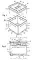
- Fig. 1 in räumlicher Sprengdarstellung die wesentlichen Bestandteile eines Bausatzes für Podeste, Sockel oder dgl. zur Warenpräsentation,
- Fig. 2 in Seitenansicht entsprechend dem Pfeil II in Fig. 1 die wesentlichen Bestandteile des Bausatzes für Podeste, Sockel oder dgl. teilweise im Schnitt,
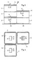
- Fig. 3 in Seitenansicht ein Podest oder einen Sockel, daß bzw. der unter Benutzung des Bausatzes nach den Fig. 1 und 2 erstellt ist,
- Fig. 4 eine Draufsicht in Pfeilrichtung IV der Fig. 3 auf das Podest bzw. den Sockel,
- Fig. 5 in Seitenansicht einen in seinem Aufbau gegenüber den Fig. 3 und 4 abgewandelten Sockel und
- Fig. 6 eine Draufsicht in Pfeilrichtung VI auf den Sockel nach Fig. 5.
- 1 is a three-dimensional exploded view of the essential components of a kit for pedestals, plinths or the like for the presentation of goods,
- 2 in side view according to arrow II in Fig. 1, the essential components of the kit for pedestals, plinths or the like.
- 3 is a side view of a pedestal or a base that is created using the kit according to FIGS. 1 and 2,
- 4 is a plan view in the direction of arrow IV of FIG. 3 on the pedestal or the base,
- Fig. 5 in side view of a modified base compared to FIGS. 3 and 4 and
- 6 is a plan view in the direction of arrow VI on the base of FIG .. 5
In den Fig. 1 und 2 der Zeichnung ist ein Bausatz 1 gezeigt, der sich für die Erstellung von Podesten, Sockeln oder dgl. zur Warenpräsentation, insbesondere bei Verkaufsausstellungen z. B. auf Messen, in Warenhäusem oder dgl., eignet. Er umfaßt eine beliebige Anzahl baugleicher und einstückig aus Kunststoff gefertigter Formkörper 2, die mindestens aufrechte und ring-oder rahmenartig miteinander verbundene Wände 3 haben, welche jeweils zwei parallel zueinander verlaufende Begrenzungsränder 4 und 5 aufweisen. Entlang einem dieser beiden Begrenzungsränder 4 und 5, bspw. im Anschluß an den unteren Begrenzungsrand 5, ist der vorzugsweise durch Spritzgießen aus Kunststoff gefertigte Formkörper 2 mit einem falzartig eingezogenen Absatz 6 versehen, dessen Außenabmessungen 7 auf die Innenabmessungen 8 des Formkörpers 2 im Bereich seines anderen Begrenzungsrandes 4 abgestimmt sind, wie das deutlich aus Fig.2 hervorgeht. Mehrere baugleiche Formkörper 2 lassen sich daher zur Bildung von Podesten, Sockeln oder dgl. übereinandersetzen, dergestalt, daß sie im Bereich ihrer Begrenzungsränder 4 und 5 miteinander kuppelbar sind, indem nämlich der falzartige Absatz 6 des einen Formkörpers im Bereich des Begrenzungsrandes 4 des anderen Formkörpers zum Eingriff kommt. Der Formkörper 2 des Bausatzes 1 nach den Fig. 1 und 2 hat bspw. quadratischen Grundriß, wobei die Eckbereiche seiner Wände 3 mit Abrundungen 9 versehen sind, wie das deutlich Fig. 1 entnommen werden kann.1 and 2 of the drawing, a kit 1 is shown, which is suitable for the creation of pedestals, bases or the like. For the presentation of goods, in particular for sales exhibitions such. B. at trade fairs, in department stores or the like. Suitable. It comprises any number of identical molded
Es besteht ohne weiteres die Möglichkeit, die Formkörper 2, bspw. in Höhe ihres falzartig eingezogenen Absatzes 6 mit einem eingeformten Boden zu versehen, so daß die Formkörper 2 als Gefäße ausgebildet sind. Es ist dann nämlich ohne weiteres möglich, als Formkörper 2 an sich bekannte Pflanz- bzw. Blumenkübel zu benutzen, wie sie in vielfältigen Raumformen in Großserie kostengünstig hergestellt werden. Der in den Fig. 1 und 2 der Zeichnung dargestellte Formkörper 2 weist jedoch in Höhe des falzartig eingezogenen Absatzes 6 keinen Boden auf, d. h. er ist in Richtung seiner Längsachse durchgehend offen ausgestaltet.It is readily possible to provide the molded
Zu dem in den Fig. 1 und 2 gezeigten Bausatz für Podeste, Sockel oder dgl. zur Warenpräsentation gehört außer dem gewissermaßen kastenartig gestalteten Haupt-Formkörper 2 ; noch ein zusätzlicher, plattenartiger Formkörper 10, weicher längs seines Umfanges ebenfalls mit einem falzartig eingezogenen Absatz 11 ausgestattet ist, dessen Außenabmessungen 12 auf die Innenabmessungen 8 des Haupt-Formkörpers 2, wie auch auf die Innenabmessungen 13 am gegenüberliegenden Ende des plattenartigen Zusatz-Formkörpers 10 abgestimmt sind, wie das Fig. 2 ohne weiteres erkennen läßt. Der plattenartige Zusatz-Formkörper 10 ist in Höhe seines falzartig eingezogenen Absatzes 11 grundsätzlich mit einer eingeformten Wand 14 versehen, so daß er sich formschlüssig und deckelartig auf einen Haupt-Formkörper 2 aufsetzen läßt. Die Zusatz-Formkörper 10 sind ebenfalls einstückig aus Kunststoff gefertigt und es besteht ohne weiteres die Möglichkeit, auch mehrere Zusatz-Formkörper 10 stapelartig aufeinander zu setzen, falls dies erwünscht ist. Die Wand 14 des plattenartigen Zusatz-Formkörpers 10 ist mit einer eingeformten, bspw. rechteckig begrenzten Öffnung 15 versehen und entlang einem Begrenzungsrand dieser Öffnung ist unterseitig eine stufenartig abgesetzte Einformung 16 vorhanden. Diese stufenartige Einformung 16 ist dabei an wenigstens zwei rechtwinklig zueinanderliegenden Seiten offen, wobei die eine Seite durch die Öffnung 15 der Wand 14 bestimmt ist.The kit shown in FIGS. 1 and 2 for pedestals, bases or the like for the presentation of goods includes, in addition to the box-shaped main molded
In Fig. 2 ist dabei angedeutet, daß die in der Wand 14 liegende Öffnung 15 mittels eines Deckels 17, insbesondere eines Klappdeckels, wenigstens weitestgehend verschließbar ist, also höchstens eine spaltartige Öffnung 18 frei bleibt, wie das deutlich aus Fig. 4 hervorgeht.In Fig. 2 it is indicated that the opening 15 in the
Die stufenartig vertiefte Einformung 16 im Zusatz-Formkörper kann als Aufnahme für Energiezuführungs-Kupplungen, z. B. elektrische Steckdosen. 19 dienen, wie dies in den Fig. 3 und 4 angedeutet ist. Als Energiezuführungs-Kupplungen können aber auch Druckgas- bzw. Druckflüssigkeitsanschlüsse vorgesehen werden.The step-like
Mindestens für die Haupt-Formkörper 2 des Bausatzes 1 ist noch zu empfehlen, im Bereich des den falzartig eingezogenen Absatz 6 aufweisenden Begrenzungsrandes 5 Ausklinkungen 20 vorzusehen, die als Durchlässe für Energie-Zuführungsleitungen, z. B. Elektrokabel und/oder Gas- bzw. Flüssigkeitsschläuche, zu versehen. Einerseits ist hierdurch sichergestellt, daß die Energie-Zuführungsleitungen nicht durch die Kanten der Formkörper 2 beschädigt werden. Andererseits wird aber auch die Standsicherheit der Formkörper 2 auf dem Boden nicht beeinträchtigt.At least for the main molded
In manchen Fällen kann es sich noch als zweckmäßig erweisen, die Wände 3 der Haupt-Formkörper 2 mit Schlitzen 21 zu versehen, wie das in den Fig. 1 und 2 durch strichpunktierte Linien angedeutet ist.In some cases, it can also be expedient to provide the
Obwohl die Möglichkeit besteht, diese Schlitze 21 vertikal ausgerichtet in den Wänden 3 zu ordnen, hat es sich besonders bewährt, sie in horizontaler Lage vorzusehen.Although it is possible to arrange these
Die Schlitze 21 können als Halteeingriffe für einen Begrenzungsrand von flachen Platten 22, insbesondere Glasplatten, benutzt werden, welche als seitwärts frei auskragende Warenträger mit den Haupt-Formkörpem 2 gekuppelt werden können, wie das in den Fig. 5 und 6 angedeutet ist.The
Falls sie Schlitze 21 mit vertikaler Ausrichtung in den Wänden 3 der Haupt-Formkörper 2 vorgesehen werden, können die mit ihnen in Halteeingriff zu bringenden, flachen Platten auch als Distanzglieder zwischen zwei im Abstand nebeneinander angeordneten Haupt-Formkörpem 2 benutzt werden.If
Empfehlenswert ist es, die in die Schlitze 21 einrückbaren Platten 22 jeweils in ihren Ecken mit einer Abschrägung auszustatten, so daß dort stumpfwinklig ineinander übergehende Begrenzungskanten entstehen, wie das Fig. 6 deutlich erkennen läßt.It is advisable to equip the
Bei den in den Fig. 1 bis 6 dargestellten Ausführungsbeispielen eines Bausatzes 1 für Podeste, Sockel oder dgl. haben die Haupt-Formkörper 2 und die Zusatz-Formkörper 10 jeweils quadratischen Grundriß. Selbstverständlich liegt es aber auch im Rahmen der Neuerung, den Haupt-Formkörpem 2 und den Zusatz-Formkörpern 10 einen anderen polygonförmigen Grundriß zu geben; sie bspw. also dreieckig, rechteckig oder auch sechseckig zu begrenzen. Eine runde, ovale oder auch langrunde Grundrißgestaltung liegt ebenfalls im Rahmen der Möglichkeiten.In the exemplary embodiments of a kit 1 for pedestals, bases or the like shown in FIGS. 1 to 6, the main molded
In manchen Fällen kann es sich auch als zweckmäßig werweisen, die Zusatz-Formkörper 10 auf der Oberseite ihrer Wand 14 mit einem Belag aus Textilmaterial und/oder einem anderen, formweichen Schichtwerkstoff, z. B. Teppich, Filz, Bürstenmaterial oder auch Gummi, zu versehen.In some cases, it may also prove to be expedient to coat the additional molded
Claims (9)
Priority Applications (1)
| Application Number | Priority Date | Filing Date | Title |
|---|---|---|---|
| AT85112950T ATE45870T1 (en) | 1984-10-27 | 1985-10-11 | KIT FOR PLATFORMS, BASES OR THE LIKE. FOR GOODS PRESENTATION. |
Applications Claiming Priority (2)
| Application Number | Priority Date | Filing Date | Title |
|---|---|---|---|
| DE8431566U | 1984-10-27 | ||
| DE19848431566U DE8431566U1 (en) | 1984-10-27 | 1984-10-27 | KIT FOR PODES, BASE OD. DGL. GOODS PRESENTATION |
Publications (3)
| Publication Number | Publication Date |
|---|---|
| EP0180079A2 EP0180079A2 (en) | 1986-05-07 |
| EP0180079A3 EP0180079A3 (en) | 1987-04-01 |
| EP0180079B1 true EP0180079B1 (en) | 1989-08-30 |
Family
ID=6772131
Family Applications (1)
| Application Number | Title | Priority Date | Filing Date |
|---|---|---|---|
| EP85112950A Expired EP0180079B1 (en) | 1984-10-27 | 1985-10-11 | Construction element for a platform, pedestal or the like for displaying merchandise |
Country Status (3)
| Country | Link |
|---|---|
| EP (1) | EP0180079B1 (en) |
| AT (1) | ATE45870T1 (en) |
| DE (2) | DE8431566U1 (en) |
Families Citing this family (4)
| Publication number | Priority date | Publication date | Assignee | Title |
|---|---|---|---|---|
| US4927106A (en) * | 1987-09-07 | 1990-05-22 | Daimler-Benz Aktiengesellschaft | Presentation podium |
| DE3828164A1 (en) * | 1987-09-07 | 1989-03-16 | Daimler Benz Ag | PRESENTATION PODEST |
| GB2379649A (en) * | 2001-06-14 | 2003-03-19 | Stephen Keyes | Paint roller tray and stand |
| CN103640750B (en) * | 2013-12-14 | 2016-06-29 | 金文日 | Beauty treatment ornaments packaging and display box that a kind of plastic uptake combines with injection moulding and box group |
Family Cites Families (7)
| Publication number | Priority date | Publication date | Assignee | Title |
|---|---|---|---|---|
| GB191100217A (en) * | 1911-01-04 | 1911-05-04 | Edward Stephen Cashen | Improvements in and relating to Adjustable Show Stands. |
| FR809004A (en) * | 1936-08-05 | 1937-02-22 | Coated plinth or tray system | |
| DE1609899C3 (en) * | 1966-11-12 | 1980-02-07 | Georg 7520 Bruchsal Wagner | Multi-part component for creating boxes and buckets |
| GB1288368A (en) * | 1970-11-23 | 1972-09-06 | ||
| ZA723816B (en) * | 1971-06-26 | 1974-01-30 | Colgate Palmolive Co | Display stand |
| FR2229304A5 (en) * | 1973-05-09 | 1974-12-06 | Seiller Pierre | Modular element for display and lighting - recesses and slotted projections allow stacking and may be packed flat |
| DE8510722U1 (en) * | 1985-04-12 | 1985-05-30 | Egon Hillebrand Gmbh & Co, 5760 Arnsberg | Work table for electrical equipment |
-
1984
- 1984-10-27 DE DE19848431566U patent/DE8431566U1/en not_active Expired
-
1985
- 1985-10-11 EP EP85112950A patent/EP0180079B1/en not_active Expired
- 1985-10-11 DE DE8585112950T patent/DE3572585D1/en not_active Expired
- 1985-10-11 AT AT85112950T patent/ATE45870T1/en not_active IP Right Cessation
Also Published As
| Publication number | Publication date |
|---|---|
| DE8431566U1 (en) | 1985-02-28 |
| EP0180079A2 (en) | 1986-05-07 |
| ATE45870T1 (en) | 1989-09-15 |
| EP0180079A3 (en) | 1987-04-01 |
| DE3572585D1 (en) | 1989-10-05 |
Similar Documents
| Publication | Publication Date | Title |
|---|---|---|
| EP0180079B1 (en) | Construction element for a platform, pedestal or the like for displaying merchandise | |
| DE202010003764U1 (en) | Connector module for juxtaposed sales containers and the resulting system | |
| DE2444648A1 (en) | COMPONENT | |
| EP0120099B1 (en) | Display tray for merchandise | |
| DE2300675C2 (en) | Box element for shelf structures | |
| DE6604982U (en) | MULTIPLE KINDS OF COMPOSITIONABLE CASSETTE MADE OF PLASTIC MATERIAL OR OF ANY OTHER EQUIVALENT MATERIAL ESPECIALLY SUITABLE FOR STORING LOTS OF GENERAL TYPES | |
| CH662241A5 (en) | Polygonal planting container with covering | |
| DE8025774U1 (en) | Built-in housing | |
| DE1960113A1 (en) | Box made of plastic with trapezoidal walls | |
| DE1929069C3 (en) | Edging for lawn edges | |
| DE19619633C1 (en) | Adaptors for attaching advertising material to pallets | |
| DE202016006632U1 (en) | Kit for exhibition purposes | |
| DE2546344A1 (en) | Model construction kit for houses - has base plate with equally spaced slots on upper side to hold wall elements | |
| EP0118032A2 (en) | Device for displaying the numerical build-up and size of masses | |
| DE2230551C3 (en) | Office stationery tray | |
| DE3329409C2 (en) | Device for raising planters | |
| EP0430120B1 (en) | Stackable module | |
| EP4321059A1 (en) | Display device | |
| CH587001A5 (en) | Plant or flower container - features three identical modular frames with interlocking guide channels (OE 15.8.75) | |
| DE202017106698U1 (en) | Planters panel | |
| DE102005043353A1 (en) | Refrigerating appliance with storage | |
| DE3642520A1 (en) | Packaging container | |
| DE3926171A1 (en) | SALES STAND | |
| DE4301222A1 (en) | Building blocks for erection of esp. office dividing walls | |
| EP1028407A2 (en) | Advertising support |
Legal Events
| Date | Code | Title | Description |
|---|---|---|---|
| PUAI | Public reference made under article 153(3) epc to a published international application that has entered the european phase |
Free format text: ORIGINAL CODE: 0009012 |
|
| 17P | Request for examination filed |
Effective date: 19851023 |
|
| AK | Designated contracting states |
Kind code of ref document: A2 Designated state(s): AT BE CH DE FR GB IT LI LU NL SE |
|
| PUAL | Search report despatched |
Free format text: ORIGINAL CODE: 0009013 |
|
| AK | Designated contracting states |
Kind code of ref document: A3 Designated state(s): AT BE CH DE FR GB IT LI LU NL SE |
|
| 17Q | First examination report despatched |
Effective date: 19880505 |
|
| GRAA | (expected) grant |
Free format text: ORIGINAL CODE: 0009210 |
|
| AK | Designated contracting states |
Kind code of ref document: B1 Designated state(s): AT BE CH DE FR GB IT LI LU NL SE |
|
| PG25 | Lapsed in a contracting state [announced via postgrant information from national office to epo] |
Ref country code: SE Effective date: 19890830 Ref country code: NL Effective date: 19890830 Ref country code: IT Free format text: LAPSE BECAUSE OF FAILURE TO SUBMIT A TRANSLATION OF THE DESCRIPTION OR TO PAY THE FEE WITHIN THE PRESCRIBED TIME-LIMIT;WARNING: LAPSES OF ITALIAN PATENTS WITH EFFECTIVE DATE BEFORE 2007 MAY HAVE OCCURRED AT ANY TIME BEFORE 2007. THE CORRECT EFFECTIVE DATE MAY BE DIFFERENT FROM THE ONE RECORDED. Effective date: 19890830 Ref country code: GB Effective date: 19890830 Ref country code: FR Free format text: THE PATENT HAS BEEN ANNULLED BY A DECISION OF A NATIONAL AUTHORITY Effective date: 19890830 Ref country code: BE Effective date: 19890830 |
|
| REF | Corresponds to: |
Ref document number: 45870 Country of ref document: AT Date of ref document: 19890915 Kind code of ref document: T |
|
| REF | Corresponds to: |
Ref document number: 3572585 Country of ref document: DE Date of ref document: 19891005 |
|
| PG25 | Lapsed in a contracting state [announced via postgrant information from national office to epo] |
Ref country code: AT Effective date: 19891011 |
|
| PG25 | Lapsed in a contracting state [announced via postgrant information from national office to epo] |
Ref country code: LU Free format text: LAPSE BECAUSE OF NON-PAYMENT OF DUE FEES Effective date: 19891031 Ref country code: LI Effective date: 19891031 Ref country code: CH Effective date: 19891031 |
|
| EN | Fr: translation not filed | ||
| NLV1 | Nl: lapsed or annulled due to failure to fulfill the requirements of art. 29p and 29m of the patents act | ||
| GBV | Gb: ep patent (uk) treated as always having been void in accordance with gb section 77(7)/1977 [no translation filed] | ||
| REG | Reference to a national code |
Ref country code: CH Ref legal event code: PL |
|
| PLBE | No opposition filed within time limit |
Free format text: ORIGINAL CODE: 0009261 |
|
| STAA | Information on the status of an ep patent application or granted ep patent |
Free format text: STATUS: NO OPPOSITION FILED WITHIN TIME LIMIT |
|
| 26N | No opposition filed | ||
| PGFP | Annual fee paid to national office [announced via postgrant information from national office to epo] |
Ref country code: DE Payment date: 19921209 Year of fee payment: 8 |
|
| PG25 | Lapsed in a contracting state [announced via postgrant information from national office to epo] |
Ref country code: DE Effective date: 19940701 |