EP0179484A2 - Treiberschaltkreis vom stromgeregelten Typ für bürstenlosen Motor - Google Patents
Treiberschaltkreis vom stromgeregelten Typ für bürstenlosen Motor Download PDFInfo
- Publication number
- EP0179484A2 EP0179484A2 EP85113586A EP85113586A EP0179484A2 EP 0179484 A2 EP0179484 A2 EP 0179484A2 EP 85113586 A EP85113586 A EP 85113586A EP 85113586 A EP85113586 A EP 85113586A EP 0179484 A2 EP0179484 A2 EP 0179484A2
- Authority
- EP
- European Patent Office
- Prior art keywords
- amplifier
- signal
- current
- error signal
- speed error
- Prior art date
- Legal status (The legal status is an assumption and is not a legal conclusion. Google has not performed a legal analysis and makes no representation as to the accuracy of the status listed.)
- Granted
Links
- 238000001514 detection method Methods 0.000 abstract 2
- 238000004804 winding Methods 0.000 description 9
- 230000001419 dependent effect Effects 0.000 description 3
- 238000010586 diagram Methods 0.000 description 3
Images

Classifications
-
- H—ELECTRICITY
- H02—GENERATION; CONVERSION OR DISTRIBUTION OF ELECTRIC POWER
- H02P—CONTROL OR REGULATION OF ELECTRIC MOTORS, ELECTRIC GENERATORS OR DYNAMO-ELECTRIC CONVERTERS; CONTROLLING TRANSFORMERS, REACTORS OR CHOKE COILS
- H02P6/00—Arrangements for controlling synchronous motors or other dynamo-electric motors using electronic commutation dependent on the rotor position; Electronic commutators therefor
- H02P6/06—Arrangements for speed regulation of a single motor wherein the motor speed is measured and compared with a given physical value so as to adjust the motor speed
Definitions
- the present invention relates to a driver circuit for brushless DC motor and in particlular to a current control type driver circuit suitable to a chopping type driver circuit for controlling the rotation of a motor with a forward torque and a backward torque.
- a chopping type driver circuit for brushless motor such as disclosed in, for example, Japanese Patent Unexamined Publication No. 57-145586
- the speed error signal is detected and the current flowing through the winding of the motor is switched by switching elements on the basis of the detected speed error signal.
- the forward control torque during the rotation is different from the backward control torque during the rotation because of the influence of the speed electromotive force.
- the speed error signal therefore, the number of rotations during rotation is controlled with different torques in the forward direction and in the backward direction. This results in a drawback that the number of rotations cannot be controlled smoothly.
- An object of the present invention is to provide a current control type chopping driver circuit which is free from the above described drawback of the prior art and which makes the forward control torque during the motor rotation equal to the backward control torque.
- the current flowing through the motor winding is detected to apply negative feedback based upon the motor winding current to means for amplifying the speed error signal, whereby equal magnitude of currents are made to flow through the motor winding in the forward control and in the backward control to make the control torque in the forward direction equal to that in the backward direction.
- Fig. 1 is a block diagram of an embodiment according to the present invention.
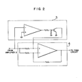
- Fig. 2 is a circuit diagram for illustrating an example of a comparator and that of an inverting-noninverting amplifier shown in
- Reference numeral 1 denotes an error signal detector for speed or phase.
- the reproduced HD signal is compared with the reference HD signal and detected to produce a speed/ phase error signal.
- An amplifier 2 is provided for the purpose of current feedback.
- the error signal is supplied to the noninverting input of the amplifier 2 and the current feedback signal is supplied to the inverting input of the amplifier 2.
- a comparator 3 compares the output of the amplifier 2 with the zero potential to produce the logic level "L” when the output of the amplifier 2 is positive and the logic level "H” when the output of the amplifier 2 is negative.
- an amplifier 4 amplifies the output of the amplifier 2 in either inverting mode or in the noninverting mode according to the output of the comparator 3.
- the amplifier 4 serves as a noninverting amplifier when the output of the comparator assumes the logic level "L” and serves as an inverting amplifier when the output of the comparator assumes the logic level "H”. Therefore, the output of the amplifier 4 always becomes positive or zero.
- a PWM circuit 5 applies pulse width modulation to the output of of the amplifier 4.
- the pulse width modulated error signal opens or closes a switch 7 to chop the current flowing from the power supply 6 to the motor.
- a Hall device application current changeover circuit 8 changes over the direction of the current applied to the Hall device.
- the direction of the current is so changed that a torque generates which accelerates the rotation of the motor in the forward direction when the output of the comparator 3 assumes the logic level "L” and a torque generates which decelerates the rotation of the motor in the backward direction when the comparator 3 assumes the logic level "H”.
- Each of Hall devices 9a to 9c for detecting the rotational position defines the direction of the current flowing through the stator coil.
- the current of Hall devices 9a, 9b and 9c is shifted in phase by 120° with respect to 9b, 9c and 9a, respectively.
- Each of the Hall devices 9a to 9c generates voltage dependent upon the polarity of the current supplied from the changeover circuit 8 and the rotary field.
- Each of switch pairs lla to llc is composed of two switches which assume on/off states opposing each other and is placed in the current path of associated one of the stator coils 12a to 12c.
- Each of these switch pairs can be realized by a PNP transistor and an NPN transistor, for example.
- the base of the PNP transistor is connected to that of the NPN transistor to form the input.
- the emitter of the PNP transistor is connected to that of the NPN transistor to form the output.
- the collector of the PNP transistor is connected to the side of the resistor 13.
- the collector of the NPN transistor is connected to the side of the switch 7.
- the stator coils 12a to 12c are coupled in the Y connection, they may be coupled in the delta connection.
- the resistor 13 converts the current flowing through each of stator coild 12a to 12c into a voltage value.
- An amplifier 14 serves as an inverting amplifier or a noninverting amplifier accord- ing to the output of the comparator 3.
- the negative feedback to the speed error signal is conducted in the form of the winding current of the motor, chopping dependent upon the current flowing through the motor winding is carried out for the current control. Since the motor torque is in proportion to the winding current, the influence of the speed electromotive force is eliminated. As a result, linear torque control with respect to the speed error signal becomes possible.
Landscapes
- Engineering & Computer Science (AREA)
- Power Engineering (AREA)
- Control Of Motors That Do Not Use Commutators (AREA)
Applications Claiming Priority (2)
| Application Number | Priority Date | Filing Date | Title |
|---|---|---|---|
| JP223953/84 | 1984-10-26 | ||
| JP59223953A JPS61106088A (ja) | 1984-10-26 | 1984-10-26 | ブラシレスモ−タの電流制御駆動回路 |
Publications (3)
| Publication Number | Publication Date |
|---|---|
| EP0179484A2 true EP0179484A2 (de) | 1986-04-30 |
| EP0179484A3 EP0179484A3 (en) | 1987-08-19 |
| EP0179484B1 EP0179484B1 (de) | 1991-02-27 |
Family
ID=16806281
Family Applications (1)
| Application Number | Title | Priority Date | Filing Date |
|---|---|---|---|
| EP85113586A Expired EP0179484B1 (de) | 1984-10-26 | 1985-10-25 | Treiberschaltkreis vom stromgeregelten Typ für bürstenlosen Motor |
Country Status (4)
| Country | Link |
|---|---|
| US (1) | US4631458A (de) |
| EP (1) | EP0179484B1 (de) |
| JP (1) | JPS61106088A (de) |
| DE (1) | DE3581877D1 (de) |
Cited By (3)
| Publication number | Priority date | Publication date | Assignee | Title |
|---|---|---|---|---|
| GB2199167B (en) * | 1986-11-29 | 1991-02-20 | Papst Motoren Gmbh & Co Kg | Rotary drive for a data storage medium |
| GB2243504A (en) * | 1990-03-07 | 1991-10-30 | Matsushita Electric Industrial Co Ltd | Drive apparatus and speed control apparatus for brushless motor |
| EP0608769A3 (de) * | 1993-01-21 | 1996-03-06 | Fujitsu General Ltd | Kontrolleinrichtung für Luftkonditionierer. |
Families Citing this family (19)
| Publication number | Priority date | Publication date | Assignee | Title |
|---|---|---|---|---|
| US5023527A (en) | 1974-06-24 | 1991-06-11 | General Electric Company | Control circuits, electronically commutated motor systems and methods |
| US4763347A (en) * | 1983-02-02 | 1988-08-09 | General Electric Company | Control system, electronically commutated motor system, blower apparatus and methods |
| JPS6237093A (ja) * | 1985-08-07 | 1987-02-18 | Hitachi Ltd | 空気調和機用圧縮機の制御装置 |
| FR2590420B1 (fr) * | 1985-11-21 | 1994-04-08 | Valeo | Dispositif limiteur du courant d'alimentation pour un moteur electrique a courant continu, et moteur electrique equipe d'un tel dispositif |
| SE457307B (sv) * | 1986-06-17 | 1988-12-12 | Ems Electronic Motor Systems | Foerfarande och anordning foer reglering av en borstloes likstroemsmotor |
| US4902944A (en) * | 1986-11-20 | 1990-02-20 | Staubli International Ag. | Digital robot control having an improved current sensing system for power amplifiers in a digital robot control |
| US4763052A (en) * | 1987-06-25 | 1988-08-09 | The Superior Electric Company | Method and means for driving a brushless D.C. motor |
| US5012167A (en) * | 1987-11-03 | 1991-04-30 | Penn Engineering & Manufacturing Corp. | Sinusoidal signal decoder for 12-step motor commutation |
| JPH0750880Y2 (ja) * | 1988-09-29 | 1995-11-15 | 株式会社三協精機製作所 | ブラシレスモータの駆動回路 |
| US4949021A (en) * | 1988-11-14 | 1990-08-14 | Sunstrand Corporation | Variable speed constant frequency start system with selectable input power limiting |
| US5142208A (en) * | 1991-07-26 | 1992-08-25 | Storage Technology Corporation | Current sensing method and apparatus for a multi-phase brushless DC motor |
| US5532787A (en) * | 1993-10-14 | 1996-07-02 | Fuji Photo Film Co., Ltd. | Photographic printing shutter |
| US5929577A (en) * | 1995-10-13 | 1999-07-27 | Unitrode Corporation | Brushless DC motor controller |
| KR100357873B1 (ko) * | 1997-12-31 | 2003-01-10 | 삼성전자 주식회사 | 광디스크재생장치의모터회전제어장치 |
| US6476577B1 (en) * | 1999-09-22 | 2002-11-05 | Visteon Global Tech., Inc. | Motor control circuit |
| US6344720B1 (en) * | 1999-10-28 | 2002-02-05 | International Business Machines Corporation | Current mode PWM technique for a brushless motor |
| DE60135149D1 (de) | 2000-12-30 | 2008-09-11 | Hamilton Sundstrand Corp | Schaltsteuersystem und drehzahlregelung für einen bürstenlosen motor |
| US6903523B2 (en) * | 2003-06-04 | 2005-06-07 | William A. Peterson | Methods and apparatus for dynamically reconfiguring a pulse width modulation approach |
| US7321210B2 (en) * | 2005-04-05 | 2008-01-22 | International Rectifier Corporation | Sensorless brushless direct current motor drive using pulse width modulation speed control at motor frequency |
Family Cites Families (10)
| Publication number | Priority date | Publication date | Assignee | Title |
|---|---|---|---|---|
| JPS51610A (en) * | 1974-06-24 | 1976-01-06 | Canon Kk | Hoorumootaano kudokairo |
| DE2516804C3 (de) * | 1975-04-16 | 1982-05-27 | Nixdorf Computer Ag, 4790 Paderborn | Schaltungsanordnung zur Drehzahlregelung eines kollektorlosen Gleichstrommotors |
| JPS5243924A (en) * | 1975-10-02 | 1977-04-06 | Pioneer Electronic Corp | Direct current motor without commutator |
| JPS5364711A (en) * | 1976-11-19 | 1978-06-09 | Sony Corp | Brushless motor drive circuit |
| SU664265A1 (ru) * | 1977-06-13 | 1979-05-25 | Московский Ордена Трудового Красного Знамени Текстильный Институт | Вентильный электродвигатель |
| JPS58159687A (ja) * | 1982-03-18 | 1983-09-22 | Trio Kenwood Corp | 2相ブラシレスモ−タ− |
| DE3210354C2 (de) * | 1982-03-20 | 1985-07-18 | Arthur Pfeiffer Vakuumtechnik Wetzlar Gmbh, 6334 Asslar | Antrieb für Turbomolekularpumpen |
| JPS5932381A (ja) * | 1982-08-17 | 1984-02-21 | Toshiba Corp | 誘導電動機の制御装置 |
| US4472666A (en) * | 1982-09-21 | 1984-09-18 | Matsushita Electric Industrial Co., Ltd. | Brushless DC motor |
| JPS59149782A (ja) * | 1983-02-16 | 1984-08-27 | Hitachi Ltd | 空気調和装置の負荷軽減装置 |
-
1984
- 1984-10-26 JP JP59223953A patent/JPS61106088A/ja active Pending
-
1985
- 1985-10-25 EP EP85113586A patent/EP0179484B1/de not_active Expired
- 1985-10-25 US US06/791,344 patent/US4631458A/en not_active Expired - Fee Related
- 1985-10-25 DE DE8585113586T patent/DE3581877D1/de not_active Expired - Lifetime
Cited By (8)
| Publication number | Priority date | Publication date | Assignee | Title |
|---|---|---|---|---|
| GB2199167B (en) * | 1986-11-29 | 1991-02-20 | Papst Motoren Gmbh & Co Kg | Rotary drive for a data storage medium |
| US5317241A (en) * | 1986-11-29 | 1994-05-31 | Papst Licensing Gmbh | Rotary drive for a data carrier |
| USRE37825E1 (en) | 1986-11-29 | 2002-09-03 | Papst Licensing Gmbh & Co. Kg | Data storage device having a drive mechanism for rotating a data storage medium |
| USRE38264E1 (en) | 1986-11-29 | 2003-10-07 | Papst Licensing Gmbh & Co. Kg | Rotary drive for a data carrier |
| GB2243504A (en) * | 1990-03-07 | 1991-10-30 | Matsushita Electric Industrial Co Ltd | Drive apparatus and speed control apparatus for brushless motor |
| US5300866A (en) * | 1990-03-07 | 1994-04-05 | Matsushita Electric Industrial Co., Ltd. | Drive apparatus and speed control apparatus for brushless motor |
| GB2243504B (en) * | 1990-03-07 | 1994-08-31 | Matsushita Electric Industrial Co Ltd | Drive apparatus for brushless motor |
| EP0608769A3 (de) * | 1993-01-21 | 1996-03-06 | Fujitsu General Ltd | Kontrolleinrichtung für Luftkonditionierer. |
Also Published As
| Publication number | Publication date |
|---|---|
| EP0179484A3 (en) | 1987-08-19 |
| EP0179484B1 (de) | 1991-02-27 |
| US4631458A (en) | 1986-12-23 |
| JPS61106088A (ja) | 1986-05-24 |
| DE3581877D1 (de) | 1991-04-04 |
Similar Documents
| Publication | Publication Date | Title |
|---|---|---|
| EP0179484A2 (de) | Treiberschaltkreis vom stromgeregelten Typ für bürstenlosen Motor | |
| US5204594A (en) | Circuit for providing a signal proportional to the average current flowing through coils of a motor operated in both linear and PWM modes | |
| EP0123807B1 (de) | Antrieb und Feststellung von Gegen-EMK in Dauermagnetschrittmotoren | |
| US4135120A (en) | Drive circuit for a brushless motor | |
| US5541484A (en) | BLDCM phase current reconstruction circuit | |
| JPH0239199B2 (de) | ||
| US4306181A (en) | Drive circuitry for electric motor | |
| JPH0728553B2 (ja) | モータの駆動回路 | |
| US4066935A (en) | Stator winding control circuit for a brushless d.c. motor | |
| JP2005039955A (ja) | ステッピングモータの駆動方法および制御装置 | |
| US6184645B1 (en) | Voltage mode drive for control circuit for an actuator using sampled back EMF control | |
| US3959700A (en) | Speed control device for transistor motor | |
| GB2095931A (en) | Brushless dc motor control circuits | |
| US5874814A (en) | Brushless motor driven by applying varying driving signals | |
| JP2583443B2 (ja) | 直流電動機の回転トルク検出装置 | |
| US5910717A (en) | Circuit arrangement for controlling a reversible D.C. motor | |
| JPS6111555B2 (de) | ||
| KR860001001Y1 (ko) | 캡스턴 모우터 제어회로 | |
| JP2594040B2 (ja) | モータ制御回路 | |
| JPH0717280Y2 (ja) | ホ−ルモ−タ駆動回路 | |
| JPH0527351B2 (de) | ||
| JPS622960Y2 (de) | ||
| JPH0347439Y2 (de) | ||
| JPS61218391A (ja) | モ−タ制御装置 | |
| KR0134789Y1 (ko) | 브러시리스 모터 |
Legal Events
| Date | Code | Title | Description |
|---|---|---|---|
| PUAI | Public reference made under article 153(3) epc to a published international application that has entered the european phase |
Free format text: ORIGINAL CODE: 0009012 |
|
| 17P | Request for examination filed |
Effective date: 19851025 |
|
| AK | Designated contracting states |
Kind code of ref document: A2 Designated state(s): DE NL |
|
| PUAL | Search report despatched |
Free format text: ORIGINAL CODE: 0009013 |
|
| AK | Designated contracting states |
Kind code of ref document: A3 Designated state(s): DE NL |
|
| 17Q | First examination report despatched |
Effective date: 19891123 |
|
| GRAA | (expected) grant |
Free format text: ORIGINAL CODE: 0009210 |
|
| AK | Designated contracting states |
Kind code of ref document: B1 Designated state(s): DE NL |
|
| REF | Corresponds to: |
Ref document number: 3581877 Country of ref document: DE Date of ref document: 19910404 |
|
| PLBE | No opposition filed within time limit |
Free format text: ORIGINAL CODE: 0009261 |
|
| STAA | Information on the status of an ep patent application or granted ep patent |
Free format text: STATUS: NO OPPOSITION FILED WITHIN TIME LIMIT |
|
| 26N | No opposition filed | ||
| PGFP | Annual fee paid to national office [announced via postgrant information from national office to epo] |
Ref country code: NL Payment date: 19941031 Year of fee payment: 10 |
|
| PGFP | Annual fee paid to national office [announced via postgrant information from national office to epo] |
Ref country code: DE Payment date: 19941124 Year of fee payment: 10 |
|
| PG25 | Lapsed in a contracting state [announced via postgrant information from national office to epo] |
Ref country code: NL Effective date: 19960501 |
|
| PG25 | Lapsed in a contracting state [announced via postgrant information from national office to epo] |
Ref country code: DE Effective date: 19960702 |
|
| NLV4 | Nl: lapsed or anulled due to non-payment of the annual fee |
Effective date: 19960501 |