EP0179341A2 - Verfahren und Einrichtung zur Abstandskontrolle eines in einer Behälterstruktur bewerkstelligten Prozesses - Google Patents
Verfahren und Einrichtung zur Abstandskontrolle eines in einer Behälterstruktur bewerkstelligten Prozesses Download PDFInfo
- Publication number
- EP0179341A2 EP0179341A2 EP85112635A EP85112635A EP0179341A2 EP 0179341 A2 EP0179341 A2 EP 0179341A2 EP 85112635 A EP85112635 A EP 85112635A EP 85112635 A EP85112635 A EP 85112635A EP 0179341 A2 EP0179341 A2 EP 0179341A2
- Authority
- EP
- European Patent Office
- Prior art keywords
- redundant
- containment structure
- detector signals
- signals
- detector
- Prior art date
- Legal status (The legal status is an assumption and is not a legal conclusion. Google has not performed a legal analysis and makes no representation as to the accuracy of the status listed.)
- Granted
Links
Images


Classifications
-
- G—PHYSICS
- G21—NUCLEAR PHYSICS; NUCLEAR ENGINEERING
- G21C—NUCLEAR REACTORS
- G21C17/00—Monitoring; Testing ; Maintaining
- G21C17/10—Structural combination of fuel element, control rod, reactor core, or moderator structure with sensitive instruments, e.g. for measuring radioactivity, strain
-
- G—PHYSICS
- G21—NUCLEAR PHYSICS; NUCLEAR ENGINEERING
- G21C—NUCLEAR REACTORS
- G21C17/00—Monitoring; Testing ; Maintaining
- G21C17/10—Structural combination of fuel element, control rod, reactor core, or moderator structure with sensitive instruments, e.g. for measuring radioactivity, strain
- G21C17/12—Sensitive element forming part of control element
-
- Y—GENERAL TAGGING OF NEW TECHNOLOGICAL DEVELOPMENTS; GENERAL TAGGING OF CROSS-SECTIONAL TECHNOLOGIES SPANNING OVER SEVERAL SECTIONS OF THE IPC; TECHNICAL SUBJECTS COVERED BY FORMER USPC CROSS-REFERENCE ART COLLECTIONS [XRACs] AND DIGESTS
- Y02—TECHNOLOGIES OR APPLICATIONS FOR MITIGATION OR ADAPTATION AGAINST CLIMATE CHANGE
- Y02E—REDUCTION OF GREENHOUSE GAS [GHG] EMISSIONS, RELATED TO ENERGY GENERATION, TRANSMISSION OR DISTRIBUTION
- Y02E30/00—Energy generation of nuclear origin
- Y02E30/30—Nuclear fission reactors
Definitions
- This invention is directed to a method and apparatus for remotely monitoring with high reliability a process carried out in a hazardous environment within a containment structure. More particularly, it is directed to a method and apparatus for transmitting redundant signals from a large number of detectors through the containment structure with a minimum number of penetrations. It is particularly applicable to transmitting to the plant control room outside of the containment building reliable indications of control rod position in a nuclear reactor.
- a nuclear reactor is an example of an installation in which hundreds of detectors and control signals of various kinds must be transmitted through the containment structure for monitoring, protection, and control functions directed from outside. Remotely monitoring the position of the control rods within the core of the nuclear reactor is a procedure which requires the transmission of a great deal of information through the containment structure.
- Reliability is of critical importance in monitoring the position of control rods in the core of a nuclear reactor. It is well-known that reliability can be enhanced through redundancy.
- redundant sets of coils are interleaved along the path of each drive rod and the signals generated as the end of the rod passes through the coils in each set are separately transmitted through the containment building wall through separate channels to the outside where they are combined to provide an indication of rod position. All of the data generated by one set of coils in each detector is transmitted over one channel and that generated by the second set of coils in each detector is transmitted over another channel.
- the remaining channel provides the position indication for all of the rods with half the resolution of the combined indication. While such systems provide protection against a single component failure, they are highly susceptible to certain dual component failures. For instance, if one transmission channel should fail, the signals from one entire set of coils for each detector are not available. A subsequent failure in the other set of coils for any detector results in a loss of all reliable information regarding the position of the neutron absorbing rods connected to the associated drive rod.
- the invention in its broad form comprises apparatus for transmitting signals generated by a plurality of detectors located in use in a hazardous environment enclosed within a containment structure to the outside of the containment structure, said apparatus comprising: means within the containment structure for generating a plurality of redundant sets of digital detector signals; a plurality of redundant communications buses located .within the containment structure; the apparatus characterized by interface means within the containment structure for selectively applying each set of the redundant digital detector signals to each of the redundant communications buses; a plurality of bus controller/serial output devices in the containment structure, each of which is connected to one of said communications buses for controlling said interface means in applying said redundant sets of digital detector signals to the associated communications bus, and for serially putting out the redundant sets of digital detector signals received over the associated communications bus; serial data link means connected to each of said bus controller/serial output devices within the containment structure and extending through the containment structure to the outside thereof; and receiver means outside of said containment structure connected to said serial data link means, for receiving said redundant sets of digital detector signals serial
- the apparatus used to carry out the invention includes means within the containment structure for generating a plurality of redundant sets of detector signals.
- Interface means applies all of the redundant signals to each of a plurality of communications buses equal in number to the number of redundant sets of signals.
- a plurality of bus controller/serial output devices located in the containment structure are each connected to one of the communications buses, to control the interface means in applying the redundant sets of detector signals to the associated communications bus, to store these signals, and to serially output them over its own data link extending through the containment structure to the outside.
- Redundant receiver devices on the outside of the containment structure generate from the redundant sets of detector signals received from one of the data links, a representation of the value of the detector signal.
- Switching means permit selection of the data link from which each receiver receives its redundant sets of detector signals and permits individual selection as to each detector of which of the redundant signal is to be used in generating the representation of the value of that detector signal.
- the detector signals are generated as multi-digit digital signals from the signals generated by the discrete coils spaced along the travel path of the rod.
- the redundant signals can be generated simply by reproducing the coil signals, since these components have been proven to be very dependable.
- interleaved redundant sets of coils can be used to produce the redundant detector signals.
- the essence of the invention is that all of the redundant signals are all transmitted over all of the redundant transmission channels with each of the receivers being able to select the individual channel from which it receives the redundant signals.
- failure of the same component in each of the detector to display channels is required to cause a loss of any of the transmitted information thus providing increased reliability over the earlier systems in which the redundant signals were transmitted separately over independent transmission channels.
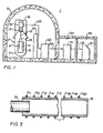
- the invention will be described as applied to a rod position monitoring system for the pressurized water reactor (PWR) shown in Figure 1 although it is to be understood that the invention has broader application to instrumentation generally for nuclear reactors, and even more broadly, to remote control and monitoring of other processes carried out in a hazardous environment inside a containment structure.
- the PWR 1 of Figure 1 includes a nuclear reactor 3 enclosed within a containment building 5 which prevents the escape of most radiation generated by the reactor.
- the reactor 3 includes a reactor vessel 7 housing a core 9 of fissile material having hundreds of neutron absorbing rods 11 which control the reactivity of the core.
- neutron absorbing rods 11 include: control rods which are moved in and out of the core to regulate the power level of the reactor, shutdown rods which are either all the way in when the reactor is shutdown or all the way out when it is at power, and part-length rods which can be used to regulate the axial distribution of power in the core 9.
- the neutron absorbing rods 11 are inserted in and retracted from the core by drive rods 13 with several neutron absorbing rods driven by a common drive rod 13 through a spider 15.
- the control rods and shutdown rods are further grouped into typically four banks each with the rods in each bank distributed symmetrically across the reactor core and with all of the rods in each bank driven in and out of the core in synchronism by their drive rods 13.
- the drive rods 13 are incrementally stepped into and out of the core 9 by a drive rod mechanism 17 such as the magnetic jack device disclosed in U.S. Patent No. 3,158,766. As the drive rods 13 are lifted up by their respective drive rod mechanisms 17 they each advance upward into a separate housing 19 on top of the reactor vessel 7.
- a rod position detector 21 tracks the movement of the end of the drive rod within the housing to determine the position within the reactor core 9 of the associated neutron absorbing rods 11. Since the reactor vessel 7 forms one of the several barriers to the release of fissile material and since the rod housings form an extension of that barrier, no penetrations of the housings are permitted to determine the position of the drive rods. It is for this reason that it has been common practice to use various arrangements of electrical coils in the detectors 21 as described above.
- a separate detector 21 is provided for each drive rod 13 of which, as mentioned above, there are several scores in a typical PWR.
- the electrical signals generated by each detector 21 are sent to a data cabinet 23 over electrical leads 25.
- the data cabinet 23 is located within the containment building 5 but is separated from the reactor 3 by a "biological shield" 27 which reduces the radiation to which the electrical components within the cabinet 23 are exposed, thereby significantly extending their useful life.
- these electrical components process the signals received from the detectors 21 and output them over serial data links 29 extending through the containment building wall to controller/interface equipment 31 in equipment room 33.
- the controller/interface equipment 31 processes the serial data received over the data links and sends the processed data over leads 35 to a display device and plant computer, identified collectively as 37, in the control room 39.
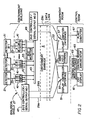
- the overall architecture of the rod position indicating system is illustrated in Figure 2.
- one level of redundancy is used except that only one detector 21 and one set of interconnecting leads 25 are provided for each drive rod.
- Field history has shown these components to be sufficiently reliable to be used without backup in most applications.
- the system architecture is also applicable to systems using redundant detector coils.
- the signals on leads 25 from each of the detectors 21 are applied to a separate encoder card 41 housed in the data cabinet 23 in the containment building.
- Each of the detector cards 41 has two identical circuits, labeled A and B in Figure 2, which process the signals generated by the detector coils to produce redundant binary gray code representations of rod position.
- a key aspect of the invention is that the redundant information from the A and B circuits on the encoder cards 41 is distributed to each set of redundant components in the system.
- the encoder cards 41 include four separate fault isolating bus interfaces which feed the redundant binary rod position signals generated by the A and B circuits to each of two redundant, fully independent, byte parallel communications buses 43 and 45 physically provided on backplane cards in the data cabinet 23.
- Each of the communications buses 41 and 43 is controlled by a bus controller/serial output device 47 and 49 respectively mounted on its own printed circuit card in cabinet 23.
- Each bus controller/serial output card polls each redundant half of each encoder card 41 to collect and store all of the rod position data once per second.
- These devices also contain circuitry to monitor the local environment including temperature, power supply voltage, door "open" status, and self test.
- Each of the bus controller/serial output cards 47 and 49 has two redundant individually buffered serial data link outputs 29a and b and 29c and d respectively.
- one bus controller/serial output card, 47 for instance, one data link, 29a, is the primary link to a display controller/interface 51, which forms part of the equipment 31 located in the equipment room 33, and the second data link, 29b, serves as a backup input for a plant computer interface 53 also located in the equipment room.
- the other bus controller/serial output card, 49 has one data link, 29c, which is the primary link to the plant computer interface 53 and a second, 29d, which is a backup to the display controller/interface 51.
- the data stored by the bus controller/serial output cards 47 and 49 is formatted into three blocks for transmission over each of the associated pairs of data links.
- the three blocks contain, respectively, all rod positions from the "A" portion of each of the encoder cards, all rod positions from the "B" portion of each of the encoder cards, and a fixed field and system status information.
- the data is transmitted using an asynchronous simplex byte count oriented protocol similar to DDCMP (digital data communications message protocol).
- DDCMP digital data communications message protocol.
- the bus controller/serial output cards 47 and 49 each utilize a single chip microprocessor for control of all functions. As a result, the sequence of bus control and serial data link protocol can be easily modified for unique applications.
- a single bus monitor card 55 is provided to improve self test and fault diagnosis.
- the bus controller/serial output cards, 47 and 49 When polled by the bus controller/serial output cards, 47 and 49, it provides complementary fixed binary codes in place of rod position signals. Proper receipt of those codes verifies the integrity of each bus and assists in the isolation of system faults to the board level before maintenance personnel enter the containment building.
- separate bus monitor cards can be provided at the remote end of each bus 43 and 45 to assure continuity of the entire bus.
- the fixed field block of data transmitted by each bus controller/serial output device provides a means for checking and isolating faults in the data links 29.
- the containment electronics in data cabinet 23 also includes fully redundant d-c power supplies that are individually distributed via the backplane and are diode auctioneered at the board level.
- the display controller/interface 51 and the plant computer interface 53 which comprise the controller/ interface equipment 31 located in the equipment room 33, each receive data from the two bus controller/serial output cards 47 and 49 over serial data links 29a and d and 29c and b respectively. Only one serial data link is used by either subsystem at any given time. The source of the data is chosen manually by a toggle switch 57.
- Each subsystem 51, 53 receives the serially transmitted data and checks for transmission errors. They also check system status failures and compare the rod position data from the redundant portions of each encoder card 41 as a reasonability check.
- Only one source, either "A" or "B", of data for each rod is used for control of display, alarm and plant computer interfaces.
- the selection of the set of redundant data to be used is made manually by a small hand-held portable terminal 59 which may be plugged as needed into the display controller/interface 51 or plant computer interface 53.
- the operator may choose that all rod position data be taken from the "A" side or the "B" side of each encoder card 41 or he may choose which side the data will be taken from on a rod by rod basis.
- the instructions are stored in non-volatile memory so that the system will automatically return to the previous operating mode following a power outage.
- the ability to manually select the source of the data both from the bus controller/serial output cards and from the encoder cards, as well as the overall system architecture, insures maximum fault tolerance and recoverability for those few equipment failures that may occur.
- Each subsystem 51 and 53 processes its set of rod position data and controls its associated display devices.
- the display controller interface 51 formats the data for one of five display pages and produces an output compatible for driving a color cathode ray tube (CRT) monitor 61 in the main control board located in the control room 39.
- the operator interface is provided with four push buttons 63 also in the main control board to control system reset, alarm acknowledgement, rod position data page selection and system alarm page selection.
- the display controller interface 51 also provides two contact closure outputs to a control board annunciator system 65 for urgent and non-urgent alarms.
- the urgent alarm results from any of the many detectable system failures.
- Those system alarms are displayed on the CRT 61.
- the non-urgent alarms result from detectable misplacement of rods including rod deviation (rod to rod in a bank), rod on bottom, and rod off top. These alarms are also displayed on the CRT 61 as more fully described below.
- the plant computer interface 53 generates outputs suitable for use by the plant computer 67 located in the control room for generating on its CRT, displays similar to those presented on the CRT color monitor 61 thus providing the redundant representation of the rod positions.
- the plant computer also logs the rod position signals for record keeping purposes.
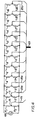
- Figures 3 and 4 illustrate a suitable rod position detector 21 for use with the invention.
- the detector depicted is the digital detector covered by commonly owned copending application Serial No. 675,423 filed on October 3, 1984.
- the drive rod 13 is longitudinally movable inside the tubular housing 19 and is preferably made of a material of high magnetic permeability such as steel, but could also be made of an electrically conductive material in which eddy currents can be induced by magnetic fields.
- Spaced along the travel path of the drive rod 13 at spaced intervals along the outside of the housing 19 are a number of electrical coils L 1 through L 20'
- each of the coils L 1 through L 20 is energized by a low voltage, low frequency, for instance 12 volt 60 hertz, a-c power source.
- the magnetic fields generated by such a low frequency current in the coils penetrate the non-magnetic housing 19 and, where it is present, the drive rod 13. Since the drive rod is electrically conductive and/or preferably magnetically permeable, the impedance of each coil in succession changes as the end of the drive rod passes through it. Thus, by monitoring the sequential changes in the impedance of the coils, the movement of the rod can be tracked.
- Pairs of the detector coils are connected in series across the a-c source 69 together with a pair of series connected resistors R 1 and R 2 which are located in the data cabinet 23.
- Leads 25a through 25j connect the common nodes 71 of each resistor pair with appropriate circuits on dedicated encoder card 41 in the data cabinet 23.
- Lead 73 connects the common node 75 between the resistors R 1 and R 2 with these same circuits which compare the voltage at node 75 with that at each of the nodes 71 of the coil pairs.
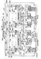
- Figure 5 illustrates the circuits on one of the encoder boards 41 which processes the signals from one of the detectors 21.
- the leads 25a through j from the detector coils are applied to the input side of a printed circuit board 77 through connector 79.
- Each of the leads 25a through 25j is split at a branch point 81 into two leads 25a' and a" through 25j' and j" with each of the leads 25a' through 25j' applied to one input of a differential amplifier 83A in a processing circuit 85A through an input resistor 87A, and with each of the leads 25a" through 25j" applied through an input resistor 87B to one input of a differential amplifier 83B in processing circuit 85B.
- the signals from one set would be applied to the differential amplifiers 83A and those from the other set to the amplifiers 85B.
- the lead 73 from the common node 75 between the resistors R 1 and R 2 which are physically located on the printed circuit board 77, is applied to the other input of each of the differential amplifiers 83A and B through resistors 87A and B respectively.
- the differential a-c voltages produced by the amplifiers 83A and B are applied to discriminators 91A and B respectively where they are converted to d-c signals and compared with threshold levels to generate standard logic outputs, DO through D 9 .
- the 10 digit binary signals produced by the discriminators 91A and B are converted to 8 bit signals, D 0 ' through D 7 ', in converters 93A and B respectively to be compatible with the 8 bit structure of the downstream components even though 5 digits would be sufficient to identify the location of the rod with respect to the 20 coils.
- the 8 bit binary signals D O ' through D 7 ' produced by the processing circuits 85A and B are each applied through an interface 95 to each of the communications buses, BUS No. 1, 43, and BUS No. 2, 45.
- the leads 97a through 97h carrying the 8 bit signal from the A processing circuit are split into two leads each 97a' through h' and 97a" through h" for application to an A Data Bus Drive 99' and 99" associated with the No. 1 and No. 2 Buses 43 and 45 respectively.
- the 8 bit signal from the converter 93B in the B processing circuit is applied over leads 101a through h which split into lOla' through lOlh' and 101" through h" to B Data Bus Drivers 103' and 103".
- Each of the bus drivers 99', 99", 103' and 103" includes 8 CMOS gates 105 which selectively feed either the applied A or B data to each of the 8 bit buses 43 and 45 through leads 107 and 109 and connectors 111 and 113 respectively.
- a Bus 1 Address Decoder 115 receives a detector address signal DET ADD, and A/B DATA signal and an ENABLE signal from the BUS 1 through connector 111. These signals are generated by the bus controller/serial output No. 1, 47, to control the sequential transmission of data on communications Bus No. 1..
- the DET ADD signal identifies which board (i.e.
- the A/B DATA signal determines which of the redundant sets of signals, A or B, is to be transmitted and the ENABLE signal implements the transfer.
- the ENABLE signal applies a pulse to each of the CMOS gates 105 in A Data Bus Driver 99' through lead 117 to apply the 8 bit digital position signal generated by processing circuit 85A to Bus No. 1.
- an ENABLE signal applies a pulse through lead 119 to each of the CMOS gates (not shown) in B Data Bus Driver 103'.
- the A data and B data are applied to BUS No. 2 by similar control signals generated by bus controller/serial output No. 2, 49, and applied to BUS 2 Address Decoder 121 which responds by pulsing the A Data Bus Driver 99" through lead 123 and the B Data Bus Driver 103" through lead 125 as commanded.
- the input impedance of the differential amplifiers 83A and B and the value of the input resistors 87A and B and 89A and B is very high while the impedance of the coils L 1 to L 20 and resistors R 1 and R 2 is low so that a failure in one of the processing circuits 85A or B is not propagated to the other through the inputs.
- the input impedance of the CMOS gates 105 in the bus drivers 99', 99", 103' and 103" is very high as is the value of resistors 127', 127", 129' and 129" while the output impedance of the converters 93A and B is relatively low so that no faults are propagated through the outputs.
- the serial transmission of data through the communications buses, and data links as well as the digital storage of data in the bus controller/serial outputs preserve the isolation of the redundant detector signals.
- the primary function of the rod position indicating system is to provide plant operators with as much information as possible concerning the position of the rods in the reactor core. It was determined that this could best be done by presenting the information to the operator in the form of graphical displays on a color CRT rather than through individual analog or digital indicators. Redundant displays are made available by presenting the rod position information on the CRT of the plant computer 67 as well as the dedicated CRT 61 in the control room.
- FIG. 1 illustrates the control rod display page 131A.
- the major field of the CRT is devoted to a bargraph representation 133 of rod position, while space is reserved at the bottom of each page for status messages 135. This arrangement provides the operator with information pertinent to abnormal conditions on the other pages while viewing the position data on a particular page.
- Rod position is displayed by bank.
- the customary convention of indicating rod position by the number of steps the rod has been withdrawn is utilized with a scale of 1 to 228 steps in 12 step increments shown.
- the amount of withdrawal is shown on the bargraph in a prominent color such as yellow with the background shown in a less prominent color such as blue.
- the identification of the rod and the number of steps it is withdrawn is shown below the bar.
- ERR appears in reverse video with a red background and no bar is shown as for the rod H10 in the A bank of control rods.
- the average value of the valid rod position signals is shown after the bank label, for instance "152" for the B bank.
- the second status message is identified as the "Rod on Bottom” signal.
- the boron system is used to accommodate long term changes in load so that this condition prevails.
- all the shutdown rods should be fully withdrawn.
- all of the rods should be "on the bottom” or fully inserted.
- this message alerts the operator to an abnormal condition during operation and provides a quick reference during a reactor trip whether all the rods have been fully inserted.
- Figure 6 it can be seen that all of the rods in the D bank, except one which is out of place, are on the bottom indicating an abnormal condition in the control system which should be investigated.
- the third status message is "Rod Off Top" which is only pertinent as to the shutdown rods and indicates in Figure 6 that rods in the A and C shutdown banks are not fully withdrawn as they should be with the reactor at power. If the operator wants more detailed information, he can page to the shutdown rod page which is presented in the simpler format to Figure 6 to see in more detail from the bargraphs what the situation is.
- the part-length rod page for plants having such rods is much similar since there is only one bank of such rods and normally they are fully withdrawn under present control schemes.
- the fourth status message is the rod position indicating system alarm message "RPI System Alarm".
- "See Alarm Page” message appears in reverse video, the operator should look to the remaining two pages which include the "System Status" page 131B of Figure 7.
- This page shows the status of system components by location.
- PROM and RAM memory check results are displayed. The valid check results are shown in blue while components which failed the test are shown in red.
- the number 2 PROM memory and number 6 RAM have failed their tests and are thus shown in red which also generates a "System Alarm" in the lower right-hand corner of this page and the "See Alarm Page” signal on the rod position pages.
- the "Number Of Main Loop Time-outs" count shown for the equipment room electronics is the number of times the dead man timer timed out since the last software reset. This number provides a measure of system integrity.
- the “Containment Electronics” section indicates the status of components in the cabinet 23 located inside the containment building. The items displayed are self- explanatory.
- the “Communication System” section provides information on the status of the data link which is supplying data to the redundant display being viewed. "The quick brown fox jumped over the lazy dog” is an example of the fixed field header message which is transmitted as an integrity check.
- the "Header Count” indicates how many times this message has been received correctly and the A and B counts indicate the number of times the A and B data have been received without an error. A system alarm is generated if any of the three counts exceeds the average of the counts.
- a maintenance page can also be provided which displays the raw data received on each rod and can be referred to for more detailed information in case of a system alarm.
Landscapes
- Physics & Mathematics (AREA)
- Engineering & Computer Science (AREA)
- Plasma & Fusion (AREA)
- General Engineering & Computer Science (AREA)
- High Energy & Nuclear Physics (AREA)
- Monitoring And Testing Of Nuclear Reactors (AREA)
- Arrangements For Transmission Of Measured Signals (AREA)
- Small-Scale Networks (AREA)
- Selective Calling Equipment (AREA)
Applications Claiming Priority (2)
| Application Number | Priority Date | Filing Date | Title |
|---|---|---|---|
| US06/665,228 US4668465A (en) | 1984-10-26 | 1984-10-26 | Method and apparatus for remotely monitoring a process carried out in a containment structure |
| US665228 | 1984-10-26 |
Publications (3)
| Publication Number | Publication Date |
|---|---|
| EP0179341A2 true EP0179341A2 (de) | 1986-04-30 |
| EP0179341A3 EP0179341A3 (en) | 1987-12-16 |
| EP0179341B1 EP0179341B1 (de) | 1991-01-02 |
Family
ID=24669258
Family Applications (1)
| Application Number | Title | Priority Date | Filing Date |
|---|---|---|---|
| EP85112635A Expired - Lifetime EP0179341B1 (de) | 1984-10-26 | 1985-10-04 | Verfahren und Einrichtung zur Abstandskontrolle eines in einer Behälterstruktur bewerkstelligten Prozesses |
Country Status (8)
| Country | Link |
|---|---|
| US (1) | US4668465A (de) |
| EP (1) | EP0179341B1 (de) |
| JP (1) | JPS61105940A (de) |
| KR (1) | KR930010418B1 (de) |
| CN (1) | CN1008567B (de) |
| CA (1) | CA1227583A (de) |
| DE (1) | DE3581046D1 (de) |
| ES (1) | ES8707368A1 (de) |
Cited By (1)
| Publication number | Priority date | Publication date | Assignee | Title |
|---|---|---|---|---|
| DE10159081B4 (de) | 2001-11-26 | 2018-08-02 | Volkswagen Ag | Verfahren und Vorrichtung zur Übertragung von redundanten Informationen |
Families Citing this family (27)
| Publication number | Priority date | Publication date | Assignee | Title |
|---|---|---|---|---|
| US4770842A (en) * | 1986-11-20 | 1988-09-13 | Westinghouse Electric Corp. | Common bus multinode sensor system |
| US4818994A (en) * | 1987-10-22 | 1989-04-04 | Rosemount Inc. | Transmitter with internal serial bus |
| US5068080A (en) * | 1989-02-07 | 1991-11-26 | Westinghouse Electric Corp. | Operation state responsive automatic display selection system |
| US5006301A (en) * | 1989-03-22 | 1991-04-09 | Joyner Engineers And Trainers, Inc. | Method and apparatus for control rod drop monitoring |
| US4964462A (en) * | 1989-08-09 | 1990-10-23 | Smith Michael L | Tubing collar position sensing apparatus, and associated methods, for use with a snubbing unit |
| US5014781A (en) * | 1989-08-09 | 1991-05-14 | Smith Michael L | Tubing collar position sensing apparatus, and associated methods, for use with a snubbing unit |
| US5373308A (en) * | 1989-11-03 | 1994-12-13 | Zilog, Inc. | Color bargraph display control for use with a cathode ray tube |
| DE3939295A1 (de) * | 1989-11-28 | 1991-05-29 | Rheinmetall Gmbh | Verfahren und vorrichtung zur herstellung von grosskalibriger munition |
| US5263061A (en) * | 1992-06-24 | 1993-11-16 | Westinghouse Electric Corp. | Nuclear reactor control room construction |
| AU5012593A (en) * | 1992-08-11 | 1994-03-15 | Brooks Support Systems, Inc. | A transportable receiving and display device for imaging a defined environment |
| US5694039A (en) * | 1996-03-07 | 1997-12-02 | Honeywell Inc. | Angular position sensor having multiple magnetic circuits |
| EP1018122B1 (de) * | 1997-01-15 | 2005-03-09 | Westinghouse Electric Company LLC | Datenerfassungssystem für steuerstabantrieb |
| RU2150756C1 (ru) * | 1999-01-28 | 2000-06-10 | Грибов Алексей Алексеевич | Способ сбора и обработки сигналов в системе контроля активной зоны ядерного реактора и система для его осуществления |
| US6404835B1 (en) * | 2000-03-22 | 2002-06-11 | Analysis & Measurement Services Corporation | Nuclear reactor rod drop time testing method |
| FR2807866B1 (fr) * | 2000-04-14 | 2002-07-19 | Framatome Sa | Dispositif de mesure du temps de chute de barres de commande a l'interieur du coeur d'un reacteur nucleaire |
| US6954819B2 (en) * | 2002-01-09 | 2005-10-11 | Storcase Technology, Inc. | Peripheral bus switch to maintain continuous peripheral bus interconnect system operation |
| US6918068B2 (en) * | 2002-04-08 | 2005-07-12 | Harris Corporation | Fault-tolerant communications system and associated methods |
| US8351561B2 (en) * | 2008-01-09 | 2013-01-08 | Analysis And Measurement Services Corporation | Advanced digital control rod position indication system with rod drop monitoring for nuclear power plants |
| FR2932310B1 (fr) * | 2008-06-10 | 2010-08-13 | Areva Np | Procede et dispositif de surveillance a distance de vannes manuelles de circuits fluides dans l'ilot nucleaire d'une centrale nucleaire |
| US9431137B2 (en) * | 2011-06-14 | 2016-08-30 | Analysis And Measurement Services Corporation | Systems and methods of monitoring control rods of a nuclear power plant |
| JP6614991B2 (ja) | 2016-02-09 | 2019-12-04 | 三菱重工業株式会社 | フローダンパおよび蓄圧注水装置ならびに原子力設備 |
| JP6650776B2 (ja) | 2016-02-09 | 2020-02-19 | 三菱重工業株式会社 | フローダンパおよび蓄圧注水装置ならびに原子力設備 |
| US10910115B2 (en) * | 2017-03-08 | 2021-02-02 | Ge-Hitachi Nuclear Energy Americas Llc | Digital systems and methods for high precision control in nuclear reactors |
| CN107833643B (zh) * | 2017-10-16 | 2019-05-24 | 中核核电运行管理有限公司 | 全数字化棒位测量装置及其方法 |
| US11862350B2 (en) * | 2021-01-22 | 2024-01-02 | Westinghouse Electric Company Llc | Nuclear movable element position indication apparatus, system, and method |
| RU2759182C1 (ru) * | 2021-03-11 | 2021-11-10 | Российская Федерация, от имени которой выступает Государственная корпорация по атомной энергии "Росатом" (Госкорпорация "Росатом") | Автоматизированная система контроля физических параметров исследовательской ядерной установки |
| CN114188051B (zh) * | 2021-12-03 | 2024-02-20 | 中国原子能科学研究院 | 监测安全棒的位置的方法及装置 |
Family Cites Families (11)
| Publication number | Priority date | Publication date | Assignee | Title |
|---|---|---|---|---|
| US3852661A (en) * | 1971-01-27 | 1974-12-03 | Westinghouse Electric Corp | A position indicator employing magnetic circuits to monitor the position of a magnetically permeable member movable along an axis having one degree of freedom |
| US3855059A (en) * | 1972-05-11 | 1974-12-17 | M Groves | Hydraulic system for nuclear reactors with hydraulically driven control rods |
| JPS5612078B2 (de) * | 1972-11-30 | 1981-03-18 | ||
| US3858191A (en) * | 1973-01-03 | 1974-12-31 | Westinghouse Electric Corp | Digital multiplexed position indication and transmission system |
| US3846771A (en) * | 1973-01-03 | 1974-11-05 | Westinghouse Electric Corp | Position indication system |
| US3893090A (en) * | 1973-01-03 | 1975-07-01 | Westinghouse Electric Corp | Position indication system |
| US4170754A (en) * | 1975-10-16 | 1979-10-09 | Westinghouse Electric Corp. | Phase encoded digital position probe assembly |
| US4125432A (en) * | 1977-01-24 | 1978-11-14 | Combustion Engineering, Inc. | Drive mechanism nuclear reactor control rod |
| JPS56103556A (en) * | 1980-01-23 | 1981-08-18 | Hitachi Ltd | Duplication switching system for remote monitor device |
| US4385028A (en) * | 1980-03-20 | 1983-05-24 | Lord Electric Company, Inc. | System for controlling position and movement of manipulator device from absolute distance data standard |
| US4371496A (en) * | 1980-06-18 | 1983-02-01 | Westinghouse Electric Corp. | Position indication system |
-
1984
- 1984-10-26 US US06/665,228 patent/US4668465A/en not_active Expired - Fee Related
-
1985
- 1985-06-21 CA CA000484813A patent/CA1227583A/en not_active Expired
- 1985-10-04 DE DE8585112635T patent/DE3581046D1/de not_active Expired - Lifetime
- 1985-10-04 EP EP85112635A patent/EP0179341B1/de not_active Expired - Lifetime
- 1985-10-24 ES ES548198A patent/ES8707368A1/es not_active Expired
- 1985-10-25 JP JP60237752A patent/JPS61105940A/ja active Pending
- 1985-10-25 CN CN85109177A patent/CN1008567B/zh not_active Expired
- 1985-10-26 KR KR1019850007940A patent/KR930010418B1/ko not_active Expired - Lifetime
Cited By (1)
| Publication number | Priority date | Publication date | Assignee | Title |
|---|---|---|---|---|
| DE10159081B4 (de) | 2001-11-26 | 2018-08-02 | Volkswagen Ag | Verfahren und Vorrichtung zur Übertragung von redundanten Informationen |
Also Published As
| Publication number | Publication date |
|---|---|
| KR860003618A (ko) | 1986-05-28 |
| ES8707368A1 (es) | 1987-07-16 |
| CN1008567B (zh) | 1990-06-27 |
| KR930010418B1 (ko) | 1993-10-23 |
| EP0179341B1 (de) | 1991-01-02 |
| ES548198A0 (es) | 1987-07-16 |
| US4668465A (en) | 1987-05-26 |
| JPS61105940A (ja) | 1986-05-24 |
| CA1227583A (en) | 1987-09-29 |
| CN85109177A (zh) | 1986-09-03 |
| EP0179341A3 (en) | 1987-12-16 |
| DE3581046D1 (de) | 1991-02-07 |
Similar Documents
| Publication | Publication Date | Title |
|---|---|---|
| EP0179341B1 (de) | Verfahren und Einrichtung zur Abstandskontrolle eines in einer Behälterstruktur bewerkstelligten Prozesses | |
| US6049578A (en) | Digital plant protection system | |
| US4957690A (en) | System and method for monitoring and control of safety-related components of a nuclear power plant | |
| US3919533A (en) | Electrical fault indicator | |
| DE3410803A1 (de) | Datenuebertragungssystem zum uebertragen aneinandergereihter seismikdaten | |
| US6292523B1 (en) | Digital engineered safety features actuation system | |
| US3893090A (en) | Position indication system | |
| EP1324350B1 (de) | Vorrichtung und Verfahren zur Kontrole der Bewegung eines Kontrolstabs eines Nuklear Reaktors | |
| WO1998056008A1 (en) | Digital engineered safety features actuation system | |
| US3855590A (en) | Cyclic or monitoring system for displaying the output of two substantially similar trains of logic | |
| JPS6233638B2 (de) | ||
| KR100496126B1 (ko) | 제어봉구동장치 제어계통 코일전류 감시시스템 및 방법 | |
| US3895351A (en) | Automatic programming system for standardizing multiplex transmission systems | |
| Neuner et al. | An Advanced Digital ROD Postion Indication System for Pressurized Water Reactors | |
| JP3050928B2 (ja) | 制御棒位置監視装置 | |
| Dufek et al. | A Fault Tolerant Multiplexed Control Rod Position Detection and Indication System for Nuclear Power Plants | |
| Battle et al. | Remote control system for a 2-MW research reactor | |
| CA3206056A1 (en) | Nuclear movable element position indication apparatus, system, and method | |
| Karim et al. | Renovation of PARR instrumentation and controls | |
| Bradley | Safety Assessment Methods for New AGR Fuel Route Control Systems | |
| Bhattacharya | Influence of design improvements in optimising staffing of NPPs-an Indian experience | |
| Authority | WATTS BAR NUCLEAR PLANT (WBN)-LICENSE AMENDMENT (WBN-TS-03-12) MONITORING OF CONTROL OR SHUTDOWN ROD POSITION BY AN ALTERNATE MEANS | |
| Lupton et al. | Expert systems use in present and future CANDU nuclear power supply systems | |
| Ekamn | Saturation margin and core exit temperature monitoring system of Loviisa nuclear power plant | |
| Basu | Fermi 2 emergency response information system |
Legal Events
| Date | Code | Title | Description |
|---|---|---|---|
| PUAI | Public reference made under article 153(3) epc to a published international application that has entered the european phase |
Free format text: ORIGINAL CODE: 0009012 |
|
| AK | Designated contracting states |
Kind code of ref document: A2 Designated state(s): BE CH DE FR GB IT LI SE |
|
| PUAL | Search report despatched |
Free format text: ORIGINAL CODE: 0009013 |
|
| AK | Designated contracting states |
Kind code of ref document: A3 Designated state(s): BE CH DE FR GB IT LI SE |
|
| 17P | Request for examination filed |
Effective date: 19880419 |
|
| 17Q | First examination report despatched |
Effective date: 19900202 |
|
| ITF | It: translation for a ep patent filed | ||
| GRAA | (expected) grant |
Free format text: ORIGINAL CODE: 0009210 |
|
| AK | Designated contracting states |
Kind code of ref document: B1 Designated state(s): BE CH DE FR GB IT LI SE |
|
| ET | Fr: translation filed | ||
| PGFP | Annual fee paid to national office [announced via postgrant information from national office to epo] |
Ref country code: DE Payment date: 19910206 Year of fee payment: 7 |
|
| REF | Corresponds to: |
Ref document number: 3581046 Country of ref document: DE Date of ref document: 19910207 |
|
| PGFP | Annual fee paid to national office [announced via postgrant information from national office to epo] |
Ref country code: CH Payment date: 19910822 Year of fee payment: 7 |
|
| PGFP | Annual fee paid to national office [announced via postgrant information from national office to epo] |
Ref country code: BE Payment date: 19911024 Year of fee payment: 7 |
|
| PGFP | Annual fee paid to national office [announced via postgrant information from national office to epo] |
Ref country code: SE Payment date: 19911030 Year of fee payment: 7 |
|
| PLBE | No opposition filed within time limit |
Free format text: ORIGINAL CODE: 0009261 |
|
| STAA | Information on the status of an ep patent application or granted ep patent |
Free format text: STATUS: NO OPPOSITION FILED WITHIN TIME LIMIT |
|
| 26N | No opposition filed | ||
| PGFP | Annual fee paid to national office [announced via postgrant information from national office to epo] |
Ref country code: FR Payment date: 19920921 Year of fee payment: 8 |
|
| PG25 | Lapsed in a contracting state [announced via postgrant information from national office to epo] |
Ref country code: SE Effective date: 19921005 |
|
| PG25 | Lapsed in a contracting state [announced via postgrant information from national office to epo] |
Ref country code: LI Effective date: 19921031 Ref country code: CH Effective date: 19921031 Ref country code: BE Effective date: 19921031 |
|
| BERE | Be: lapsed |
Owner name: WESTINGHOUSE ELECTRIC CORP. Effective date: 19921031 |
|
| REG | Reference to a national code |
Ref country code: CH Ref legal event code: PL |
|
| PG25 | Lapsed in a contracting state [announced via postgrant information from national office to epo] |
Ref country code: DE Effective date: 19930701 |
|
| PG25 | Lapsed in a contracting state [announced via postgrant information from national office to epo] |
Ref country code: FR Effective date: 19940630 |
|
| REG | Reference to a national code |
Ref country code: FR Ref legal event code: ST |
|
| EUG | Se: european patent has lapsed |
Ref document number: 85112635.9 Effective date: 19930510 |
|
| PGFP | Annual fee paid to national office [announced via postgrant information from national office to epo] |
Ref country code: GB Payment date: 19961003 Year of fee payment: 12 |
|
| PG25 | Lapsed in a contracting state [announced via postgrant information from national office to epo] |
Ref country code: GB Free format text: LAPSE BECAUSE OF NON-PAYMENT OF DUE FEES Effective date: 19971004 |
|
| GBPC | Gb: european patent ceased through non-payment of renewal fee |
Effective date: 19971004 |