EP0178263B1 - Gas laser having at least one excitation region with an axial gas flow - Google Patents
Gas laser having at least one excitation region with an axial gas flow Download PDFInfo
- Publication number
- EP0178263B1 EP0178263B1 EP85810460A EP85810460A EP0178263B1 EP 0178263 B1 EP0178263 B1 EP 0178263B1 EP 85810460 A EP85810460 A EP 85810460A EP 85810460 A EP85810460 A EP 85810460A EP 0178263 B1 EP0178263 B1 EP 0178263B1
- Authority
- EP
- European Patent Office
- Prior art keywords
- arrangement
- gas
- tube
- laser according
- gas laser
- Prior art date
- Legal status (The legal status is an assumption and is not a legal conclusion. Google has not performed a legal analysis and makes no representation as to the accuracy of the status listed.)
- Expired - Lifetime
Links
Images


Classifications
-
- H—ELECTRICITY
- H01—ELECTRIC ELEMENTS
- H01S—DEVICES USING THE PROCESS OF LIGHT AMPLIFICATION BY STIMULATED EMISSION OF RADIATION [LASER] TO AMPLIFY OR GENERATE LIGHT; DEVICES USING STIMULATED EMISSION OF ELECTROMAGNETIC RADIATION IN WAVE RANGES OTHER THAN OPTICAL
- H01S3/00—Lasers, i.e. devices using stimulated emission of electromagnetic radiation in the infrared, visible or ultraviolet wave range
- H01S3/09—Processes or apparatus for excitation, e.g. pumping
- H01S3/097—Processes or apparatus for excitation, e.g. pumping by gas discharge of a gas laser
- H01S3/0979—Gas dynamic lasers, i.e. with expansion of the laser gas medium to supersonic flow speeds
-
- H—ELECTRICITY
- H01—ELECTRIC ELEMENTS
- H01S—DEVICES USING THE PROCESS OF LIGHT AMPLIFICATION BY STIMULATED EMISSION OF RADIATION [LASER] TO AMPLIFY OR GENERATE LIGHT; DEVICES USING STIMULATED EMISSION OF ELECTROMAGNETIC RADIATION IN WAVE RANGES OTHER THAN OPTICAL
- H01S3/00—Lasers, i.e. devices using stimulated emission of electromagnetic radiation in the infrared, visible or ultraviolet wave range
- H01S3/02—Constructional details
- H01S3/03—Constructional details of gas laser discharge tubes
- H01S3/036—Means for obtaining or maintaining the desired gas pressure within the tube, e.g. by gettering, replenishing; Means for circulating the gas, e.g. for equalising the pressure within the tube
-
- H—ELECTRICITY
- H01—ELECTRIC ELEMENTS
- H01S—DEVICES USING THE PROCESS OF LIGHT AMPLIFICATION BY STIMULATED EMISSION OF RADIATION [LASER] TO AMPLIFY OR GENERATE LIGHT; DEVICES USING STIMULATED EMISSION OF ELECTROMAGNETIC RADIATION IN WAVE RANGES OTHER THAN OPTICAL
- H01S3/00—Lasers, i.e. devices using stimulated emission of electromagnetic radiation in the infrared, visible or ultraviolet wave range
- H01S3/02—Constructional details
- H01S3/03—Constructional details of gas laser discharge tubes
- H01S3/038—Electrodes, e.g. special shape, configuration or composition
-
- H—ELECTRICITY
- H01—ELECTRIC ELEMENTS
- H01S—DEVICES USING THE PROCESS OF LIGHT AMPLIFICATION BY STIMULATED EMISSION OF RADIATION [LASER] TO AMPLIFY OR GENERATE LIGHT; DEVICES USING STIMULATED EMISSION OF ELECTROMAGNETIC RADIATION IN WAVE RANGES OTHER THAN OPTICAL
- H01S3/00—Lasers, i.e. devices using stimulated emission of electromagnetic radiation in the infrared, visible or ultraviolet wave range
- H01S3/05—Construction or shape of optical resonators; Accommodation of active medium therein; Shape of active medium
- H01S3/06—Construction or shape of active medium
- H01S3/07—Construction or shape of active medium consisting of a plurality of parts, e.g. segments
- H01S3/073—Gas lasers comprising separate discharge sections in one cavity, e.g. hybrid lasers
Abstract
Description
Die vorliegende Erfindung betrifft einen Gaslaser mit mindestens einem axial gasdurchströmten Erregungsrohr, sowie mit einer Elektrodenanordnung zur elektrischen Erregung des Gases im Rohr, sowie mit einer an der Peripherie des Erregungsrohres im wesentlichen gleich verteilt einmündenden Einlassanordnung und einer usmündenden Auslassanordnung für das Gas, wobei die Einlassanordnung in Axialschnitten betrachtet, eine äussere, gegen die Wandung des Erregungsrohres konvergierende Strömungsführung aufweist.The present invention relates to a gas laser with at least one excitation tube through which gas flows axially, and with an electrode arrangement for the electrical excitation of the gas in the tube, and with an inlet arrangement which opens at the periphery of the excitation tube and has an outlet arrangement for the gas which is essentially uniformly distributed, the inlet arrangement viewed in axial sections, has an outer flow guide converging against the wall of the excitation tube.
Ein Gaslaser der genannten Art ist aus der EP-A-0080715 bekannt. Die Einlassanordnung umfasst eine koaxial, zum Erregungsrohr angeordnete Verteilkammer, deren Aussenwandung sich in einer Stufe auf den Durchmesser des Erregungsrohres verringert. Als äussere Strömungsführung für das Gas aus der Verteilkammer ist diese Stufe durch einen hohlkegelförmigen Füllkörper mit geraden Mantellinien ausgeglichen. Innen ist die Verteilkammer durch einen im wesentlichen, dem Durchmesser des Entladungsrohres angepassten Rohrstutzen, begrenzt, wobei axial zwischen diesem Rohrstutzen und dem Erregungsrohr ein aussen durch den erwähnten Hohlkegelkörper begrenzter Raum gebildet wird. In diesen Raum strömt im wesentlichen axial das Gas aus der Verteilkammer ein und durchströmt in diesem Raum im wesentlichen in Querschnittsebene liegend Elektrodenplatten mit koaxial angeordneten Kränzen von Gasdurchtrittsöffnungen.A gas laser of the type mentioned is known from EP-A-0080715. The inlet arrangement comprises a distribution chamber arranged coaxially to the excitation tube, the outer wall of which is reduced in one step to the diameter of the excitation tube. As an external flow guide for the gas from the distribution chamber, this stage is balanced by a hollow-cone-shaped filler body with straight surface lines. The inside of the distribution chamber is delimited by a pipe socket which is essentially matched to the diameter of the discharge tube, a space delimited axially between this pipe socket and the excitation tube by the hollow cone body mentioned. The gas from the distribution chamber flows essentially axially into this space and flows through electrode plates in this space, lying essentially in the cross-sectional plane, with coaxially arranged rings of gas passage openings.
Nun ist es bekannt, dass bei Axialgaslasern die Entstehung grossräumiger Turbulenzen im Erregungsrohr möglichst verhindert werden muss. Die Turbulenzverhältnisse entlang des Erregungsrohres sind, unter anderem auch massgeblich durch die Verhältnisse an der Einlassanordnung zum Erregungsrohr, bestimmt.It is now known that the occurrence of large-scale turbulence in the excitation tube must be prevented as far as possible with axial gas lasers. The turbulence conditions along the excitation tube are, among other things, also largely determined by the conditions at the inlet arrangement to the excitation tube.
Im folgenden gilt die Definition:
- Eine Turbulenz in einem Erregungsrohr ist "grossräumig", falls über den Rohrquerschnitten ein Turbulenzzentrum vorliegt. Liegen zwei oder mehrere solcher Zentren vor, wird die Turbulenz als "kleinräumig" bezeichnet.
- Turbulence in an excitation tube is "large-scale" if there is a turbulence center above the tube cross-sections. If there are two or more such centers, the turbulence is referred to as "small-scale".
Die erwähnt grossräumigen Turbulenzen werden nun insbesondere dadurch erzeugt, dass bei der irgendwo zwangsläufig radial zugeführten Gasströmung, dank deren Umlenkung in axiale Richtung im Entladungsrohr an der Peripherie des Erregungsrohres unterschiedlich kleinräumige Turbulenzen bzw. Wirbel entstehen, so dass durch eine solche, bezüglich der Erregungsrohrachse asymmetrische Anregung im Strom abliegenden Erregungsrohr die erwähnt grossräumigen Turbulenzen entstehen.The above-mentioned large-scale turbulence is now generated in particular by the fact that in the gas flow that is inevitably radially supplied somewhere, thanks to its deflection in the axial direction in the discharge tube at the periphery of the excitation tube, turbulences or vortices of different sizes arise, so that such asymmetry with respect to the excitation tube axis Excitation in the excitation tube located in the current, the large-scale turbulences mentioned arise.
Die vorliegende Erfindung setzt sich zum Ziel an einem Gaslaser genannter Art zu verhindern, dass entlang des Erregungsrohres grossräumige Turbulenzen entstehen. Zu diesem Zweck zeichnet sich die Erfindung nach dem Wortlaut des kennzeichnenden Teils von Anspruch 1 aus.The present invention aims at a gas laser of the type mentioned to prevent large-scale turbulence from occurring along the excitation tube. For this purpose, the invention is characterized by the wording of the characterizing part of
Dadurch, dass die äussere Strömungsführung erfindungsgemäss stetig gebogen und stetig in die Rohrwandung übergeführt ist, im wesentlichen ohne dass an Kanten Turbulenzen gebildet werden, wird die Gaszuführung, ohne Quellen kleinräumiger Wirbel, die zu grossräumigen Turbulenzen Anlass geben, vorgenommen.Due to the fact that the outer flow guide is continuously bent and continuously transferred into the tube wall, essentially without turbulence being formed at the edges, the gas is supplied without swelling of small-area vortices that give rise to large-scale turbulence.
Ausführungsvarianten der Erfindung sowie allenfalls zusätzlich vorzusehende Massnahmen zur weiteren Verbesserung der Turbulenzverhältnisse entlang des Erregungsstreckenrohres werden nachfolgend anhand von Figuren beispielsweise erläutert.Embodiment variants of the invention and any additional measures to be provided to further improve the turbulence conditions along the excitation section tube are explained below with reference to figures, for example.
Es zeigen:
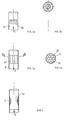
- Fig. 1 eine prinzipielle Darstellung eines "zweistufigen" Hochleistungsgaslasers,
- Fig. 2a schematisch einen Abschnitt eines Gaseinlassrohres, mit Mitteln zur Verhinderung grossräumiger Turbulenz,
- Fig. 2b.eine Querschnittdarstellung der Anordnung gemäss Fig. 2a mit qualitativ eingetragenen zu erreichenden kleinräumigen Turbulenzen,
- Fig. 3a eine Darstellung analog zu Fig. 2a, mit einer weiteren Variante der Mittel,
- Fig. 3b eine schematische Schnittdarstellung gemäss Linie III-III durch die Anordnung von Fig. 3a,
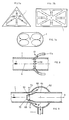
- Fig. 4 eine Darstellung analog zu den Fig. 2a und 3a mit einer weiteren Ausführungsvariante der Grossturbulenz-verhindernden Mittel,
- Fig. 5a eine schematische Querschnittsdarstellung durch einen erfindungsgemässen Einlasszonenbereich einer Erregungsstrecke,
- Fig. 5b eine schematische Längsschnittdarstellung durch den erfindungsgemässen Bereich von Fig. 5a,
- Fig. 6 einen Längsschnittabschnitt analog zur Darstellung von Fig. 5b einer bevorzugten Realisationsform des erfindungsgemässen Einlassbereiches,
- Fig. 7a - c schematische Querschnittsdarstellungen durch eine Erregungsstrecke zur Verhinderung grossräumiger Turbulenzen,
- Fig. 8 eine schematische Längsschnittdarstellung durch eine erfindungsgemässe Gasauslasszone,
- Fig. 9 eine Darstellung analog zu Fig. 8 in einer weiteren Ausführungsvariante,
- Fig. 10 anhand einer Darstellung, analog zu den Fig. 8 und 9, eine weitere Ausführungsvariante der erfindungsgemässen Auslasszone,
- Fig. 11 eine Erweiterung der Anordnung gemäss Fig. 10 für einen "zweistufigen" Laser gemäss Fig. 1,
- Fig. 12 eine schematische Darstellung einer weiteren Ausführungsvariante einer erfindungsgemässen Auslasszone,
- Fig. 13 eine schematische Querschnittsdarstellung durch eine Erregungsstrecke mit Einzel-Elektroden,
- Fig. 14 eine schematische Längsschnittdarstellung einer Laser-Erregungsstrecke, mit anoden-und kathodenseitig, gemäss Fig. 13 ausgebildeten Elektroden sowie einer Feldbild-Steuereinheit,
- Fig. 15 anhand eines Erregungstrecken-Längsschnittabschnittes eine weitere Elektrodenvariante,
- Fig. 16 anhand einer Darstellung analog zu Fig. 15 eine weitere Variante der dort dargestellten Elektrode.
- 1 is a basic representation of a "two-stage" high-power gas laser,
- 2a schematically shows a section of a gas inlet pipe with means for preventing large-scale turbulence,
- 2b shows a cross-sectional view of the arrangement according to FIG. 2a with small-scale turbulence to be achieved,
- 3a shows a representation analogous to FIG. 2a, with a further variant of the means,
- 3b is a schematic sectional view along line III-III through the arrangement of Fig. 3a,
- 4 shows a representation analogous to FIGS. 2a and 3a with a further embodiment variant of the means preventing large turbulence,
- 5a shows a schematic cross-sectional view through an inlet zone region according to the invention of an excitation section,
- 5b is a schematic longitudinal sectional view through the area according to the invention from FIG. 5a,
- 6 shows a longitudinal section analogous to the illustration in FIG. 5b of a preferred embodiment of the inlet area according to the invention,
- 7a-c are schematic cross-sectional representations through an excitation section to prevent large-scale turbulence,
- 8 shows a schematic longitudinal section through a gas outlet zone according to the invention,
- 9 shows a representation analogous to FIG. 8 in a further embodiment variant,
- 10 with the aid of a representation, analogous to FIGS. 8 and 9, a further embodiment variant of the outlet zone according to the invention,
- 11 shows an extension of the arrangement according to FIG. 10 for a “two-stage” laser according to FIG. 1,
- 12 shows a schematic illustration of a further embodiment variant of an outlet zone according to the invention,
- 13 shows a schematic cross-sectional illustration through an excitation section with individual electrodes,
- 14 is a schematic longitudinal sectional view of a laser excitation path, with electrodes formed on the anode and cathode side, according to FIG. 13, and a field image control unit,
- 15 on the basis of an excitation path length section another electrode variant,
- FIG. 16 shows a further variant of the electrode shown there on the basis of a representation analogous to FIG. 15.
In Fig. 1 ist prinzipiell die Anordnung eines bekannten Hochleistungsgaslasers dargestellt. Es handelt sich dabei um einen "Zweistufen"-Laser, mit einer ersten Stufe links der strichpunktierten Markierung und einer zweiten Stufe rechts davon. Da es sich mit Bezug auf diese Markierung um spiegelbildlich angeordnete, identische Stufen handelt, wird lediglich die Stufe links beschrieben. Die Anordnung umfasst ein Erregungsstrekkenrohr 1, an deren Enden Kathode 3 und Anode 5 angeordnet sind. Am einen Ende des Erregungsstreckenrohres 1 mündet, an einer Einlasszone 7, ein Einlassrohr 9 in das Erregungsstrekkenrohr 1 ein, am anderen Ende mündet ein Auslassrohr 11 aus einer Aulasszone 13 des Erregungsstreckenrohres 1 aus. Mit Hilfe eines Gebläses 15, welchem Wärmetauscher 17 und 19 vor- bzw. nachgeschaltet sind, wird ein Gasgemisch, wie z.B. aus Kohlendioxid, Stickstoff, und Wassefstoff durch das Erregungsstreckenrohr 1 in der mit dem Pfeil angegebenen Richtung getrieben. Die Zentralachse A des beidseitig offenen Erregungsstreckenrohres ist gleichzeitig die optische Achse des Laserstrahles. Wie weiter dargestellt, werden die Elektroden 3 und 5 über eine Hochspannungsquelle 21, ein Stellglied 23, beispielsweise in Form einer Röhre, betrieben, wobei mit Hilfe der Röhre 23 und einer sie ansteuernden Stromregulierung 25 der Elektrodenstrom eingestellt wird.In Fig. 1 the arrangement of a known high power gas laser is shown in principle. It is a "two-stage" laser, with a first stage to the left of the dot-dash line and a second stage to the right. Since the levels are mirror-inverted, identical levels are described, only the level on the left is described. The arrangement comprises an
Die vorliegende Erfindung bezieht sich nun u.a. auf Massnahmen an der Einlasszone 7, und auf Massnahmen an der Auslasszone 13, sowie auf die Ausbildung von Kathode und/oder Anode, alles Massnahmen, die aerodynamisch und/oder elektrisch grossräumige Turbulenzen im Erregungsstreckenrohr 1 verhindern, dabei dort eine gute Gasdurchmischung sicherstellen sollen.The present invention now relates inter alia to on measures at the
Anhand der Fig. 2 bis 16 werden Massnahmen zur Verhinderung grossräumiger Erregungsstrekkenrohrturbulenzen beschrieben, wobei die wesentlichsten in Fig. 5a bis 6, 8 bis 12 dargestellt und diesbezüglich beschrieben werden.2 to 16, measures for preventing large-area excitation tube turbulence are described, the most important of which are shown in FIGS. 5a to 6, 8 to 12 and described in this regard.
In den Fig. 2 bis 4 ist ein Abschnitt des einlasszonenseitigen Einlassrohres 9 für das Gasgemisch G dargestellt. Im Bereich der Einlasszone 7 wird gemäss Fig. 2a im Einlassrohr 9 ein oder allenfalls mehrere Gitter 28 angeordnet, wie dargestellt vorzugsweise in Querschnittsebene. Dadurch wird eine kleinräumige Turbulenz bereits im Rohr 9 erzeugt, wie in Fig. 2b schematisch dargestellt.2 to 4, a section of the
Grossräumige Turbulenzen im Rohr 9, wie in Fig. 2b strichpunktiert eingetragen, die sich in die Strecke fortpflanzen könnten, werden dadurch weitgehendst unterbunden. In Fig. 3a ist anstelle des Gitters 28 eine Mehrzahl von Wänden 30 im Einlassrohr 9 angeodnnet, die den Strömungsquerschnitt unterteilen.Large-scale turbulence in the
Wie in Fig. 3b dargestellt, werden diese Wände 30 vorzugsweise so angeordnet, dass sie ein Honigwabenmuster 32 bilden. Auch durch diese Massnahme wird der angestrebte Effekt erreicht.As shown in FIG. 3b, these
In Fig. 4 ist eine weitere derartige Massnahme dargestellt. Hier ist am Einlassrohr 9 eine kontinuierliche Einschnürung 34 angeformt, in Gasströmungsrichtung betrachtet, somit erst eine kontinuierliche Leitungswandkonvergenz, dann -divergenz eingebaut. Auch durch diese Massnahme wird der erwähnte Zweck erreicht. Die Massnahmen gemäss den Fig. 2 bis 4 können, falls erforderlich, einzeln oder allenfalls in Kombination mit den anhand der Figuren 5 - 6 noch zu beschreibenden wesentlichen Massnahmen eingesetzt werden.Another measure of this type is shown in FIG. Here, a
Im wesentlichsten wird nun einlasszonenseitig ein Entstehen grossräumiger Turbulenzen durch die in den Fig. 5 und 6 dargestellten Massnahmen verhindert. In Fig. '5a ist prinzipiell die hierzu vorgeschlagene Technik dargestellt. Am Umfang des Erregungsstreckenrohres 1 kontinuierlich oder, wie in Fig. 5a und 5b dargestellt, diskontinuierlich verteilt, sind Gaseinlassöffnungen 42 angeordnet, die mit einem Satz Einlassrohren 9a verbunden sind, und die das Gas stetig von mehr radialer Richtung in mehr axiale, bezüglich der Strecke 1 leiten, die entlang des Streckenumfanges gleich verteilt sind.Essentially, large-scale turbulence is prevented on the inlet zone side by the measures shown in FIGS. 5 and 6. The technique proposed for this purpose is shown in principle in FIG. 5a. 5a and 5b, discontinuously distributed,
Wie in Fig. 5b dargestellt, wird dabei vorzugsweise die Ausrichtung der Einlassöffnungen 42 so gewählt, dass die Gaseinströmung mindestens vornehmlich in Richtung der Achse A stetig ohne an Kanten Turbulenzen zu bilden in das Erregungsstreckenrohr 1 erfolgt.As shown in FIG. 5 b, the orientation of the
Um nun weiter sicherzustellen, dass ab einer für alle Einlassöffnungen 42 bzw. Einlassrohre 9a gemeinsamen Druckgasspeisung, alle vorgesehenen Einlassöffnungen 42 gleichermassen beaufschlagt werden, werden, wie in Fig. 5a schematisch eingetragen, alle Einlassrohre 9a in eine gemeinsame Ausgleichskammer 44 geführt, welch letztere durch eine Gaszuspeiseleitung 46 gespiesen wird. Dadurch wird am Umfang des Erregungsstreckenrohres 1 überall eine gleichmässige, vornehmlich achsial gerichtete Gaseinströmung sichergestellt. Die anhand der Fig. 2 - 4 beschriebenen Massnahmen können allenfalls an den Rohren 9a vorgesehen werden.In order to further ensure that, starting from a compressed gas supply common to all
In Fig. 6 ist eine bevorzugte Ausführungsform der Einlasszone dargestellt. Das Erregungsstrekkenrohr 1 ist einlasszonenseitig zu einem Wulst 48 ausgeformt. Zusammen mit einem die Fortsetzung des Erregungsstreckenrohres 1 bildenden Rohrabschnitt 50 gleichen Innendurchmessers wie der einlasszonenseitige Abschnitt des Erregungsstreckenrohres 1, wird eine Ausgleichskammer 44a als Ringkammer um die Achse A gebildet, in die mindestens ein Einlassrohr 9 einmündet. Der Auslass aus der Ringausgleichskammer 44a erfolgt zwischen einem dem Erregungsstrekkenrohr zugekehrten Ende des Abschnittes 50 und der Anfangspartie des Wulstes 48, wodurch eine sich stetig verengende Ringspaltdüse 52 gebildet wird. Auf diese Art und Weise wird eine optimal gleichmässige, vornehmlich mit Bezug auf das Erregungsstreckenrohr achsial gerichtete Gaseinströmung in besagtes Rohr 1 erzielt.6 shows a preferred embodiment of the inlet zone. The
Wie in der Figur dargestellt, können alternativ oder additiv auf der Innenseite des Rohrabschnittes 50 oder der Aussenseite, d.h. der der Ringausgleichskammer 44a zugekehrten Seite, entlang des Rohrabschnittumfanges, Ringelektroden 54i bzw. 54a vorgesehen werden. Die weitere Möglichkeit, die Wandung des Rohrabschnittes 50 direkt als Elektrode einzusetzen, ist nicht eingezeichnet. Die grundsätzlich ringförmig ausgebildete Elektrode kann, wie noch zu beschreiben sein wird, aus einzelnen, am Umfang verteilten Elektrodenabschnitten bestehen, die unter sich isoliert sind. Vorzugsweise weisen die erwähnten Elektrodenabschnitte oder auch bevorzugterweise eingesetzte durchgehende Elektrodenringe gegen das Erregungsstreckenrohr 1 gerichtete scharfe Unstetigkeitsstellen auf, wie Spitzen 56, zur Erzeugung von lokal sehr hohen Feldstärken.As shown in the figure, alternatively or additively, on the inside of the
In den Fig. 7a bis 7c sind nun Massnahmen dargestellt, die allenfalls zur weiteren Verbesserung der Turbulenzverhältnisse am Erregungsstreckenrohr selbst eingesetzt werden können.In FIGS. 7a to 7c, measures are now shown that can at best be used to further improve the turbulence conditions on the excitation section tube itself.
Bekannterweise ist die Tendenz, dass sich in einem Rohr über dessen Strömungsquerschnitt einzeln und damit im obgenannten Sinn grossvoluminös Turbulenzen ergeben, deste höher, je genauer der Rohrquerschnitt kreisförmig ist. Da dies zu verhindern gerade Zweck der vorgeschlagenen Massnahmen ist, wird gemäss den Fig. 7a - c der Strömungsquerschnitt des Erregungsstrekkenrohres 1 von einer Kreisform abweichend ausgebildet, beispielsweise dreieckförmig, vierekkig, mehreckig oder elliptisch.As is known, the tendency that individual and therefore large-volume turbulence occurs in a pipe across its flow cross-section is higher, the more precisely the pipe cross-section is circular. Since this is precisely to prevent the proposed measures, the flow cross-section of the
In den Fig. 7 sind die dadurch entstehenden symmetrischen kleinvoluminösen Turbulenzen qualitativ eingetragen. Diese fördern eine gute Durchmischung des achsial das Erregungsstrekkenrohr 1 durchströmenden Gases.7, the resulting symmetrical small-volume turbulence is entered qualitatively. These promote good mixing of the gas flowing axially through the
Die Fig. 8 bis 12 zeigen nun wesentliche Massnahmen bzw. den Einsatz von entsprechenden Mitteln an der Auslasszone 13 des Erregungsstreckenrohres 1. Zur Sicherstellung eines, was grossvoluminöse Turbulenz anbetrifft, rückwirkungsfreien Gasauslasses an der Auslasszone 13 wird gemäss Fig. 8, in Analogie zu den Vorkehrungen einlasszonenseitig gemäss Fig. 5b, am Umfang des Erregungsstreckenrohres 1 erfindungswesentlich ein kontinuierlicher, oder wie in Fig. 8 mit den Oeffnungen 58 dargestellt, diskontinuierlich stetiger Auslass gebildet. Gemäss Fig. 8 sind verteilt am Umfang des Rohres 1 Auslassöffnungen 58 vorgesehen, die alle stetig mit Auslassrohren Ila kommunizieren, ihrerseits (nicht dargestellt) in eine Sammelkammer führend. Gemäss Fig. 9 ist kontinuierlich am Umfang des Rohres 1 ein sich stetig aufweitender Ringauslasssschlitz 60 gebildet, indem das Rohr 1 zu einem Wulst 62 ausgeformt ist, und auf der dem Rohr 1 abgekehrten Seite des Wulstes 62, ein Rohrabschnitt 64 derart in den Wulst einragt, dass einerseits eine Sammelkammer 66 als Ringkammer um die Achse A gebildet wird, anderseits der ringförmige Auslassschlitz 60. Die Sammelkammer 66 kommuniziert mit dem Auslassrohr 11. Auch hier wird weiter vorgeschlagen, im Bereich des Auslassschlitzes 60 eine Elektrode, wie eine Kathode 68 als Ringkathode, mit Unstetigkeitsstellen 70, vorzusehen, mit entsprechendem elektrischen Anschluss 72.8 to 12 now show essential measures or the use of corresponding means at the
In der Ausführungsform gemässs Fig. 10, wiederum mit wulstgebildeter Ringkammer 66, werden durch hintereinander achsial gestaffelte Ringlamellen 74 mehrere stetig die Gasflussrichtung umrichtende Ringauslassschlitze 60a, 60b... gebildet. Auch bei dieser Ausführungsform können die Ringlamellen für den Einsatz als Elektrode, wie als Kathode, mit elektrischen Anschlüssen 72 versehen sein.In the embodiment according to FIG. 10, again with a bead-shaped
Fig. 11 zeigt schematisch die Ausbildung der Auslasszone 13, analog zu Fig. 10 für einen zweistufigen Laser, wie er in Fig. 1 dargestellt ist.FIG. 11 schematically shows the design of the
In Fig. 12 ist eine Anordnung grundsätzlich analog zu derjenigen in Fig. 11 dargestellt, d.h. für einen zweistufigen Laser. Anstelle von ringförmig umlaufenden Lamellen sind ein oder mehrere Schaufelkränze 76 vorgesehen. Zur Unerstützung der Gaseinströmung in das Auslassrohr 11 kann nun insbesondere an den Ausführungsvarianten gemäss den Fig. 10 bis 12, wie dies in Fig. 12 dargestellt ist, zusätzlich eine Hochdruckgasleitung 78 in die Sammelkammer 66 einmünden, vorzugsweise mit einer Mündung, die koaxial zur Mündung der Leitung 9 ist. Durch diese Hochdruckgasleitung 78 wird ein Gasstrahl G2 durch die Kammer 66 geblasen und unterstützt im Sinne einer Vektoraddition der Gasstrahlimpulse das Absaugen der aus dem Erregungsstreckenrohr 1 zuströmenden Gase G.FIG. 12 shows an arrangement basically analogous to that in FIG. 11, ie for a two-stage laser. Instead of annular lamellae, one or more blade rings 76 are provided. In order to support the gas inflow into the
In den Fig. 13 und 14 ist eine Elektrodenanordnung, bestehend aus Kathode und/oder Anode, dargestellt, die bezweckt, den verfolgten Zweck allenfalls in Kombination mit einen oder mehreren der bis anhin beschriebenen Massnahmen, elektrisch zu erzielen bzw. zu unterstützen. Hierzu wird bzw. werden Anode 80 und/oder Kathode 82 grundsätzlich als Ringelektrode ausgebildet. Der Ring ist jedoch, wie besonders aus Fig. 13 ersichtlich, nicht durchgehend als Elektrode eingesetzt, sondern weist achsial ausgerichtete Einzelelektroden in Form von Elektrodenstiften 84 auf.In Figs. 13 and 14 an electrode assembly consisting, is shown from the cathode and / or anode which is intended to ver f olgten purpose possibly in combination with one or more of, to achieve electrically hitherto described measures or support. For this purpose,
Diese Elektrodenstifte 84 sind isoliert voneinander montiert und weisen je einen elektrischen Anschluss 86 auf. Gemäss der Figur sind die Elektrodenstifte 84 der Anode 80 mit Anschlüssen 86a, diejenigen der Kathode 82 mit Anschlüssen 86k verbunden und je auf entsprechende Eingänge E einer Steuereinheit 88 geführt. Der Steuereinheit 88 wird ein Zeittaktsignal von einem Generator 90 zugeführt sowie die Spannung der Hochspannungsquelle 38. Die Steuereinheit 88 wirkt nun als Multiplexereinheit mit Multiplexerschaltern Sa und Sk und schaltet, wählbar, gleichzeitig ein oder mehrere anodenseitige Elektrodenstifte 84 und einen oder mehrere kathodenseitige Stifte 82 gleichzeitig auf die Spannungsquelle 38 auf. Werden somit beispielsweise anoden- und kathodenseitig je ein Elektrodenstift aufgeschaltet, so wird das Feldbild entlang der Erregungsstrecke 1 durch die Winkellage der gleichzeitig aufgeschalteten Stifte mit Bezug auf die Achse A festgelegt. Es kann somit, wie angedeutet, ein elektrisches Wirbelfeld erzeugt werden, mit dessen Hilfe auch die Gasturbulenz im Erregungsstreckenrohr beeinflusst werden kann.These electrode pins 84 are mounted insulated from one another and each have an electrical connection 86. According to the figure, the electrode pins 84 of the
In den Fig. 15 und 16 sind nun weitere Elektrodenanordnungen für den Anoden- und/oder Kathodeneinsatz dargestellt. Zwischen dem Erregungsstreckenrohr 1 und dessen Fortsetzung la für den Laserstrahl in der Achse A wird die jeweilige Elektrode gemäss Fig. 15 als Zylinderelektrode 92 ausgelegt. Dabei wird sie so dimensioniert, dass sie wenigstens nahezu absatzfrei die Innenwandungen der Rohre 1 bzw. la verbindet. Sie stützt sich, beispielsweise auf beidseitig angeordneten, achsial ausgerichteten Ringkragen 94 ab. Müssen nach dem Erregungsstreckenrohr 1 die Querschnittsdimensionen des Fortsetzungsrohres la mit Bezug auf die Querschnittsdimensionen des Erregungsstreckenrohres 1 geändert werden, so wird, wie in Fig. 16 dargestellt, die Elektrode 96 entsprechend divergierend oder konvergierend ausgebildet, wobei sichergestellt bleibt, dass die Innenwandungen der Rohre 1 und la einerseits praktisch absatzfrei verbunden werden, und radial praktisch spaltfrei, dank eines dünnen Innenkragens 94i.15 and 16 further electrode arrangements for anode and / or cathode use are now shown. Between the
Claims (19)
Priority Applications (1)
| Application Number | Priority Date | Filing Date | Title |
|---|---|---|---|
| AT85810460T ATE55659T1 (en) | 1984-10-10 | 1985-10-08 | GAS LASER WITH AT LEAST ONE AXIAL GAS-FLOW EXCITATION SECTION. |
Applications Claiming Priority (2)
| Application Number | Priority Date | Filing Date | Title |
|---|---|---|---|
| CH4861/84 | 1984-10-10 | ||
| CH486184 | 1984-10-10 |
Publications (2)
| Publication Number | Publication Date |
|---|---|
| EP0178263A1 EP0178263A1 (en) | 1986-04-16 |
| EP0178263B1 true EP0178263B1 (en) | 1990-08-16 |
Family
ID=4283835
Family Applications (2)
| Application Number | Title | Priority Date | Filing Date |
|---|---|---|---|
| EP85810460A Expired - Lifetime EP0178263B1 (en) | 1984-10-10 | 1985-10-08 | Gas laser having at least one excitation region with an axial gas flow |
| EP85810459A Expired EP0178262B1 (en) | 1984-10-10 | 1985-10-08 | Method for increasing the output of an axial gas laser, and axial gas laser using this method |
Family Applications After (1)
| Application Number | Title | Priority Date | Filing Date |
|---|---|---|---|
| EP85810459A Expired EP0178262B1 (en) | 1984-10-10 | 1985-10-08 | Method for increasing the output of an axial gas laser, and axial gas laser using this method |
Country Status (8)
| Country | Link |
|---|---|
| US (3) | US4692928A (en) |
| EP (2) | EP0178263B1 (en) |
| JP (3) | JPH0693526B2 (en) |
| AT (2) | ATE55659T1 (en) |
| AU (2) | AU580108B2 (en) |
| CA (2) | CA1268533A (en) |
| DE (2) | DE3573200D1 (en) |
| WO (2) | WO1986002498A1 (en) |
Cited By (1)
| Publication number | Priority date | Publication date | Assignee | Title |
|---|---|---|---|---|
| DE10050603B4 (en) * | 1999-10-12 | 2006-04-20 | Matsushita Electric Industrial Co., Ltd., Kadoma | Laser oscillator device |
Families Citing this family (9)
| Publication number | Priority date | Publication date | Assignee | Title |
|---|---|---|---|---|
| DE3573200D1 (en) * | 1984-10-10 | 1989-10-26 | Prc Corp | Method for increasing the output of an axial gas laser, and axial gas laser using this method |
| JPH08270335A (en) * | 1995-03-29 | 1996-10-15 | Yamaji Fudosan Kk | Door member and its manufacture |
| EP0922888B1 (en) * | 1997-12-10 | 2003-05-21 | Festo AG & Co | Sealing ring |
| EP1248332B1 (en) | 2000-05-30 | 2004-05-12 | Matsushita Electric Industrial Co., Ltd. | Laser oscillating device |
| US6931046B1 (en) * | 2000-09-14 | 2005-08-16 | The Regents Of The University Of California | High power laser having a trivalent liquid host |
| JP4489557B2 (en) * | 2004-10-21 | 2010-06-23 | 黒田精工株式会社 | Ball screw lubrication seal device |
| JP4137961B2 (en) * | 2006-07-13 | 2008-08-20 | ファナック株式会社 | Gas laser oscillator |
| EP2712036A1 (en) * | 2012-09-24 | 2014-03-26 | Excico France | A gas circulation loop for a laser gas discharge tube |
| JP5927218B2 (en) * | 2014-03-12 | 2016-06-01 | ファナック株式会社 | Laser oscillator including discharge tube, and laser processing apparatus |
Citations (1)
| Publication number | Priority date | Publication date | Assignee | Title |
|---|---|---|---|---|
| US3671883A (en) * | 1969-10-20 | 1972-06-20 | Aga Ab | Process and apparatus for effecting high gas flow in discharge tube of gas laser |
Family Cites Families (17)
| Publication number | Priority date | Publication date | Assignee | Title |
|---|---|---|---|---|
| US3428914A (en) * | 1965-01-25 | 1969-02-18 | Spectra Physics | Gas lasers with plasma tube having variable cross-section and discharge current |
| US3720885A (en) * | 1971-04-30 | 1973-03-13 | Us Navy | Transverse flow carbon dioxide laser system |
| JPS545958B2 (en) * | 1973-03-27 | 1979-03-23 | ||
| JPS5311072A (en) * | 1976-07-19 | 1978-02-01 | Nippon Telegr & Teleph Corp <Ntt> | Phase constant measuring method |
| JPS55121691A (en) * | 1979-03-14 | 1980-09-18 | Hitachi Ltd | Gas laser device |
| US4274065A (en) * | 1979-07-31 | 1981-06-16 | The United States Of America As Represented By The Secretary Of The Air Force | Closed cycle annular-return gas flow electrical discharge laser |
| JPS6022387B2 (en) * | 1980-10-06 | 1985-06-01 | カシオ計算機株式会社 | small electronic translator |
| JPS57188892A (en) * | 1981-05-18 | 1982-11-19 | Matsushita Electric Ind Co Ltd | Coaxial carbon dioxide laser oscillator |
| JPS5891690A (en) * | 1981-11-27 | 1983-05-31 | Hitachi Ltd | Generator for gas laser |
| US4457000A (en) * | 1982-03-03 | 1984-06-26 | Rockwell International Corporation | Shock wave suppressing flow plate for pulsed lasers |
| JPS58178579A (en) * | 1982-04-13 | 1983-10-19 | Matsushita Electric Ind Co Ltd | Laser oscillator |
| JPS58196080A (en) * | 1982-05-12 | 1983-11-15 | Toshiba Corp | Gas laser oscillating container |
| JPS597236A (en) * | 1982-07-06 | 1984-01-14 | Nissan Motor Co Ltd | Suction pressure sensor |
| JPS5956782A (en) * | 1982-09-25 | 1984-04-02 | Matsushita Electric Ind Co Ltd | Gas laser device |
| JPS59208890A (en) * | 1983-05-13 | 1984-11-27 | Nec Corp | High speed axial flow type gas laser tube |
| DE3323954A1 (en) * | 1983-07-02 | 1985-01-10 | Messer Griesheim Gmbh, 6000 Frankfurt | GAS LASER, IN PARTICULAR FAST-FLOWING AXIAL CURRENT GAS TRANSPORT LASER |
| DE3573200D1 (en) * | 1984-10-10 | 1989-10-26 | Prc Corp | Method for increasing the output of an axial gas laser, and axial gas laser using this method |
-
1985
- 1985-10-08 DE DE8585810459T patent/DE3573200D1/en not_active Expired
- 1985-10-08 JP JP60504318A patent/JPH0693526B2/en not_active Expired - Lifetime
- 1985-10-08 EP EP85810460A patent/EP0178263B1/en not_active Expired - Lifetime
- 1985-10-08 AT AT85810460T patent/ATE55659T1/en not_active IP Right Cessation
- 1985-10-08 AT AT85810459T patent/ATE46596T1/en not_active IP Right Cessation
- 1985-10-08 JP JP60504321A patent/JPH0714082B2/en not_active Expired - Lifetime
- 1985-10-08 AU AU49601/85A patent/AU580108B2/en not_active Ceased
- 1985-10-08 DE DE8585810460T patent/DE3579215D1/en not_active Expired - Lifetime
- 1985-10-08 WO PCT/CH1985/000149 patent/WO1986002498A1/en unknown
- 1985-10-08 WO PCT/CH1985/000150 patent/WO1986002499A1/en unknown
- 1985-10-08 EP EP85810459A patent/EP0178262B1/en not_active Expired
- 1985-10-08 AU AU49608/85A patent/AU584366B2/en not_active Ceased
- 1985-10-10 CA CA000492751A patent/CA1268533A/en not_active Expired - Lifetime
- 1985-10-10 US US06/786,058 patent/US4692928A/en not_active Expired - Fee Related
- 1985-10-10 US US06/786,052 patent/US4704719A/en not_active Ceased
- 1985-10-10 CA CA000492752A patent/CA1267715A/en not_active Expired - Lifetime
-
1989
- 1989-10-25 US US07/426,570 patent/USRE33803E/en not_active Expired - Lifetime
-
1994
- 1994-06-17 JP JP6136104A patent/JP2554024B2/en not_active Expired - Fee Related
Patent Citations (1)
| Publication number | Priority date | Publication date | Assignee | Title |
|---|---|---|---|---|
| US3671883A (en) * | 1969-10-20 | 1972-06-20 | Aga Ab | Process and apparatus for effecting high gas flow in discharge tube of gas laser |
Cited By (1)
| Publication number | Priority date | Publication date | Assignee | Title |
|---|---|---|---|---|
| DE10050603B4 (en) * | 1999-10-12 | 2006-04-20 | Matsushita Electric Industrial Co., Ltd., Kadoma | Laser oscillator device |
Also Published As
| Publication number | Publication date |
|---|---|
| JPH07142787A (en) | 1995-06-02 |
| JPH0714082B2 (en) | 1995-02-15 |
| DE3573200D1 (en) | 1989-10-26 |
| US4704719A (en) | 1987-11-03 |
| WO1986002498A1 (en) | 1986-04-24 |
| AU584366B2 (en) | 1989-05-25 |
| AU580108B2 (en) | 1989-01-05 |
| AU4960885A (en) | 1986-05-02 |
| ATE55659T1 (en) | 1990-09-15 |
| US4692928A (en) | 1987-09-08 |
| USRE33803E (en) | 1992-01-21 |
| ATE46596T1 (en) | 1989-10-15 |
| AU4960185A (en) | 1986-05-02 |
| JP2554024B2 (en) | 1996-11-13 |
| WO1986002499A1 (en) | 1986-04-24 |
| CA1268533A (en) | 1990-05-01 |
| EP0178262B1 (en) | 1989-09-20 |
| JPS62502155A (en) | 1987-08-20 |
| CA1267715A (en) | 1990-04-10 |
| DE3579215D1 (en) | 1990-09-20 |
| JPS62502437A (en) | 1987-09-17 |
| EP0178263A1 (en) | 1986-04-16 |
| JPH0693526B2 (en) | 1994-11-16 |
| EP0178262A1 (en) | 1986-04-16 |
Similar Documents
| Publication | Publication Date | Title |
|---|---|---|
| DE2164270A1 (en) | Plasma jet generator | |
| EP0171793B1 (en) | Plasma spray torch with cooled electrode and nozzle | |
| EP0075668B1 (en) | Compressed-gas circuit breaker | |
| EP0324043B1 (en) | Industrial burner using recuperative air preheating, especially for heating the chambers of industrial furnaces | |
| EP0178263B1 (en) | Gas laser having at least one excitation region with an axial gas flow | |
| DE3902825C2 (en) | Current arc engine | |
| WO1999001643A1 (en) | Turbine bucket wall section cooled by an impact flow | |
| DE102012100266A1 (en) | Curved cooling channels for a turbine component | |
| DE3522888A1 (en) | DEVICE FOR PRODUCING A PLASMA JET | |
| EP0017201B1 (en) | Direct current plasma torch | |
| DE4123153C2 (en) | Arc-beam thruster and anode body | |
| DE2933932A1 (en) | Steam generator with hydrogen and oxygen injection - has combustion chamber and water injection nozzles arranged to give even water distribution in chamber | |
| DE102015102311A1 (en) | Shell and tube heat exchanger | |
| EP1192333A1 (en) | Component that can be subjected to hot gas, especially a turbine blade | |
| EP1525646B1 (en) | Gas discharge laser | |
| DE1764978A1 (en) | Induction plasma generator | |
| AT524334B1 (en) | Ejector for a fuel cell system | |
| DE2844349C2 (en) | Post-combustion duct for a jet engine | |
| DD228338B1 (en) | COAL DUST BURNER | |
| CH665054A5 (en) | EXHAUST GAS SWITCH. | |
| DE3844141C1 (en) | ||
| DE2352650C3 (en) | Gas laser | |
| DE19537673C2 (en) | Laser arrangement, preferably high-power gas laser arrangement | |
| CH667348A5 (en) | Tuyere AT A GAS PRESSURE SWITCH. | |
| DE102022200045A1 (en) | Method for operating a fuel cell system, gas supply unit and fuel cell system with gas supply unit |
Legal Events
| Date | Code | Title | Description |
|---|---|---|---|
| PUAI | Public reference made under article 153(3) epc to a published international application that has entered the european phase |
Free format text: ORIGINAL CODE: 0009012 |
|
| AK | Designated contracting states |
Kind code of ref document: A1 Designated state(s): AT BE CH DE FR GB IT LI NL SE |
|
| RAP1 | Party data changed (applicant data changed or rights of an application transferred) |
Owner name: PRC CORPORATION |
|
| RIN1 | Information on inventor provided before grant (corrected) |
Inventor name: WEISS, HARDY P., DR. |
|
| 16A | New documents despatched to applicant after publication of the search report | ||
| 17P | Request for examination filed |
Effective date: 19861008 |
|
| 17Q | First examination report despatched |
Effective date: 19880128 |
|
| GRAA | (expected) grant |
Free format text: ORIGINAL CODE: 0009210 |
|
| AK | Designated contracting states |
Kind code of ref document: B1 Designated state(s): AT BE CH DE FR GB IT LI NL SE |
|
| REF | Corresponds to: |
Ref document number: 55659 Country of ref document: AT Date of ref document: 19900915 Kind code of ref document: T |
|
| ET | Fr: translation filed | ||
| GBT | Gb: translation of ep patent filed (gb section 77(6)(a)/1977) | ||
| ITF | It: translation for a ep patent filed |
Owner name: JACOBACCI & PERANI S.P.A. |
|
| REF | Corresponds to: |
Ref document number: 3579215 Country of ref document: DE Date of ref document: 19900920 |
|
| PLBE | No opposition filed within time limit |
Free format text: ORIGINAL CODE: 0009261 |
|
| STAA | Information on the status of an ep patent application or granted ep patent |
Free format text: STATUS: NO OPPOSITION FILED WITHIN TIME LIMIT |
|
| 26N | No opposition filed | ||
| ITTA | It: last paid annual fee | ||
| EAL | Se: european patent in force in sweden |
Ref document number: 85810460.7 |
|
| PGFP | Annual fee paid to national office [announced via postgrant information from national office to epo] |
Ref country code: SE Payment date: 19961010 Year of fee payment: 12 |
|
| PGFP | Annual fee paid to national office [announced via postgrant information from national office to epo] |
Ref country code: FR Payment date: 19961011 Year of fee payment: 12 |
|
| PGFP | Annual fee paid to national office [announced via postgrant information from national office to epo] |
Ref country code: NL Payment date: 19961029 Year of fee payment: 12 |
|
| PGFP | Annual fee paid to national office [announced via postgrant information from national office to epo] |
Ref country code: AT Payment date: 19961030 Year of fee payment: 12 |
|
| PGFP | Annual fee paid to national office [announced via postgrant information from national office to epo] |
Ref country code: BE Payment date: 19961031 Year of fee payment: 12 |
|
| PGFP | Annual fee paid to national office [announced via postgrant information from national office to epo] |
Ref country code: CH Payment date: 19961231 Year of fee payment: 12 |
|
| PG25 | Lapsed in a contracting state [announced via postgrant information from national office to epo] |
Ref country code: AT Free format text: LAPSE BECAUSE OF NON-PAYMENT OF DUE FEES Effective date: 19971008 |
|
| PG25 | Lapsed in a contracting state [announced via postgrant information from national office to epo] |
Ref country code: SE Free format text: LAPSE BECAUSE OF NON-PAYMENT OF DUE FEES Effective date: 19971009 |
|
| PG25 | Lapsed in a contracting state [announced via postgrant information from national office to epo] |
Ref country code: LI Free format text: LAPSE BECAUSE OF NON-PAYMENT OF DUE FEES Effective date: 19971031 Ref country code: FR Free format text: THE PATENT HAS BEEN ANNULLED BY A DECISION OF A NATIONAL AUTHORITY Effective date: 19971031 Ref country code: CH Free format text: LAPSE BECAUSE OF NON-PAYMENT OF DUE FEES Effective date: 19971031 Ref country code: BE Free format text: LAPSE BECAUSE OF NON-PAYMENT OF DUE FEES Effective date: 19971031 |
|
| BERE | Be: lapsed |
Owner name: PRC CORP. Effective date: 19971031 |
|
| PG25 | Lapsed in a contracting state [announced via postgrant information from national office to epo] |
Ref country code: NL Free format text: LAPSE BECAUSE OF NON-PAYMENT OF DUE FEES Effective date: 19980501 |
|
| REG | Reference to a national code |
Ref country code: CH Ref legal event code: PL |
|
| NLV4 | Nl: lapsed or anulled due to non-payment of the annual fee |
Effective date: 19980501 |
|
| EUG | Se: european patent has lapsed |
Ref document number: 85810460.7 |
|
| REG | Reference to a national code |
Ref country code: FR Ref legal event code: ST |
|
| REG | Reference to a national code |
Ref country code: GB Ref legal event code: IF02 |
|
| PGFP | Annual fee paid to national office [announced via postgrant information from national office to epo] |
Ref country code: DE Payment date: 20040930 Year of fee payment: 20 |
|
| PGFP | Annual fee paid to national office [announced via postgrant information from national office to epo] |
Ref country code: GB Payment date: 20041006 Year of fee payment: 20 |
|
| PG25 | Lapsed in a contracting state [announced via postgrant information from national office to epo] |
Ref country code: GB Free format text: LAPSE BECAUSE OF EXPIRATION OF PROTECTION Effective date: 20051007 |
|
| REG | Reference to a national code |
Ref country code: GB Ref legal event code: PE20 |