EP0178167A2 - Pick and place method and apparatus for handling electrical components - Google Patents
Pick and place method and apparatus for handling electrical components Download PDFInfo
- Publication number
- EP0178167A2 EP0178167A2 EP85307232A EP85307232A EP0178167A2 EP 0178167 A2 EP0178167 A2 EP 0178167A2 EP 85307232 A EP85307232 A EP 85307232A EP 85307232 A EP85307232 A EP 85307232A EP 0178167 A2 EP0178167 A2 EP 0178167A2
- Authority
- EP
- European Patent Office
- Prior art keywords
- component
- aligning
- longitudinal axis
- tips
- closing
- Prior art date
- Legal status (The legal status is an assumption and is not a legal conclusion. Google has not performed a legal analysis and makes no representation as to the accuracy of the status listed.)
- Withdrawn
Links
Images


Classifications
-
- H—ELECTRICITY
- H05—ELECTRIC TECHNIQUES NOT OTHERWISE PROVIDED FOR
- H05K—PRINTED CIRCUITS; CASINGS OR CONSTRUCTIONAL DETAILS OF ELECTRIC APPARATUS; MANUFACTURE OF ASSEMBLAGES OF ELECTRICAL COMPONENTS
- H05K13/00—Apparatus or processes specially adapted for manufacturing or adjusting assemblages of electric components
- H05K13/0015—Orientation; Alignment; Positioning
-
- H—ELECTRICITY
- H05—ELECTRIC TECHNIQUES NOT OTHERWISE PROVIDED FOR
- H05K—PRINTED CIRCUITS; CASINGS OR CONSTRUCTIONAL DETAILS OF ELECTRIC APPARATUS; MANUFACTURE OF ASSEMBLAGES OF ELECTRICAL COMPONENTS
- H05K13/00—Apparatus or processes specially adapted for manufacturing or adjusting assemblages of electric components
- H05K13/04—Mounting of components, e.g. of leadless components
- H05K13/0404—Pick-and-place heads or apparatus, e.g. with jaws
- H05K13/0413—Pick-and-place heads or apparatus, e.g. with jaws with orientation of the component while holding it; Drive mechanisms for gripping tools, e.g. lifting, lowering or turning of gripping tools
-
- H—ELECTRICITY
- H05—ELECTRIC TECHNIQUES NOT OTHERWISE PROVIDED FOR
- H05K—PRINTED CIRCUITS; CASINGS OR CONSTRUCTIONAL DETAILS OF ELECTRIC APPARATUS; MANUFACTURE OF ASSEMBLAGES OF ELECTRICAL COMPONENTS
- H05K13/00—Apparatus or processes specially adapted for manufacturing or adjusting assemblages of electric components
- H05K13/08—Monitoring manufacture of assemblages
- H05K13/081—Integration of optical monitoring devices in assembly lines; Processes using optical monitoring devices specially adapted for controlling devices or machines in assembly lines
- H05K13/0815—Controlling of component placement on the substrate during or after manufacturing
-
- Y—GENERAL TAGGING OF NEW TECHNOLOGICAL DEVELOPMENTS; GENERAL TAGGING OF CROSS-SECTIONAL TECHNOLOGIES SPANNING OVER SEVERAL SECTIONS OF THE IPC; TECHNICAL SUBJECTS COVERED BY FORMER USPC CROSS-REFERENCE ART COLLECTIONS [XRACs] AND DIGESTS
- Y10—TECHNICAL SUBJECTS COVERED BY FORMER USPC
- Y10T—TECHNICAL SUBJECTS COVERED BY FORMER US CLASSIFICATION
- Y10T29/00—Metal working
- Y10T29/49—Method of mechanical manufacture
- Y10T29/49002—Electrical device making
- Y10T29/49117—Conductor or circuit manufacturing
- Y10T29/49124—On flat or curved insulated base, e.g., printed circuit, etc.
- Y10T29/4913—Assembling to base an electrical component, e.g., capacitor, etc.
- Y10T29/49133—Assembling to base an electrical component, e.g., capacitor, etc. with component orienting
-
- Y—GENERAL TAGGING OF NEW TECHNOLOGICAL DEVELOPMENTS; GENERAL TAGGING OF CROSS-SECTIONAL TECHNOLOGIES SPANNING OVER SEVERAL SECTIONS OF THE IPC; TECHNICAL SUBJECTS COVERED BY FORMER USPC CROSS-REFERENCE ART COLLECTIONS [XRACs] AND DIGESTS
- Y10—TECHNICAL SUBJECTS COVERED BY FORMER USPC
- Y10T—TECHNICAL SUBJECTS COVERED BY FORMER US CLASSIFICATION
- Y10T29/00—Metal working
- Y10T29/53—Means to assemble or disassemble
- Y10T29/53022—Means to assemble or disassemble with means to test work or product
-
- Y—GENERAL TAGGING OF NEW TECHNOLOGICAL DEVELOPMENTS; GENERAL TAGGING OF CROSS-SECTIONAL TECHNOLOGIES SPANNING OVER SEVERAL SECTIONS OF THE IPC; TECHNICAL SUBJECTS COVERED BY FORMER USPC CROSS-REFERENCE ART COLLECTIONS [XRACs] AND DIGESTS
- Y10—TECHNICAL SUBJECTS COVERED BY FORMER USPC
- Y10T—TECHNICAL SUBJECTS COVERED BY FORMER US CLASSIFICATION
- Y10T29/00—Metal working
- Y10T29/53—Means to assemble or disassemble
- Y10T29/53039—Means to assemble or disassemble with control means energized in response to activator stimulated by condition sensor
- Y10T29/53061—Responsive to work or work-related machine element
-
- Y—GENERAL TAGGING OF NEW TECHNOLOGICAL DEVELOPMENTS; GENERAL TAGGING OF CROSS-SECTIONAL TECHNOLOGIES SPANNING OVER SEVERAL SECTIONS OF THE IPC; TECHNICAL SUBJECTS COVERED BY FORMER USPC CROSS-REFERENCE ART COLLECTIONS [XRACs] AND DIGESTS
- Y10—TECHNICAL SUBJECTS COVERED BY FORMER USPC
- Y10T—TECHNICAL SUBJECTS COVERED BY FORMER US CLASSIFICATION
- Y10T29/00—Metal working
- Y10T29/53—Means to assemble or disassemble
- Y10T29/5313—Means to assemble electrical device
- Y10T29/53174—Means to fasten electrical component to wiring board, base, or substrate
- Y10T29/53178—Chip component
Definitions
- the present invention relates to apparatus for the precision placement of electronic components on a hybrid circuit substrate and, more particularly, to the placement of small articles such as semiconductor chips, capacitor chips and integrated circuit chips on a ceramic substrate which has been preprinted with a thick film conductor pattern.
- hybrid circuits are a combination of discrete and integrated circuit techniques.
- conductors, resistors and conductive lands are printed on a ceramic substrate.
- the printed elements are generally several mils thick.
- discrete chips are precisely positioned over the conductive lands and subsequently bonded in position in a manner to complete the electrical circuit.
- the printed conductor lands provide a pattern which precisely matches to the corresponding conductive portions of the chips that connect to the circuit elements within the chip as by solder.
- the bonded chips and substrate, with.an exposed lead frame, are frequently encapsulated in toto in a potting compound for protection against physical and environmental damage.
- the small chips must be positioned and oriented such that when placed on the substrate, all solder connection portions and lands are properly connected without error. This requires a high degree of precision in positioning which was achieved in early development of these techniques by human operators using microscopes and tweezers.
- the need for automatic, rapid, precise, repeatable and low cost means to position and bond chips on substrates was apparent if the burgeoning requirements of mass production in the electronics industry were to be met.
- the chip or other small component e.g., beam leaded components
- the chip or other small component are picked up and placed by a hollow probe deyice which is connected to a vacuum source.
- the probe touches the upper flat surface of the chip, the . vacuum within the probe holds the chip against the probe end.
- the chip is then raided, translated to the substrate, and lowered onto the substrate.
- Prior attempts to improve the precision of placement of the components onto the circuit board have involved combining centering fingers with the vacuum probe.
- the fingers center the component relative thereto prior to placement.
- Permanent bonding of chip to substrate is accomplished in some systems while the probe continues to hold the chip.
- the conductive lands are pretreated with some form of tacky adhesive or soldering flux. The probe gently presses the chip surface into the tacky adhesive so that electrical contact is made with the conductive lands. Then the vacuum within the probe is released and the chip remains adhered to the substrate as the probe is withdrawn. A positive gas pressure within the probe is sometimes used to separate the chip from the probe.
- the substrate and the chip are both separately, fixedly and precisely oriented and located.
- a transfer mechanism usually utilizing a vacuum probe as described above, travels an invariable, repetitive path to pick up the chip and place it at one selected position on the substrate. Then, a new substrate and new chip are fed into their respective positions and the operation repeats.
- the chips start out with a degree of disorientation, for example, at random in a vibratory feeder bowl.
- the feeder bowl in the known manner, operates to bring each chip in turn to a precise position. From that point, the design is similar to the first category; although additional steps to angularly orient the. chip may be required intermediate the feeder bowl and the precisely located substrate. Still other prior art has combined these two categories.
- U.S. Patent No. 3,982,979 Another device for centering a chip on the vacuum probe prior to placement is disclosed in U.S. Patent No. 3,982,979.
- the rectangular component is supported from below on a probe using a slight vacuum.
- the probe is centered in a four-sided cavity having the form of an inverted truncated pyramid. As the probe is lowered, the component makes gontact with the cavity walls and becomes aligned thereto; at the same time, the component is centered on the probe.
- a substrate is precisely positioned above the cavity, and the probe is raised to position the centered component on the substrate from below.
- the apparatus should be capable at a single work station of placing a plurality of different chips of various types and physical and electrical sizes on a substrate with a high degree of precision as is required to complete the circuit. Precise location of stored chips should not be required; the apparatus should orient and center each chip after selection and prior to placement.
- the spindle using a vacuum, picks up components individually from a plurality of precisely fixed input stations, e.g., component trays, racks, feeder bowls, behind the machine and delivers them to varied locations on the substrate until the component placements have been completed.
- the substrate edges and the spindle housing provide X-Y reference points, and pivoted fingers attached to the spindle housing center the chip on the spindle while correcting for slight misorientations about the Z-axis i.e., less than 45°, prior to placement, so the chip need not be precisely positioned at the input station for selection.
- the support for the centering fingers is rotated about the vacuum probe axis, while the fingers are closed on the component, to provide control of the chip during angular orientation as the circuit board layout requires.
- a preferred embodiment of the invention also provides for rapid, automated changing of the tips of the centering fingers to accommodate components of varying sizes and configurations.
- each tip of a particular set of tips for the centering fingers may be provided with more than one area for engaging a component body so that; with a stepped component body engaging .portion of each tip, each tip can handle more than one component size or configuration according to the arrangement and location of the body engaging portion of the tip, and according to controlled stopping of the. vacuum probe in the "up" position, during which such centering takes place. Control of such an up-strdke stop position of the vacuum probe is facilitated by the provision of a programmable controller and a Z-axis servomotor.
- An advantage of the apparatus of the present invention is capability of selecting chip components successively from any of a plurality of component storage trays and placing them successively at various locations on a single substrate.
- a further advantage of the present invention is that the apparatus is flexible in operation and can readily operate with a new variety of components, new substrate patterns, and new programs and that it is precise in placement of components on a substrate.
- the apparatus allows imprecision in component storage and which squares and centers components prior to placement on a substrate.
- the apparatus may provide X-Y positioning and angular reorientation of components for placement on a substrate.
- the component may be reorientated about the Z-axis according to the.orientation needed for the proper placement of the component on the circuit board, and in which such orientation.is carried out while the component is vertically supported by the vacuum tube and clamped in the centering fingers during such reorientation,.and wherein the spindle housing is rotated with the vacuum tube to accomplish the reorientation.
- a further object of the present invention is an apparatus which senses and regulates placement pressure as needed.
- a support bracket 152 supports main housing 150 and provides means for attaching main housing 150 to an overhead positioning system by which it is movable in the X and Y directions.
- Supported on main houslng 150 are a Z-axis motor 160, seen in better detail in Figures 2 and 3, in which it may be seen that gear rack 162, also seen in Figure 1, is movable up and down by mechanical connection with motor 160 via timing belts 166, 16 3, and spur gear 164.
- Gear 162 rack is connected to spindle 74 via brackets 112 and 102 such that vertical reciprocation of gear rack 162 provides vertical reciprocation of spindle 74.
- Spindle 74 is also rotatable about longitudinal axis 11 via connection to sprocket 16 which, in turn, is driven by a timing belt and drive arrangement 172, 174 by orientation motor 170.
- Controller 200 may include a microprocessor or the like and receives signals froin a load cell 110, as will be explained in greater detail later, in order to properly control pressure on a component during placement thereof onto a substrate by downward movement of spindle 74.
- the assembly of Figure 4 is held in main housing 150 by retaining washer 154 engaging the underside of lower support bearing 36.
- Main housing 150 is also provided with a slot (not shown) such that a yoke or the like extends through the walls of housing 150 in order to actuate an outer cam 122, for a reason yet to be explained.
- the assembly of Figure 4 has upper and lower portions 10, 32, respectively, with a hub 12 of upper portion 10 supporting bearing 14 on spindle housing 26.
- Spring clip 28 fits into an annular groove of spindle housing 26 and is clamped between hub 12 and a sprocket 16 by tightening machine screws 17. In such a manner, upper portion 10 is fixed longitudinally relative to spindle housing 26.
- a speith clamping sleeve 24 is sandwiched between hub 12 and retaining washer 22. Tightening of machine screw 23 causes speith sleeve 24 to be wedded between hub 12 and spindle housing 26 and to provide attachment therebetween so that hub 12 will not rotate relative to housing 26: Bearing 14 is preloaded by wave washer 20 which is retained between spacer 18 and retaining washer 22.
- Spindle housing 26 is adapted for sliding along the length of spindle 74 via bronze bearings 30.
- the lower portion of spindle housing 26 is enlarged at 34 in order to provide attachment of lower bearing 36 and pivotal centering arms 50.
- centering arms 50 are pivotal on pins 52 which are ratained in channels in the bottom face of spindle housing enlargement 34 by retainer plates 70.
- Retainer plates 70 are generally U-shaped as seen in Figure 5.
- Spindle housing enlargement 34 is provided with quadrature slots 38 (Fig. 5) in which the upper portions of arms 50 may pivot, with the extent of such pivoting being limited by pins 40.
- Pins 56 in the upper portions of arms 50 each support a spring 54 which, at its lower end, bears against a corresponding limit pin 40, such that arms 50 are biased to the normal positions illustrated in Figure 4.
- Each arm 50 supports a centering finger 66 by means of locater pins 58 and spring metal retainers 60, such that centering fingers 66 are easily replaceable by a mechanism yet to be explained.
- the preferred embodiment includes four centering arms 50 such that opposed arms form a pair and two pairs of arms 50 are at right angles to each other. Each pair of opposed arms is separately actuated for engaging and centering the body of a component by means of cams 120, 122.
- cams 120 and 122 The structure of cams 120 and 122 and their interaction with arms 50 are illustrated in Figures 4, 5, and 7-12.
- a compression spring 124 biases cama 120 and 122 apart such that differential movement of the cams 120, 122 along axis 11 may be provided according to the spring constant of spring 124.
- Cam actuation may be provided by a yoke or the like extending through the wall of housing 150 and into engagement with cam 122 between flanges 123.
- Camming ears 128 of outer cam.122 are slidable within out away portions 126 of inner cam 120, such that cam 122 is telescopic over cam 120. Accordingly, movement of cam 122 downwardly (as viewed in Figure 4) will cause actuation of one pair of opposed centering arms 50 by means of cam 120 engaging the upper portions thereof. At some time thereafter, according to the spring constant of spring 124, camming ears 128 of cam 122 will engage the other pair of centering arms 50. Such an arrangement allows for centering of a component along one axis such as the X axis prior to centering of the.same component along the Y axis.
- Such positive cam action ensures exact centering of a component upon longitudinal axis 11 by providing a positive, controlled rate of pivoting of arms 50 and closure of fingers 66 upon a component.
- Prior art centering fingers provide inaccuracies in centering according to inaccuracies in spring constants, since springs arc used to bias the centering fingers to a closed or centering position, as oppposed to the positive cam biasing of the instant invention.
- Orientation of a component about longitudinal axis 11 is provided by rotating spindle housing 26 about axis 11 via sprocket 16, which is driven by orient motor 170 via .timing belts 172, 174.
- a vacuum tube 80 is provided'.
- a replaceable tip 64 of vacuum tube 80 ' (as shown in Figures 16 and 17), communicates with a vacuum connection nipple 104 on the oppositve end of tube 80 via annular groove 108 surrounding spindle 74 and vacuum tube 80. Communication through tube 80 and spindle 74 is via appropriate openings (not shown). Loss of vacuum is prevented by 0-rings 106 positioned above and below annular groove 108.
- the tooling assembly of Figures 1 and 4 is suspended above a work surface and translatable to various positions above this surface by a well known XY positioning system (not shown). Accordingly, the head may be positioned above a component supply, whereupon Z-axis motor 160 is actuated to lower spindle 74 and allow pick-, up of a component by vacuum nozzle tip 64 in the usual manner. Thereafter, Z-axis motor 160 is again actuated to raise spindle 74 with nozzle 64 such that the tooling assembly is transversly movable above the work surface to a preselected location directly above a point on the substrate at which the component will be positioned.
- the centering of the component upon the tip 64 may be accomplished by actuation of centering arms 50, as explained earlier.
- the component may be oriented about longitudinal axis 11 by engaging centering fingers 66 with the component and rotating spindle housing 26 together.with spindle 74 via sprocket 16 and orientation motor 170, thus providing control of the component during reorienting thereof and avoiding any possible problems of miscentering of the component during such reorienting.
- spindle 74 may be lowered by Z-axis motor 160 to position the component upon the substrate, whereupon the vacuum is interrupted.
- a load cell assembly by which the placement pressure is sensed and communicated to controller 200.
- a load cell 110 is supported by bracket 112 above spindle 74.
- Load cell 110 is fixed relative to spindle 74, and vacuum tube 80 is telescopic within spindle 74 as limited by slot 86 and cross pin 84.
- a compression spring 88 is sandwiched between the top of vacuum tube 80 and the bottom of a piston 90, with the top of piston 90 engaging a ball 114 which, in turn, engages a leveling plate 116.
- Leveling plate 116 and ball 114 provide for even distribution of forces to the load cell 110, typically a piezoelectric crystal. Accordingly, the pressure encountered by placing the component on the substrate is transmitted (via vacuum tube 80, spring 88, piston 90, ball 114, and leveler plate 116) to the load cell 110.
- Spring 88 is appropriately selected so that the compression thereof is the proper function of the pressure applied, in order that, upon sensing the pressure upon the component during sandwiching thereof between the nozzle tip 64 and the substrate upon which it is being placed, appropriate Z-axis control may be actuated In order to provide the protection and sensing mentioned above. For instance, in a prototype of this embodiment 40 grams of placement pressure corresponds to 0.030 inches of spring compression and 80 grams of pressure corresponds to 0.060 inches of spring compression.
- a particular improvement of the instant invention over the prior art incorporates interchangeable centering fingers 66, along with an interchangeable vacuum nozzle 611, so that high speed, automated changing of the centering fingers 66 may be effected according to the sizes and shapes of the finger tips 66 required of the components being operated upon. As well as being applicable to manual changing of the tips 66, such a feature is of utmost importance in the high speed automated machinery now used in population of -printed circuit t boards.
- the set-up time normally required in order to operate on various configurations and sizes of components is something to be greatly avoided when at all possible.
- the usual practice of changing complete head assemblies is easily avoided by either of two methods of adapting to such varying components.
- centering arms 50 are easily removable and replaceable, as by removing C-shaped retaining plates 70 and pulling arms 50 downwardly (as viewed in Figure 4).
- Different arms 50 are replaceable therein by the reverse action, i.e., slipping the arms upwardly in the quadrature slots 38 of spindle housing enlargement 34 and replacing retaining plates 70.
- FIG. 13 and 14 A still faster method for changing to the tooling necessary to center a particular component is provided by the apparatus of Figures' 13 and 14, wherein only one of the replacement centering finger tips 66 is shown (in order to illustrate operation of the apparatus). Although showing only one replaceable finger 66, each of the four positions of replacement mechanism 180, corresponding to the positions of centering arms 50, will have the appropriate replacement tips 66 located therein.
- the head assembly 152 of Figures 4 and 5 is translated to a position above a tooling mechanism: 180.
- replacement mechanism 180 will be empty so that, upon firing cylinder 182 to open the rotatable tip grabber arm 186 against the bias of spring 187, cylinder 184 may be fired to raise mechanism 180 and receive tips 66 in quadrature spaced nests 181 of mechanism 180. Thereafter, cylinder 182 is reverse actuated allowing a spring 187 to close each. gripper 186 upon the corresponding finger tip 66. At this time, cylinder 184 is again actuated to lower the mechanism 180 such that finger tips 66 are disengaged from spring holders 60 of centering arms 50. Thereafter, the head assembly is repositioned above another replacement mechanism 180 which already has centering tips 66 secured therein, and a reverse procedure is performed in order to load new tips onto the centering arms 50.
- An additional feature of the invention is the provision for stopping the vacuum tube 80 at various heights in the upstroke according to the size and/or configuration of the component body.
- each set of tips 66 may accommodate more than one pnrticular size and or configuration of component at more than one vertical level of the tip 66. Accuracy for this feature is provided by controller 20 and Z-axis servomotor 160.
Landscapes
- Engineering & Computer Science (AREA)
- Manufacturing & Machinery (AREA)
- Microelectronics & Electronic Packaging (AREA)
- Operations Research (AREA)
- Supply And Installment Of Electrical Components (AREA)
- Manipulator (AREA)
Abstract
Description
- The present invention relates to apparatus for the precision placement of electronic components on a hybrid circuit substrate and, more particularly, to the placement of small articles such as semiconductor chips, capacitor chips and integrated circuit chips on a ceramic substrate which has been preprinted with a thick film conductor pattern.
- As the name suggests, hybrid circuits are a combination of discrete and integrated circuit techniques. As in integrated circuits, conductors, resistors and conductive lands are printed on a ceramic substrate. In thick film technology, the printed elements are generally several mils thick. Then discrete chips are precisely positioned over the conductive lands and subsequently bonded in position in a manner to complete the electrical circuit. The printed conductor lands provide a pattern which precisely matches to the corresponding conductive portions of the chips that connect to the circuit elements within the chip as by solder. The bonded chips and substrate, with.an exposed lead frame, are frequently encapsulated in toto in a potting compound for protection against physical and environmental damage. Use of unencapsulated chips on the circuit board allows for the manufacture of physically smaller circuits than those where discrete domponents which have already been uncapsulated have their leads inserted into circuit boards fitted with receiving connectors or into predrilled holes wherein the leads are subsequently cut and clinched. A primary advantage of chips is their small size, some being nearly microscopic. Chips in the order of 0.030 by 0.030 inches square and 0.010 thick and solder connection portions and conductor lands in the order of 0.005 inches in height and width, and spaced apart by similar distances, are not uncommon. Nevertheless, for the hybrid circuit technique
- to be successful, the small chips must be positioned and oriented such that when placed on the substrate, all solder connection portions and lands are properly connected without error. This requires a high degree of precision in positioning which was achieved in early development of these techniques by human operators using microscopes and tweezers.
- The need for automatic, rapid, precise, repeatable and low cost means to position and bond chips on substrates was apparent if the burgeoning requirements of mass production in the electronics industry were to be met. Generally speaking, in the apparatuses which have been developed in the past, the chip or other small component, e.g., beam leaded components, are picked up and placed by a hollow probe deyice which is connected to a vacuum source. When the probe touches the upper flat surface of the chip, the.vacuum within the probe holds the chip against the probe end. The chip is then raided, translated to the substrate, and lowered onto the substrate.
- Prior attempts to improve the precision of placement of the components onto the circuit board have involved combining centering fingers with the vacuum probe. Thus, while the probe supports the component by vacuum, the fingers center the component relative thereto prior to placement. Permanent bonding of chip to substrate is accomplished in some systems while the probe continues to hold the chip. In other systems, the conductive lands are pretreated with some form of tacky adhesive or soldering flux. The probe gently presses the chip surface into the tacky adhesive so that electrical contact is made with the conductive lands. Then the vacuum within the probe is released and the chip remains adhered to the substrate as the probe is withdrawn. A positive gas pressure within the probe is sometimes used to separate the chip from the probe.
- Broadly speaking, other prior art designs fall generally into two categories. In the first category, the substrate and the chip are both separately, fixedly and precisely oriented and located. A transfer mechanism, usually utilizing a vacuum probe as described above, travels an invariable, repetitive path to pick up the chip and place it at one selected position on the substrate. Then, a new substrate and new chip are fed into their respective positions and the operation repeats. In the second category, the chips start out with a degree of disorientation, for example, at random in a vibratory feeder bowl. The feeder bowl, in the known manner, operates to bring each chip in turn to a precise position. From that point, the design is similar to the first category; although additional steps to angularly orient the. chip may be required intermediate the feeder bowl and the precisely located substrate. Still other prior art has combined these two categories.
- Another device for centering a chip on the vacuum probe prior to placement is disclosed in U.S. Patent No. 3,982,979. Therein, the rectangular component is supported from below on a probe using a slight vacuum. The probe is centered in a four-sided cavity having the form of an inverted truncated pyramid. As the probe is lowered, the component makes gontact with the cavity walls and becomes aligned thereto; at the same time, the component is centered on the probe. A substrate is precisely positioned above the cavity, and the probe is raised to position the centered component on the substrate from below.
- U.S. Pat. Nos. 4,437,232, and 4,135,630, as well as German Pat. No. 2,944,810, illustrate a failure of the prior art to provide controlled, positive pressure, of the centering fingers onto the component. Further, spring closing of the finger onto the component fails to provide the accuracy needed for controlled, repeatable squaring, centering and orienting by the fingers. Additionally, the prior art references do not teach orienting a component according to the requirements of the circuit board layout such that orientation occurs during gripping of the component by the centering fingers.
- What is needed is an apparatus for placement of chips, e.g., integrated circuit chips, capacitor chips, on a preprinted circuit board substrate of the thick film construction. In accordance with an automated program, the apparatus should be capable at a single work station of placing a plurality of different chips of various types and physical and electrical sizes on a substrate with a high degree of precision as is required to complete the circuit. Precise location of stored chips should not be required; the apparatus should orient and center each chip after selection and prior to placement.
- For adapting such a pick and place apparatus to various sets of components having different configurations, the prior art has concerned itself with totally changing or substantially modifying the pick and place head according to the configuration of the chip being handled resulting in a greater expense and down time for making such changes. What is needed is a method and apparatus for high speed automated adapting of a particular pick and place head to components of various configurations and sizes.
- Components are successfully placed by a hollow pick and placement spindle having motion in the X-Y and Z planes. In one embodiment of the invention the spindle, using a vacuum, picks up components individually from a plurality of precisely fixed input stations, e.g., component trays, racks, feeder bowls, behind the machine and delivers them to varied locations on the substrate until the component placements have been completed. To assure precision placement of components, the substrate edges and the spindle housing provide X-Y reference points, and pivoted fingers attached to the spindle housing center the chip on the spindle while correcting for slight misorientations about the Z-axis i.e., less than 45°, prior to placement, so the chip need not be precisely positioned at the input station for selection. Additionally, .the support for the centering fingers is rotated about the vacuum probe axis, while the fingers are closed on the component, to provide control of the chip during angular orientation as the circuit board layout requires.
- A preferred embodiment of the invention also provides for rapid, automated changing of the tips of the centering fingers to accommodate components of varying sizes and configurations. Further, each tip of a particular set of tips for the centering fingers, may be provided with more than one area for engaging a component body so that; with a stepped component body engaging .portion of each tip, each tip can handle more than one component size or configuration according to the arrangement and location of the body engaging portion of the tip, and according to controlled stopping of the. vacuum probe in the "up" position, during which such centering takes place. Control of such an up-strdke stop position of the vacuum probe is facilitated by the provision of a programmable controller and a Z-axis servomotor.
- An advantage of the apparatus of the present invention is capability of selecting chip components successively from any of a plurality of component storage trays and placing them successively at various locations on a single substrate.
- A further advantage of the present invention is that the apparatus is flexible in operation and can readily operate with a new variety of components, new substrate patterns, and new programs and that it is precise in placement of components on a substrate.
- Another advantage of the present invention is that the apparatus allows imprecision in component storage and which squares and centers components prior to placement on a substrate. The apparatus may provide X-Y positioning and angular reorientation of components for placement on a substrate.
- The component may be reorientated about the Z-axis according to the.orientation needed for the proper placement of the component on the circuit board, and in which such orientation.is carried out while the component is vertically supported by the vacuum tube and clamped in the centering fingers during such reorientation,.and wherein the spindle housing is rotated with the vacuum tube to accomplish the reorientation.
- A further object of the present invention is an apparatus which senses and regulates placement pressure as needed.
- Figure 1 is a front elevation, partially broken away, of the inventive device.
- Figure 2 is a cross section, generally viewed in the direction of arrows 2-2 of Figure 1.
- Figure 3 is a partial view of Figure 1 illustrating the Z-axis motor and associated timing belts.
- Figure 4 is a partial left side elevation of the device of Figure 1, with portions thereof broken away and shown in cross section for purposes of explanation.
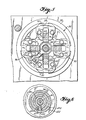
- Figure 5 is a cross section, as generally viewed in the direction of arrows 5-5 of Figure l.
- Figure 6 is a cross section, as generally viewed in the direction of arrows 6-6 of Figure 4.
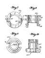
- Figure 7 is a bottom plan view of a cam for actuating one pair of centering fingers.
- Figure 8 is a cross section, as generally viewed in the direction of arrows 8-8 of Figure 7.
- Figure 9 is a top plan view of a cam for actuating the other pair of centering fingers.
- Figure 10 is a front elevation, partially broken away, of the device of Figure 9.
- Figures 11 and 12 are partial views of the pivotal centering fingers and cam means for actuating them.
- Figure 13 is a front elevation, partially broken away of a tip replacing mechanism for the centering fingers.
- Figure 14 is a partial, top plan view of the finger tip replacing mechanism.
- Figure 15 is a detailed view, partially in cross seetion,·of the vacuum nozzle and spindle.
- Figure 16 is a front elevation, partially in cross section, of a replaceable tip for the vacuum tube.
- Figure 17 is a top plan view of the device of Figure 16. :
- Throughout the drawings, like numbers are used to designate like elements, with a preferred embodiment of the invention being illustrated.
- Referring to Figure 1, a
support bracket 152 supportsmain housing 150 and provides means for attachingmain housing 150 to an overhead positioning system by which it is movable in the X and Y directions. Supported onmain houslng 150 are a Z-axis motor 160, seen in better detail in Figures 2 and 3, in which it may be seen thatgear rack 162, also seen in Figure 1, is movable up and down by mechanical connection withmotor 160 via timingbelts 166, 163, andspur gear 164.Gear 162, rack is connected to spindle 74 viabrackets gear rack 162 provides vertical reciprocation ofspindle 74.Spindle 74 is also rotatable aboutlongitudinal axis 11 via connection to sprocket 16 which, in turn, is driven by a timing belt and drivearrangement orientation motor 170. As may also be seen from Figure 1, the control of theorientation motor 170 and Z-axis motor 160 is by way ofcontroller 200. Controller 200 may include a microprocessor or the like and receives signals froin aload cell 110, as will be explained in greater detail later, in order to properly control pressure on a component during placement thereof onto a substrate by downward movement ofspindle 74. - The assembly of Figure 4 is held in
main housing 150 by retainingwasher 154 engaging the underside oflower support bearing 36.Main housing 150 is also provided with a slot (not shown) such that a yoke or the like extends through the walls ofhousing 150 in order to actuate anouter cam 122, for a reason yet to be explained. The assembly of Figure 4 has upper andlower portions hub 12 ofupper portion 10 supportingbearing 14 onspindle housing 26.Spring clip 28 fits into an annular groove ofspindle housing 26 and is clamped betweenhub 12 and asprocket 16 by tightening machine screws 17. In such a manner,upper portion 10 is fixed longitudinally relative tospindle housing 26. In order to fixupper portion 10 rotationally relative to spindlehousing 26, a speith clamping sleeve 24 is sandwiched betweenhub 12 and retainingwasher 22. Tightening ofmachine screw 23 causes speith sleeve 24 to be wedded betweenhub 12 andspindle housing 26 and to provide attachment therebetween so thathub 12 will not rotate relative to housing 26:Bearing 14 is preloaded bywave washer 20 which is retained betweenspacer 18 and retainingwasher 22. -
Spindle housing 26 is adapted for sliding along the length ofspindle 74 viabronze bearings 30. The lower portion ofspindle housing 26 is enlarged at 34 in order to provide attachment oflower bearing 36 and pivotal centeringarms 50. Referring to Figures 4 and 5, centeringarms 50 are pivotal onpins 52 which are ratained in channels in the bottom face ofspindle housing enlargement 34 byretainer plates 70.Retainer plates 70 are generally U-shaped as seen in Figure 5.Spindle housing enlargement 34 is provided with quadrature slots 38 (Fig. 5) in which the upper portions ofarms 50 may pivot, with the extent of such pivoting being limited by pins 40.Pins 56 in the upper portions ofarms 50 each support aspring 54 which, at its lower end, bears against acorresponding limit pin 40, such thatarms 50 are biased to the normal positions illustrated in Figure 4. Eacharm 50 supports a centeringfinger 66 by means of locater pins 58 andspring metal retainers 60, such that centeringfingers 66 are easily replaceable by a mechanism yet to be explained. - As seen in Figure 5, the preferred embodiment includes four centering
arms 50 such that opposed arms form a pair and two pairs ofarms 50 are at right angles to each other. Each pair of opposed arms is separately actuated for engaging and centering the body of a component by means ofcams cams arms 50 are illustrated in Figures 4, 5, and 7-12. Referring to these figures, it may be seen that acompression spring 124 biases cama 120 and 122 apart such that differential movement of thecams axis 11 may be provided according to the spring constant ofspring 124. Cam actuation may be provided by a yoke or the like extending through the wall ofhousing 150 and into engagement withcam 122 betweenflanges 123.Camming ears 128 of outer cam.122 are slidable within out awayportions 126 ofinner cam 120, such thatcam 122 is telescopic overcam 120. Accordingly, movement ofcam 122 downwardly (as viewed in Figure 4) will cause actuation of one pair of opposed centeringarms 50 by means ofcam 120 engaging the upper portions thereof. At some time thereafter, according to the spring constant ofspring 124,camming ears 128 ofcam 122 will engage the other pair of centeringarms 50. Such an arrangement allows for centering of a component along one axis such as the X axis prior to centering of the.same component along the Y axis. - Such positive cam action ensures exact centering of a component upon
longitudinal axis 11 by providing a positive, controlled rate of pivoting ofarms 50 and closure offingers 66 upon a component. Prior art centering fingers provide inaccuracies in centering according to inaccuracies in spring constants, since springs arc used to bias the centering fingers to a closed or centering position, as oppposed to the positive cam biasing of the instant invention. - Orientation of a component about
longitudinal axis 11 is provided by rotatingspindle housing 26 aboutaxis 11 viasprocket 16, which is driven byorient motor 170 via .timingbelts - In order to hold a component during such centering action, as well as to pick up such a component from supply and to place it upon a substrate, a
vacuum tube 80 is provided'. Areplaceable tip 64 of vacuum tube 80 '(as shown in Figures 16 and 17), communicates with avacuum connection nipple 104 on the oppositve end oftube 80 viaannular groove 108 surroundingspindle 74 andvacuum tube 80. Communication throughtube 80 andspindle 74 is via appropriate openings (not shown). Loss of vacuum is prevented by 0-rings 106 positioned above and belowannular groove 108. - In operation, the tooling assembly of Figures 1 and 4 is suspended above a work surface and translatable to various positions above this surface by a well known XY positioning system (not shown). Accordingly, the head may be positioned above a component supply, whereupon Z-
axis motor 160 is actuated tolower spindle 74 and allow pick-, up of a component byvacuum nozzle tip 64 in the usual manner. Thereafter, Z-axis motor 160 is again actuated to raisespindle 74 withnozzle 64 such that the tooling assembly is transversly movable above the work surface to a preselected location directly above a point on the substrate at which the component will be positioned. - Once the component has been picked up and is held on the
tip 64 ofvacuum nozzle 80, the centering of the component upon thetip 64 may be accomplished by actuation of centeringarms 50, as explained earlier. After or during such centering, the component may be oriented aboutlongitudinal axis 11 by engaging centeringfingers 66 with the component and rotating spindle housing 26 together.withspindle 74 viasprocket 16 andorientation motor 170, thus providing control of the component during reorienting thereof and avoiding any possible problems of miscentering of the component during such reorienting. Having properly oriented and centered the component upontip 64,spindle 74 may be lowered by Z-axis motor 160 to position the component upon the substrate, whereupon the vacuum is interrupted. - Protection of the component, the substrate and tooling assembly from damaging placement pressures, as well as being able to sense when the component has reached the substrate, is provided by a load cell assembly by which the placement pressure is sensed and communicated to
controller 200. As may be seen from Figure 4, aload cell 110 is supported bybracket 112 abovespindle 74.Load cell 110 is fixed relative to spindle 74, andvacuum tube 80 is telescopic withinspindle 74 as limited byslot 86 andcross pin 84. Acompression spring 88 is sandwiched between the top ofvacuum tube 80 and the bottom of apiston 90, with the top ofpiston 90 engaging aball 114 which, in turn, engages a levelingplate 116. Levelingplate 116 andball 114 provide for even distribution of forces to theload cell 110, typically a piezoelectric crystal. Accordingly, the pressure encountered by placing the component on the substrate is transmitted (viavacuum tube 80,spring 88,piston 90,ball 114, and leveler plate 116) to theload cell 110.Spring 88 is appropriately selected so that the compression thereof is the proper function of the pressure applied, in order that, upon sensing the pressure upon the component during sandwiching thereof between thenozzle tip 64 and the substrate upon which it is being placed, appropriate Z-axis control may be actuated In order to provide the protection and sensing mentioned above. For instance, in a prototype of thisembodiment 40 grams of placement pressure corresponds to 0.030 inches of spring compression and 80 grams of pressure corresponds to 0.060 inches of spring compression. As may be appreciated, there is a differential travel of thevacuum tube 80 in relation to the placement pressure, being applied and sensed. The linear voltage output ofload cell 110, indicating the placement pressure, is transmitted to a controller 200 (Figure 1) for the appropriate control of Z-axis motor 160. Such a linear output from theload cell 110 allows exacting Z-axis control of thevacuum nozzle 80. - A particular improvement of the instant invention over the prior art incorporates interchangeable centering
fingers 66, along with an interchangeable vacuum nozzle 611, so that high speed, automated changing of the centeringfingers 66 may be effected according to the sizes and shapes of thefinger tips 66 required of the components being operated upon. As well as being applicable to manual changing of thetips 66, such a feature is of utmost importance in the high speed automated machinery now used in population of -printed circuit t boards. The set-up time normally required in order to operate on various configurations and sizes of components is something to be greatly avoided when at all possible. By the instant invention, the usual practice of changing complete head assemblies is easily avoided by either of two methods of adapting to such varying components. - In one method of doing so, centering
arms 50 are easily removable and replaceable, as by removing C-shapedretaining plates 70 and pullingarms 50 downwardly (as viewed in Figure 4).Different arms 50 are replaceable therein by the reverse action, i.e., slipping the arms upwardly in thequadrature slots 38 ofspindle housing enlargement 34 and replacing retainingplates 70. - A still faster method for changing to the tooling necessary to center a particular component is provided by the apparatus of Figures' 13 and 14, wherein only one of the replacement centering
finger tips 66 is shown (in order to illustrate operation of the apparatus). Although showing only onereplaceable finger 66, each of the four positions ofreplacement mechanism 180, corresponding to the positions of centeringarms 50, will have theappropriate replacement tips 66 located therein. - In operation, the
head assembly 152 of Figures 4 and 5 is translated to a position above a tooling mechanism: 180. Whenhead assembly 152 already has centeringfingers 50replacement mechanism 180 will be empty so that, upon firingcylinder 182 to open the rotatabletip grabber arm 186 against the bias of spring 187,cylinder 184 may be fired to raisemechanism 180 and receivetips 66 in quadrature spacednests 181 ofmechanism 180. Thereafter,cylinder 182 is reverse actuated allowing a spring 187 to close each. gripper 186 upon thecorresponding finger tip 66. At this time,cylinder 184 is again actuated to lower themechanism 180 such thatfinger tips 66 are disengaged fromspring holders 60 of centeringarms 50. Thereafter, the head assembly is repositioned above anotherreplacement mechanism 180 which already has centeringtips 66 secured therein, and a reverse procedure is performed in order to load new tips onto the centeringarms 50. - An additional feature of the invention is the provision for stopping the
vacuum tube 80 at various heights in the upstroke according to the size and/or configuration of the component body. With such provision, each set oftips 66 may accommodate more than one pnrticular size and or configuration of component at more than one vertical level of thetip 66. Accuracy for this feature is provided bycontroller 20 and Z-axis servomotor 160.
Claims (10)
Applications Claiming Priority (2)
| Application Number | Priority Date | Filing Date | Title |
|---|---|---|---|
| US658827 | 1984-10-09 | ||
| US06/658,827 US4611397A (en) | 1984-10-09 | 1984-10-09 | Pick and place method and apparatus for handling electrical components |
Publications (2)
| Publication Number | Publication Date |
|---|---|
| EP0178167A2 true EP0178167A2 (en) | 1986-04-16 |
| EP0178167A3 EP0178167A3 (en) | 1987-09-30 |
Family
ID=24642872
Family Applications (1)
| Application Number | Title | Priority Date | Filing Date |
|---|---|---|---|
| EP85307232A Withdrawn EP0178167A3 (en) | 1984-10-09 | 1985-10-09 | Pick and place method and apparatus for handling electrical components |
Country Status (4)
| Country | Link |
|---|---|
| US (1) | US4611397A (en) |
| EP (1) | EP0178167A3 (en) |
| JP (1) | JP2589290B2 (en) |
| CA (1) | CA1238985A (en) |
Cited By (10)
| Publication number | Priority date | Publication date | Assignee | Title |
|---|---|---|---|---|
| EP0253228A2 (en) * | 1986-07-04 | 1988-01-20 | Matsushita Electric Industrial Co., Ltd. | Mounting head exchange arrangement for part mounting machine |
| EP0282140A2 (en) * | 1987-03-13 | 1988-09-14 | Koninklijke Philips Electronics N.V. | Gripping device |
| WO1989000768A1 (en) * | 1987-07-20 | 1989-01-26 | Hughes Aircraft Company | Rotatable pick and place vacuum sense head for die bonding apparatus |
| EP0329630A2 (en) * | 1988-02-16 | 1989-08-23 | International Business Machines Corporation | Method and apparatus for positioning electrical components |
| FR2638669A1 (en) * | 1988-11-10 | 1990-05-11 | Sree | Robot allowing insertion and soldering of electronic components onto a supporting board |
| EP0476912A2 (en) * | 1990-09-19 | 1992-03-25 | AT&T Corp. | Electronic device manipulating apparatus and method |
| EP0552921A1 (en) * | 1992-01-21 | 1993-07-28 | Emhart Inc. | Compound tool drive |
| EP0552920A1 (en) * | 1992-01-21 | 1993-07-28 | Emhart Inc. | Tool holder for surface mount machine |
| EP0552914A1 (en) * | 1992-01-21 | 1993-07-28 | Emhart Inc. | Tool holder assembly for surface mount machine |
| EP1906723A2 (en) * | 2006-09-28 | 2008-04-02 | Siemens Aktiengesellschaft | Slide element for a construction element holding device with central load transmission |
Families Citing this family (38)
| Publication number | Priority date | Publication date | Assignee | Title |
|---|---|---|---|---|
| WO1985003405A1 (en) * | 1984-01-23 | 1985-08-01 | Dyna/Pert - Precima Limited | Pick-up head for handling electrical components |
| WO1985003404A1 (en) * | 1984-01-23 | 1985-08-01 | Dyna/Pert - Precima Limited | Head for handling electrical components |
| US4733457A (en) * | 1985-02-04 | 1988-03-29 | Metalmeccanica Gori & Zucchi M.G.Z. S.P.A. | Apparatus for the automation of operative systems with mechanical hand or the like |
| US4705311A (en) * | 1986-02-27 | 1987-11-10 | Universal Instruments Corporation | Component pick and place spindle assembly with compact internal linear and rotary displacement motors and interchangeable tool assemblies |
| US4759124A (en) * | 1987-04-28 | 1988-07-26 | Universal Instruments Corp. | Method and apparatus for controlling component pickup and placement pressures |
| JPH0777308B2 (en) * | 1987-05-28 | 1995-08-16 | 三洋電機株式会社 | Parts mounting device |
| US5127692A (en) * | 1987-10-20 | 1992-07-07 | Canon Kabushiki Kaisha | Article gripping apparatus |
| SE8800779L (en) * | 1988-03-04 | 1989-09-05 | Mydata Automation Ab | MOVABLE TOOL HEAD FOR MOUNTING MACHINES AND ROTARY, AXIAL LED MOVED AXEL BEARING SUCH A HEAD |
| JPH0235743A (en) * | 1988-07-26 | 1990-02-06 | Mitsubishi Electric Corp | Manufacturing device for semiconductor device |
| USRE35027E (en) * | 1988-09-22 | 1995-08-29 | Delaware Capital Formation, Inc. | Pick and place method and apparatus |
| US5040291A (en) * | 1990-05-04 | 1991-08-20 | Universal Instruments Corporation | Multi-spindle pick and place method and apparatus |
| JP2680773B2 (en) * | 1991-10-11 | 1997-11-19 | 三洋電機株式会社 | Pressurizing force control device in component mounting device |
| JP2798834B2 (en) * | 1991-12-02 | 1998-09-17 | 三洋電機株式会社 | Electronic component mounting device |
| US5201696A (en) * | 1992-05-05 | 1993-04-13 | Universal Instruments Corp. | Apparatus for replacement of vacuum nozzles |
| DE4223516C1 (en) * | 1992-07-17 | 1993-07-22 | Viktor Dipl.-Ing. 5300 Bonn De Schatz | |
| KR970010118B1 (en) * | 1994-09-16 | 1997-06-21 | Lg Ind Systems Co Ltd | Head tool of surface mounter and automatic exchanger |
| JPH08279697A (en) * | 1995-04-10 | 1996-10-22 | Fuji Mach Mfg Co Ltd | Electronic component mounting head, electronic component mounting equipment and electronic component mounting method |
| US5649356A (en) * | 1995-09-22 | 1997-07-22 | Universal Instruments Corporation | Method and apparatus for supplying and placing components |
| JPH09139961A (en) * | 1995-11-14 | 1997-05-27 | Fujitsu Ltd | Automatic line distribution device |
| JPH09312682A (en) * | 1996-05-22 | 1997-12-02 | Fujitsu Ltd | Device and method for inserting and extracting connection pin |
| JPH1027996A (en) | 1996-07-10 | 1998-01-27 | Matsushita Electric Ind Co Ltd | Electronic device mounter |
| JP4082770B2 (en) * | 1998-02-02 | 2008-04-30 | 富士機械製造株式会社 | Electric component conveying apparatus and holder replacement method and apparatus therefor |
| US6315189B1 (en) * | 1998-10-13 | 2001-11-13 | Texas Instruments Incorporated | Semiconductor package lead plating method and apparatus |
| US6385842B1 (en) | 2000-01-14 | 2002-05-14 | Delaware Capital Formation, Inc. | Tube feeder having a zone on which components can pivot |
| JP2002127065A (en) * | 2000-10-23 | 2002-05-08 | Fuji Mach Mfg Co Ltd | Nozzle installing device |
| JP2002200585A (en) * | 2000-12-28 | 2002-07-16 | Fuji Mach Mfg Co Ltd | Device for holding electrical component |
| DE50214847D1 (en) * | 2001-10-31 | 2011-02-17 | Komax Holding Ag | Handling device for wire line, insertion machine and insertion method with such a handling device |
| JP3717834B2 (en) * | 2001-11-15 | 2005-11-16 | 富士通メディアデバイス株式会社 | Electronic component adsorption device and electronic component testing apparatus equipped with the same |
| JP4166620B2 (en) * | 2003-05-13 | 2008-10-15 | オリンパス株式会社 | Semiconductor bonding equipment |
| JP4468195B2 (en) * | 2005-01-31 | 2010-05-26 | 富士通株式会社 | IDENTIFICATION UNIT AND PROCESSING DEVICE FOR PROCESSING DEVICE |
| CN104669284A (en) * | 2013-11-30 | 2015-06-03 | 深圳富泰宏精密工业有限公司 | Material sucking and discharging device |
| ES2549546B1 (en) * | 2014-04-28 | 2016-09-09 | Emdep-2, S.L. | Device and procedure for inserting elements in fuse boxes |
| US10155313B2 (en) * | 2015-04-23 | 2018-12-18 | Massachusetts Institute Of Technology | Discrete assemblers utilizing conventional motion systems |
| ITUB20160018A1 (en) * | 2016-01-25 | 2017-07-25 | Officina Meccanica Di Prec G 3 Di Gamba Walter & C S N C | Picker for manipulator of integrated circuits |
| SE545308C2 (en) | 2016-05-27 | 2023-06-27 | Universal Instruments Corp | Dispensing head having a nozzle heater device, system and method |
| KR102425309B1 (en) * | 2016-10-12 | 2022-07-26 | 삼성전자주식회사 | Apparatus for correcting a paralleism between a bonding head and a stage and chip bondder including the same |
| US11375651B2 (en) | 2018-02-26 | 2022-06-28 | Universal Instruments Corporation | Dispensing head, nozzle and method |
| SG11202008085SA (en) | 2018-02-26 | 2020-09-29 | Universal Instruments Corp | Dispensing head, nozzle and method |
Citations (6)
| Publication number | Priority date | Publication date | Assignee | Title |
|---|---|---|---|---|
| US3731867A (en) * | 1971-07-19 | 1973-05-08 | Motorola Inc | Vacuum die sensor apparatus and method for a semiconductor die bonding machine |
| GB2034613A (en) * | 1978-11-09 | 1980-06-11 | Tokyo Shibaura Electric Co | Method and apparatus for mounting electronic components |
| GB2108015A (en) * | 1981-08-24 | 1983-05-11 | Tdk Electronics Co Ltd | Apparatus for mounting chip type circuit elements on printed circuit boards |
| EP0092274A1 (en) * | 1982-04-16 | 1983-10-26 | Koninklijke Philips Electronics N.V. | Device for transferring an electric or electronic component to a mounting board |
| US4473247A (en) * | 1981-02-13 | 1984-09-25 | Matsushita Electric Industrial Co., Ltd. | Component mounting apparatus |
| US4515507A (en) * | 1983-06-01 | 1985-05-07 | Fuji Machine Mfg. Co., Ltd. | Method and apparatus for holding and centering electronic component |
Family Cites Families (9)
| Publication number | Priority date | Publication date | Assignee | Title |
|---|---|---|---|---|
| US3337941A (en) * | 1965-05-27 | 1967-08-29 | Ibm | Recycle control circuit for a chip positioning machine |
| US3453714A (en) * | 1967-02-10 | 1969-07-08 | Ibm | Vacuum operated chip placement head |
| JPS5599795A (en) * | 1979-01-25 | 1980-07-30 | Matsushita Electric Ind Co Ltd | Device for mounting electronic part |
| US4438559A (en) * | 1980-06-27 | 1984-03-27 | Fuji Machine Mfg. Co. Ltd. | Apparatus for automatically mounting non-lead electronic components on printed-circuit |
| JPS5853887A (en) * | 1981-09-26 | 1983-03-30 | 富士機械製造株式会社 | Method of mounting leadless electronic part on printed board or the like |
| JPS57184294A (en) * | 1982-03-04 | 1982-11-12 | Matsushita Electric Ind Co Ltd | Device for mounting electronic part |
| JPS597531A (en) * | 1982-07-07 | 1984-01-14 | Agency Of Ind Science & Technol | Press fit controller |
| JPS59120527U (en) * | 1983-02-02 | 1984-08-14 | 三菱電機株式会社 | Automatic parts replacement device |
| JPS5986299A (en) * | 1983-10-04 | 1984-05-18 | 富士機械製造株式会社 | Holder for positioning electronic part |
-
1984
- 1984-10-09 US US06/658,827 patent/US4611397A/en not_active Expired - Lifetime
-
1985
- 1985-10-07 CA CA000492416A patent/CA1238985A/en not_active Expired
- 1985-10-09 JP JP60223867A patent/JP2589290B2/en not_active Expired - Lifetime
- 1985-10-09 EP EP85307232A patent/EP0178167A3/en not_active Withdrawn
Patent Citations (6)
| Publication number | Priority date | Publication date | Assignee | Title |
|---|---|---|---|---|
| US3731867A (en) * | 1971-07-19 | 1973-05-08 | Motorola Inc | Vacuum die sensor apparatus and method for a semiconductor die bonding machine |
| GB2034613A (en) * | 1978-11-09 | 1980-06-11 | Tokyo Shibaura Electric Co | Method and apparatus for mounting electronic components |
| US4473247A (en) * | 1981-02-13 | 1984-09-25 | Matsushita Electric Industrial Co., Ltd. | Component mounting apparatus |
| GB2108015A (en) * | 1981-08-24 | 1983-05-11 | Tdk Electronics Co Ltd | Apparatus for mounting chip type circuit elements on printed circuit boards |
| EP0092274A1 (en) * | 1982-04-16 | 1983-10-26 | Koninklijke Philips Electronics N.V. | Device for transferring an electric or electronic component to a mounting board |
| US4515507A (en) * | 1983-06-01 | 1985-05-07 | Fuji Machine Mfg. Co., Ltd. | Method and apparatus for holding and centering electronic component |
Cited By (15)
| Publication number | Priority date | Publication date | Assignee | Title |
|---|---|---|---|---|
| EP0253228A2 (en) * | 1986-07-04 | 1988-01-20 | Matsushita Electric Industrial Co., Ltd. | Mounting head exchange arrangement for part mounting machine |
| EP0253228A3 (en) * | 1986-07-04 | 1990-04-11 | Matsushita Electric Industrial Co., Ltd. | Mounting head exchange arrangement for part mounting machine |
| EP0282140A3 (en) * | 1987-03-13 | 1990-05-16 | Koninklijke Philips Electronics N.V. | Gripping device |
| EP0282140A2 (en) * | 1987-03-13 | 1988-09-14 | Koninklijke Philips Electronics N.V. | Gripping device |
| WO1989000768A1 (en) * | 1987-07-20 | 1989-01-26 | Hughes Aircraft Company | Rotatable pick and place vacuum sense head for die bonding apparatus |
| EP0329630A2 (en) * | 1988-02-16 | 1989-08-23 | International Business Machines Corporation | Method and apparatus for positioning electrical components |
| EP0329630A3 (en) * | 1988-02-16 | 1991-02-06 | International Business Machines Corporation | Method and apparatus for positioning electrical components |
| FR2638669A1 (en) * | 1988-11-10 | 1990-05-11 | Sree | Robot allowing insertion and soldering of electronic components onto a supporting board |
| EP0476912A2 (en) * | 1990-09-19 | 1992-03-25 | AT&T Corp. | Electronic device manipulating apparatus and method |
| EP0476912A3 (en) * | 1990-09-19 | 1992-09-09 | American Telephone And Telegraph Company | Electronic device manipulating apparatus and method |
| EP0552921A1 (en) * | 1992-01-21 | 1993-07-28 | Emhart Inc. | Compound tool drive |
| EP0552920A1 (en) * | 1992-01-21 | 1993-07-28 | Emhart Inc. | Tool holder for surface mount machine |
| EP0552914A1 (en) * | 1992-01-21 | 1993-07-28 | Emhart Inc. | Tool holder assembly for surface mount machine |
| EP1906723A2 (en) * | 2006-09-28 | 2008-04-02 | Siemens Aktiengesellschaft | Slide element for a construction element holding device with central load transmission |
| EP1906723A3 (en) * | 2006-09-28 | 2010-01-27 | Siemens Electronics Assembly Systems GmbH & Co. KG | Slide element for a construction element holding device with central load transmission |
Also Published As
| Publication number | Publication date |
|---|---|
| EP0178167A3 (en) | 1987-09-30 |
| CA1238985A (en) | 1988-07-05 |
| US4611397A (en) | 1986-09-16 |
| JP2589290B2 (en) | 1997-03-12 |
| JPS61216388A (en) | 1986-09-26 |
Similar Documents
| Publication | Publication Date | Title |
|---|---|---|
| US4611397A (en) | Pick and place method and apparatus for handling electrical components | |
| US4135630A (en) | Centering device for automatic placement of chip components in hybrid circuits | |
| EP0065604B1 (en) | Leadless chip placement machine for printed circuit boards | |
| US4872258A (en) | Pick and place method and apparatus | |
| US5323528A (en) | Surface mount placement system | |
| EP0257546B1 (en) | Chip-placement machine with test function | |
| JPH0315359B2 (en) | ||
| CN106981444B (en) | Hot-pressing bonding device | |
| JP2001051018A (en) | Ic tester | |
| US4501064A (en) | Micro component assembly machine | |
| EP0092292B1 (en) | Method of and device for placing chip-type electrical and/or electronic components on a substrate | |
| USRE35027E (en) | Pick and place method and apparatus | |
| US5056844A (en) | Multiple jaw centering head structure for surface mounted component placement machines | |
| US4956911A (en) | Tool for repairing surface mounted components on printed circuit board | |
| CN1983549A (en) | Apparatus and method for arranging devices for processing | |
| US5180975A (en) | Positioning device and IC conveyor utilizing the same | |
| US5106138A (en) | Linear tweezers | |
| JPH0375318B2 (en) | ||
| JPS6163089A (en) | Automatic electronic part mounting device | |
| JPS59130500A (en) | Method of automatically mounting printed circuit board with semiconductor element containing integrated circuit and device for executing same method | |
| JPH0247118B2 (en) | ||
| JP2001177296A (en) | Mounting machine for surface mounting component, and method for mounting surface mounting component | |
| US4573254A (en) | Apparatus for maintaining electronic component pin alignment | |
| JPH0715916B2 (en) | Bonding device | |
| JPS6285491A (en) | Device for mounting part |
Legal Events
| Date | Code | Title | Description |
|---|---|---|---|
| PUAI | Public reference made under article 153(3) epc to a published international application that has entered the european phase |
Free format text: ORIGINAL CODE: 0009012 |
|
| AK | Designated contracting states |
Kind code of ref document: A2 Designated state(s): AT BE CH DE FR GB IT LI LU NL SE |
|
| PUAL | Search report despatched |
Free format text: ORIGINAL CODE: 0009013 |
|
| AK | Designated contracting states |
Kind code of ref document: A3 Designated state(s): AT BE CH DE FR GB IT LI LU NL SE |
|
| 17P | Request for examination filed |
Effective date: 19880321 |
|
| 17Q | First examination report despatched |
Effective date: 19900410 |
|
| STAA | Information on the status of an ep patent application or granted ep patent |
Free format text: STATUS: THE APPLICATION IS DEEMED TO BE WITHDRAWN |
|
| 18D | Application deemed to be withdrawn |
Effective date: 19930529 |
|
| RIN1 | Information on inventor provided before grant (corrected) |
Inventor name: LOVELL, EDWARD J. Inventor name: JANISIEWICZ, STANLEY W. |