EP0177919B1 - Method for calibrating transformation matrix of a force sensor - Google Patents
Method for calibrating transformation matrix of a force sensor Download PDFInfo
- Publication number
- EP0177919B1 EP0177919B1 EP85112676A EP85112676A EP0177919B1 EP 0177919 B1 EP0177919 B1 EP 0177919B1 EP 85112676 A EP85112676 A EP 85112676A EP 85112676 A EP85112676 A EP 85112676A EP 0177919 B1 EP0177919 B1 EP 0177919B1
- Authority
- EP
- European Patent Office
- Prior art keywords
- force sensor
- force
- robot
- transformation matrix
- sensor
- Prior art date
- Legal status (The legal status is an assumption and is not a legal conclusion. Google has not performed a legal analysis and makes no representation as to the accuracy of the status listed.)
- Expired
Links
Images

Classifications
-
- G—PHYSICS
- G01—MEASURING; TESTING
- G01L—MEASURING FORCE, STRESS, TORQUE, WORK, MECHANICAL POWER, MECHANICAL EFFICIENCY, OR FLUID PRESSURE
- G01L25/00—Testing or calibrating of apparatus for measuring force, torque, work, mechanical power, or mechanical efficiency
-
- B—PERFORMING OPERATIONS; TRANSPORTING
- B25—HAND TOOLS; PORTABLE POWER-DRIVEN TOOLS; MANIPULATORS
- B25J—MANIPULATORS; CHAMBERS PROVIDED WITH MANIPULATION DEVICES
- B25J13/00—Controls for manipulators
- B25J13/08—Controls for manipulators by means of sensing devices, e.g. viewing or touching devices
- B25J13/085—Force or torque sensors
-
- B—PERFORMING OPERATIONS; TRANSPORTING
- B25—HAND TOOLS; PORTABLE POWER-DRIVEN TOOLS; MANIPULATORS
- B25J—MANIPULATORS; CHAMBERS PROVIDED WITH MANIPULATION DEVICES
- B25J9/00—Programme-controlled manipulators
- B25J9/16—Programme controls
- B25J9/1679—Programme controls characterised by the tasks executed
- B25J9/1692—Calibration of manipulator
-
- G—PHYSICS
- G01—MEASURING; TESTING
- G01L—MEASURING FORCE, STRESS, TORQUE, WORK, MECHANICAL POWER, MECHANICAL EFFICIENCY, OR FLUID PRESSURE
- G01L5/00—Apparatus for, or methods of, measuring force, work, mechanical power, or torque, specially adapted for specific purposes
- G01L5/16—Apparatus for, or methods of, measuring force, work, mechanical power, or torque, specially adapted for specific purposes for measuring several components of force
- G01L5/161—Apparatus for, or methods of, measuring force, work, mechanical power, or torque, specially adapted for specific purposes for measuring several components of force using variations in ohmic resistance
- G01L5/1627—Apparatus for, or methods of, measuring force, work, mechanical power, or torque, specially adapted for specific purposes for measuring several components of force using variations in ohmic resistance of strain gauges
-
- G—PHYSICS
- G01—MEASURING; TESTING
- G01L—MEASURING FORCE, STRESS, TORQUE, WORK, MECHANICAL POWER, MECHANICAL EFFICIENCY, OR FLUID PRESSURE
- G01L5/00—Apparatus for, or methods of, measuring force, work, mechanical power, or torque, specially adapted for specific purposes
- G01L5/22—Apparatus for, or methods of, measuring force, work, mechanical power, or torque, specially adapted for specific purposes for measuring the force applied to control members, e.g. control members of vehicles, triggers
- G01L5/226—Apparatus for, or methods of, measuring force, work, mechanical power, or torque, specially adapted for specific purposes for measuring the force applied to control members, e.g. control members of vehicles, triggers to manipulators, e.g. the force due to gripping
Definitions
- the present invention relates to detecting method of a force sensor for automatically detecting a transformation matrix indicative of the relationship between the strain voltage and the force (force and torque are referred to as a "force” as a general term) in a six degree of freedom force sensor (namely, which can detect three components of the force and three components of the torque) which is attached to a robot.
- a force sensor is attached to a robot and finds out the relation between the force and the strain voltage in the relevant portion.
- the relation between the strain voltage and the force is unconditionally determined and it is expressed by the following mathematical expression.
- F is a force which is applied to the sensor and V is a strain voltage.
- [B] is a constant showing the relation between F and V and is generally called a transformation matrix. and V can be together expressed by vectors.
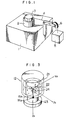
- a measuring apparatus in this conventional example is shown in Fig. 1.
- a force sensor 2 is fixedly attached to a base 1.
- a cable 4 is attached to a moving portion 3 of the force sensor 2 and a sash weight 5 depends from the end of the cable 4 through a pulley 6.
- the weight of the sash weight and the attaching direction of the cable 4 are changed by such an apparatus. Due to this, the data necessary for the transformation matrix is obtained and the transformation matrix is calculated.
- this conventional example is an effective method of obtaining the transformation matrix, it has a problem such that a large amount of labor and a long time are needed.
- the transformation matrix has to be calculated by removing the force sensor from the robot every time they are varied.
- a hand portion of a robot is replaced by a calibrated component detector and a load member to calibrate the component detector of the robot.
- Dependent claim 2 is directed on a preferred embodiment of the method according to the invention.
- the present invention is made by paying an attention to the points such that the state whereby a robot is set into different postures by attaching a force sensor and standard works to the robot is equivalent to the state whereby many independent forces (forces and moments) are applied to the force sensor and that the postures and their coordinates can be simultaneously detected from the robot itself.
- an attention is paid to the point such that the transformation matrix can be automatically calibrated on the basis of the postures and coordinates which are detected from the robot itself by merely setting the robot into a few kinds of different postures by swinging the wrist on the basis of certain conditions in the state whereby the force sensor and the proper standard work are attached to the robot.
- the present invention has a feature such that (n+1) or more linear independent forces are applied and the transformation matrix [A] including a bias value is calibrated.
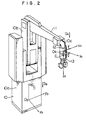
- Fig. 2 is a diagram showing a robot to which a force sensor is attached.
- a robot 10 having six degrees of freedom for example, there has been proposed in EP-A2-78522.
- the robot 10 is equipped with a swivel pedestal 10a, an upper arm 10b and a forearm 11.
- a wrist 10c having three degrees of freedom is mounted at the end of the forearm 11.
- a force sensor 12 is attached between the wrist 10c and a hand portion 13.
- the force sensor 12 is a strain gauge and generates strain voltages corresponding to the forces regarding six degrees of freedom in response to the force applied to the hand portion 13.
- the term "force” denotes both of the force and the moment and this force is a six-dimensional vector.
- the coordinate axes (O b ⁇ x b ⁇ y b ⁇ z b ) of the base and the coordinate axes (O s ⁇ x s ⁇ y s ⁇ z s ) of the force sensor 12 are different as shown in Fig. 2.
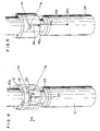
- the force sensor 12 comprises an external. member 21, an internal member 23, and thin plate members 22.
- the external member 21 is fixed to the wrist 10c and the internal member 23 is fixed to the hand portion 13.
- the thin plate members 22 couple the internal member 23 with the external member 21.
- Strain gauges 24 are attached to portions of the thin plate members 22.
- the force When a force is applied to the hand portion 13 in such an arrangement, the force is propagated to the internal member 23 coupled to the hand portion 13, causing the strain gauges 24 to be deformed through the coupling plates 22. The voltages corresponding to those deformations are generated at output terminals of the strain gauges 24 and are detected.
- the relationship between the force and the strain voltage is unconditionally determined by properly setting the number, dimensions, and attaching positions of the thin plate portions, and the number and attaching positions of the strain gauges, and the like. Therefore, the force can be detected from the magnitude of the strain voltage.
- the relation between the force and the strain voltage is decided by the rigidity transformation matrix [B].
- a control unit 40 is connected to the robot 10 in order to allow the robot to perform a predetermined operation in response to a force signal detected from the force sensor 12 and further in accordance with a program stored in the control unit 40.
- this robot is the joint type robot 10 comprising: the swivel pedestal 10a which rotates around the vertical axis on the base; the upper arm 10b which rotates around the horizontal axis on the swivel pedestal 10a; the forearm 11 rotatably coupled with the end of the upper arm 10b; and the wrist 10c rotatably mounted at the end of the forearm 11 so as to have three degrees of freedom as illustrated in the diagram.
- the force sensor 12 is attached to the end of the wrist 10c of the joint type robot 10. The force applied to the robot is detected by the force sensor 12.
- the present position of the robot is detected by way of output signals from encoders PE or the like coupled with motors M or the like for driving the respective operating elements 10a, 10b, 11, and 10c of the robot 10.
- tachogenerators TG or the like are coupled with the motors M such that the rotating speeds of the respective operating elements can be detected.
- a proximity sensor or the like to detect the distance between the wrist 10c of the robot and an object may be attached to the wrist 10c.
- the position 8 of the robot, the voltage V detected from the force sensor 12, and the like are supplied to the control unit 40 constituted by a microcomputer. Further, the instruction values such as the position x r , postures f, g, h, force F e , weight of the weight, position of the center of gravity of the weight, weight of the hand portion, position of the center of gravity of the hand portion, internal weight of the force sensor, position of the center of gravity of the force sensor, instructions of predetermined points to form the operating path, and the like are inputted to the control unit 40 from a control table 45 or the like.
- control unit 40 is constituted by, for example: a microprocessor 41; a RAM 42; a ROM 43; an arithmetic logic unit 44; an interface circuit (I/F) 46 to connect the control unit 40 with the control table 45; a D/A converter 50; a counter 51 to count the outputs from the encoders PE; an A/D converter 53 to convert an analog signal outputted from an amplifier 52 to a digital signal; and a bus line 47 to connect the above-mentioned components.
- a microprocessor 41 a RAM 42; a ROM 43; an arithmetic logic unit 44; an interface circuit (I/F) 46 to connect the control unit 40 with the control table 45; a D/A converter 50; a counter 51 to count the outputs from the encoders PE; an A/D converter 53 to convert an analog signal outputted from an amplifier 52 to a digital signal; and a bus line 47 to connect the above-mentioned components.
- the robot operates only by the force which is applied to the hand portion 13. Namely, the passive mechanism is constituted.
- the movement is determined by these instruction values.
- control unit 40 generates an instruction value of the joint angular velocity ⁇ of the robot to servo amplifiers 49, thereby making the robot 10 operative.
- the signals from the encoders PE of the respective joints of the robot are counted by the counter 51 and the present position 8 is received and the coordinate conversion from the joint angle 8 into the orthogonal coordinates x of the hand system is performed.
- this coordinate conversion is performed by the arithmetic logic unit 44 in response to a command from the microprocessor 41.
- the external force F applied to the robot is detected by the force sensor 12.
- the control unit 40 receives the external force F through the A/D converter 53 as a voltage V of the strain gauge constituting the force sensor 12.
- the force calculating section 41,43,44 receives V and x(8) and first converts the voltage V of the strain gauge into the force by way of the transformation matrix [B] or the like of the strain/force. In the actual process, this voltage to force conversion is performed by the ALU 44 in response to a command from the microprocessor 41. Next, in the case where the weight of an object which is grasped by the hand portion 13 and the hand is large, the values which are applied to the force sensor 12 differ in dependence on the posture of the hand. Therefore, the rigidity transformation matrix [B] is calibrated on the basis of the posture and position 8 of the hand portion 13, thereby eliminating the influence due to the posture of the hand and calculating the force F actually applied to the robot.
- the value calculated in this manner is F and given to the main control section 41, 43, 44.
- the velocity v at which the hand portion 13 operates is calculated by the main control section.
- v is the value in the coordinate system fixed to the hand, this value is converted to the velocity v o in the coordinate system of the base by way of the coordinate conversion.
- the angular velocity ⁇ of each axis of the robot is calculated by the joint angle calculating section on the basis of the velocity V 0 in the orthogonal coordinate system.
- J -1 is called an anti-Jacobian matrix and its elements are the function of each join angle 8 of the robot.
- the servo amplifiers 49 operate on the basis of the angular velocity ⁇ , so that the motors M for the respective joints of the robot are made operative.
- the instruction values F e and X r of the force and position are also inputted to the main control section, and the velocity v of the hand portion is outputted.
- the force F applied to the force sensor 12 has to be calculated from the voltage value V detected from the force sensor 12. It is necessary to preliminarily calibrate and determine the rigidity transformation matrix [B] for calculation of the force F.
- a method of calibrating the transformation matrix [B] of the force sensor, which is a feature of the present invention, in the state whereby the force sensor was attached to the robot in this manner will then be practically described hereinbelow.
- the strain voltage V of the force sensor 12 can be specified by Where, V d is a voltage generated when no force is applied to the force sensor 12 (the internal weight is also regarded as a force). This voltage V d is an n-dimensional vector. V o is a voltage generated when a force was actually applied to the force sensor 12 (internal weight is regarded as a force). This voltage V o is also an n-dimensional vector. In this case, n ⁇ 6.
- the force F is a force applied to the force sensor 12 and is considered in the sensor coordinate system.
- This force F consists of a force and a moment and is a six-dimensional vector.
- the internal weight W in and the position d in of center of gravity of the internal weight (this position is a value expressed by the sensor coordinate system (hereinafter, referred to as an S system) indicated by O s ⁇ x s ⁇ y s ⁇ z s shown in Fig. 2) can be preliminarily obtained using the design drawing or the like; therefore, they may be considered as known values which can be inputted from the control table 45.
- S system sensor coordinate system
- the force sensor 12 is attached to the end of the forearm 11 of the robot. Further, nothing is attached to the end of the force sensor 12.
- the robot 10 is controlled by inputting the positions x, y, z and positions f, g, h, and the like from the control table 45 shown in Fig. 9 in a manner such that the coordinate axis Z s of the sensor coordinate system faces downward, namely, in the direction of the gravity.
- the strain voltage is measured by the force sensor 12 under the condition whereby the coordinate axis Z s faces in the direction of the gravity. This strain voltage is set to V dow .
- the coordinate axis Z s of the sensor coordinate system is set into the upward posture and the strain voltage is measured by the force sensor 12 in this posture. This strain voltage is set to V u p.
- V d is derived from the following equation.
- equation (4) is correct and the voltage V d is derived from equation (4).
- a standard work is attached to the force sensor 12.
- Fig. 4 shows a perspective view in the case where a standard work is attached. It is assumed that a standard work 31 has the weight W st and the position of the center of gravity in the sensor coordinate system is d st . These W st and d st can be together inputted from the control table 45 and are known values.
- the unit vector indicative of the direction of the gravity is Ub in the coordinate system (O b ⁇ x b ⁇ y b ⁇ z b ) of the base of the wrist 10c.
- This U s is a known value which can be obtained on the basis of the position 8 which is detected from the encoder PE.
- the unit vector indicative of the direction of the center of gravity in the sensor coordinate system assumes u s .
- the unit vectors in the directions of the respective coordinate axes in the sensor coordinate system assume f, 9 and h. The following equation is satisfied under these conditions.
- F is a six-dimensional vector.
- Six elements of the vector F denote the components of the force in the x, y and z axes and the components of the moment in the x, y and z axes.
- the strain voltage V is obtained from equation (2). Namely, the actual strain voltage V o is derived and the voltage V d is subtracted from this V o , so that the value of V can be derived.
- the process mentioned in the above item (3) is one example of measurement under the condition whereby only one posture is set and one standard work is attached. In the actual situation, measurement is performed under the respective conditions whereby the posture of the robot is varied and the standard work is changed (the weight and the position of the center of gravity are changed) in response to commands from the control table 45.
- Equation (14) can be combined as a matrix expression.
- [ F 1 , F 2 , ..., F m ] is a matrix of six rows and m columns
- [B] is a matrix of six rows and n columns
- [ V 1 , V 2 ..., V m ] is a matrix of n rows and m columns, wherein m ⁇ 6 and n ⁇ 6.
- the foregoing embodiment relates to a method by way of sets consisting of different postures and work (for example, six sets). However, there is also another method.
- the robot 10 is used to change the posture of the force sensor.
- the force independent to the force sensor 12 is applied to the end of the force sensor 12 attached to the wrist 10c of the robot 10.
- the direction opposite to the direction of the gravity of the earth is the z axis and the coordinate axes of x and y are arbitrarily determined.
- the postures of the force sensor 12 expressed by those fundamental coordinates are represented by the f, 9 and h vectors.
- These f, g and h are direction cosines in the case where the coordinate axes of the sensor system are considered in the fundamental coordinate system.
- the foregoing modification relates to an example.
- the number of kinds of works, the number of works, the number of kinds of postures, and the number of postures may be arbitrarily selected if they satisfy the condition such that at least six independent forces F are included. Therefore, a proper combination may be selected in accordance with each requirement of the conditions when the transformation matrix [B] is selected, for example,
- the O b ' ⁇ x b ' ⁇ y b ' ⁇ z b ' coordinate system was defined for convenience of description of the posture; however, any other coordinate systems may be used as necessary.
- the rigidity matrix [A] can be obtained.
- the affine inverse matrix [F] * is considered to be least square approximation and is expressed by the following equation.
- this embodiment intends to obtain the transformation matrix [A] of which the transformation matrix [B] shown in Fig. 10 was extended to seven rows and (n+1) columns from six rows and n columns.
- Fig. 11 shows one example of such an extended transformation matrix [A].
- the strain voltage V is derived by subtracting the offset voltage V d previously obtained from the voltage V o as shown in equation (2) and this data is used as the data of the matrix [V] of the voltage.
- the matrix [A] can be obtained by the following method. Namely, the column components F, of the matrix [F] of equation (15) assume and the column components V of the matrix [V] assume In this case, at least seven independent components F,' may be included.
- the rigidity transformation matrix [B] in consideration of the bias value can be extremely simply and promptly calculated in the state whereby the force sensor 12 is attached to the wrist 10c of the robot without removing the hand portion 13.
- the robot 10 is provided with the control unit 40 and the like as mentioned above. Further, the driving motors M and encoders PE are attached to the robot 10 and the position and posture of the force sensor 12 of the robot can be detected from the encoders PE. Moreover, the force sensor 12 of the robot can be set into an arbitrary position and posture by inputting a command to the control unit 40 from the control table 45. Also, it is possible to input the known data (for example, the weights of the force sensor 12, hand portion 13, and weights 31, 34, 35, and 14, and the positions of the centers of gravity of the force sensor 12, hand portion 13, and weights 31, 34, 35, and 14) from the control table 45.
- the known data for example, the weights of the force sensor 12, hand portion 13, and weights 31, 34, 35, and 14, and the positions of the centers of gravity of the force sensor 12, hand portion 13, and weights 31, 34, 35, and 14
- the microprocessor 41 reads out the program stored in the ROM 43 and sets the robot into various postures in response to commands from the control table 45.
- the weight is changed and the weights and the positions of the centers of gravity of the weights and the like are given from the control table 45.
- Predetermined arithmetic logic operations are performed in the ALU 44 on the basis of the voltage value V detected from the force sensor 12 under the respective conditions, thereby calibrating the rigidity transformation matrix [B] of the force sensor. Then, this calibrated matrix is stored into the RAM 42.
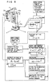
- Fig. 8 shows the processing procedure for such calibration.
- the microprocessor 41 reads out the rigidity transformation matrix [B] stored in the RAM 42 and executes the arithmetic operating process such that the matrix [B] is multiplied to the voltage value V detected from the force sensor 12 and the like. In this manner, the force Factually applied to the force sensor 12 can be calculated. For instance as shown in EP-A1-129245, published 27.12.84, it is possible to make the robot perform a predetermined work on the basis of the signal detected from the force sensor 12.
- the rigidity transformation matrix [B] can be derived due to the arithmetic logic operation by the robot itself equippped with the control unit without using a dedicated tool or the like, so that the invention presents the action and effect such that the calculation time and labor can be reduced. Namely, the work such that the force sensor is detached from the robot or the like can be eliminated.
- the force and moment are measured in the state whereby the bias value of the force sensor is always taken into account, the presence or absence of the variation in the bias value can be soon detected. At the same time, even if an external force enough to vary the bias value acts, they can be again measured without detaching the work and the like from the force sensor, so that a high degree of accuracy is derived and the measurement time can be reduced. Moreover, the transformation matrix of the force sensor which can cope with all of the forces and moments can be obtained. Also, efficient measurement can be performed by properly selecting the weight responsive to the kind of force sensor.
Landscapes
- Engineering & Computer Science (AREA)
- Physics & Mathematics (AREA)
- General Physics & Mathematics (AREA)
- Robotics (AREA)
- Mechanical Engineering (AREA)
- Human Computer Interaction (AREA)
- Force Measurement Appropriate To Specific Purposes (AREA)
- Manipulator (AREA)
- Buildings Adapted To Withstand Abnormal External Influences (AREA)
Description
- The present invention relates to detecting method of a force sensor for automatically detecting a transformation matrix indicative of the relationship between the strain voltage and the force (force and torque are referred to as a "force" as a general term) in a six degree of freedom force sensor (namely, which can detect three components of the force and three components of the torque) which is attached to a robot.
- A force sensor is attached to a robot and finds out the relation between the force and the strain voltage in the relevant portion. The relation between the strain voltage and the force is unconditionally determined and it is expressed by the following mathematical expression.

- As a conventional example of methods for obtaining the transformation matrix [B], there has been proposed US-A-4094192, "Method and Apparatus for Six Degree of Freedom Force Sensing".
- A measuring apparatus in this conventional example is shown in Fig. 1. A force sensor 2 is fixedly attached to a base 1. A cable 4 is attached to a moving portion 3 of the force sensor 2 and a
sash weight 5 depends from the end of the cable 4 through a pulley 6. The weight of the sash weight and the attaching direction of the cable 4 are changed by such an apparatus. Due to this, the data necessary for the transformation matrix is obtained and the transformation matrix is calculated. - Although this conventional example is an effective method of obtaining the transformation matrix, it has a problem such that a large amount of labor and a long time are needed. In addition, in the case where the force sensor is attached to a robot and the characteristic values of the force sensor are varied due to an impulse force or the like, the transformation matrix has to be calculated by removing the force sensor from the robot every time they are varied.
- As a further step according to Fig. 8 of JP-A-57-136133, a hand portion of a robot is replaced by a calibrated component detector and a load member to calibrate the component detector of the robot.
- Namely, this prior art according to JP-A-57-136133 requires a replacing operation, so that it seems to be difficult to calibrate said component detector to be calibrated accurately due to the error caused by the attaching operation of the calibrated component detector and the load member even if the detector has once been calibrated with high accuracy.
- It is an object of the present invention to provide a method for calibrating a transformation matrix of a force sensor in which the transformation matrix which is the characteristic value of the force sensor attached to a robot itself can be calibrated.
- This object is achieved with a calibration method as claimed.
- Dependent claim 2 is directed on a preferred embodiment of the method according to the invention.
- The present invention is made by paying an attention to the points such that the state whereby a robot is set into different postures by attaching a force sensor and standard works to the robot is equivalent to the state whereby many independent forces (forces and moments) are applied to the force sensor and that the postures and their coordinates can be simultaneously detected from the robot itself. Namely, an attention is paid to the point such that the transformation matrix can be automatically calibrated on the basis of the postures and coordinates which are detected from the robot itself by merely setting the robot into a few kinds of different postures by swinging the wrist on the basis of certain conditions in the state whereby the force sensor and the proper standard work are attached to the robot.
- On one hand, in the present invention, it is necessary to attach different standard works (weights) to a force sensor in case of calibrating the transformation matrix [B] with regard to the force sensor which can respond to four or more dimensions.
- In addition, with respect to the force sensor which can respond to n dimensions, the present invention has a feature such that (n+1) or more linear independent forces are applied and the transformation matrix [A] including a bias value is calibrated.
-
- Fig. 1 is a diagram showing a conventional example;
- Fig. 2 is a diagram showing one embodiment of the present invention;
- Fig. 3 is a diagram showing an arrangement example of a force sensor;
- Fig. 4 is a diagram showing the case where a standard work is attached;
- Fig. 5 is a diagram showing the case where another standard work is attached;
- Fig. 6 is a diagram showing the case where still another work is attached;
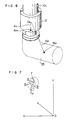
- Fig. 7 is a diagram showing the posture of the force sensor and the like according to the present invention;
- Fig. 8 is a flowchart showing a procedure for calculating the rigidity transformation matrix [B] of the force sensor of the present invention;
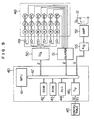
- Fig. 9 is a diagram showing a control unit and the like of a robot according to the present invention;
- Fig. 10 is a diagram showing a relational expression between the voltage value V and force F which are detected in the force sensor having a six-dimensional vector; and
- Fig. 11 is a diagram showing an expression showing the principle to calculate the rigidity transformation matrix [B] of the force sensor according to the present invention.
- The present invention will now be described hereinbelow with respect to an embodiment shown in the drawings.
- Fig. 2 is a diagram showing a robot to which a force sensor is attached. As a
robot 10 having six degrees of freedom, for example, there has been proposed in EP-A2-78522. Therobot 10 is equipped with aswivel pedestal 10a, an upper arm 10b and a forearm 11. Awrist 10c having three degrees of freedom is mounted at the end of the forearm 11. Aforce sensor 12 is attached between thewrist 10c and ahand portion 13. - The
force sensor 12 is a strain gauge and generates strain voltages corresponding to the forces regarding six degrees of freedom in response to the force applied to thehand portion 13. The term "force" denotes both of the force and the moment and this force is a six-dimensional vector. The coordinate axes (Ob―xb―yb―zb) of the base and the coordinate axes (Os―xs―ys―zs) of theforce sensor 12 are different as shown in Fig. 2. - An arrangement of the
force sensor 12 is shown in Fig. 3. Theforce sensor 12 comprises an external.member 21, aninternal member 23, andthin plate members 22. Theexternal member 21 is fixed to thewrist 10c and theinternal member 23 is fixed to thehand portion 13. Thethin plate members 22 couple theinternal member 23 with theexternal member 21. Strain gauges 24 are attached to portions of thethin plate members 22. - When a force is applied to the
hand portion 13 in such an arrangement, the force is propagated to theinternal member 23 coupled to thehand portion 13, causing the strain gauges 24 to be deformed through thecoupling plates 22. The voltages corresponding to those deformations are generated at output terminals of the strain gauges 24 and are detected. The relationship between the force and the strain voltage is unconditionally determined by properly setting the number, dimensions, and attaching positions of the thin plate portions, and the number and attaching positions of the strain gauges, and the like. Therefore, the force can be detected from the magnitude of the strain voltage. The relation between the force and the strain voltage is decided by the rigidity transformation matrix [B]. However, there is a large posssibility that the rigidity transformation matrix [B] is varied due to a time-dependent change or the impulse force applied to the hand portion after theforce sensor 12 was attached to the robot. Therefore, it is necessary to calibrate the rigidity transformation matrix [B] in the state whereby the force sensor was attached to the robot. - On one hand, as shown in Fig. 9, a
control unit 40 is connected to therobot 10 in order to allow the robot to perform a predetermined operation in response to a force signal detected from theforce sensor 12 and further in accordance with a program stored in thecontrol unit 40. - Practically speaking, as disclosed in EP―A1―129245, published 27.12.84, this robot is the
joint type robot 10 comprising: theswivel pedestal 10a which rotates around the vertical axis on the base; the upper arm 10b which rotates around the horizontal axis on theswivel pedestal 10a; the forearm 11 rotatably coupled with the end of the upper arm 10b; and thewrist 10c rotatably mounted at the end of the forearm 11 so as to have three degrees of freedom as illustrated in the diagram. Theforce sensor 12 is attached to the end of thewrist 10c of thejoint type robot 10. The force applied to the robot is detected by theforce sensor 12. The present position of the robot is detected by way of output signals from encoders PE or the like coupled with motors M or the like for driving therespective operating elements robot 10. In addition, tachogenerators TG or the like are coupled with the motors M such that the rotating speeds of the respective operating elements can be detected. Further, a proximity sensor or the like to detect the distance between thewrist 10c of the robot and an object may be attached to thewrist 10c. - In this manner, the
position 8 of the robot, the voltage V detected from theforce sensor 12, and the like are supplied to thecontrol unit 40 constituted by a microcomputer. Further, the instruction values such as the position xr, postures f, g, h, force Fe, weight of the weight, position of the center of gravity of the weight, weight of the hand portion, position of the center of gravity of the hand portion, internal weight of the force sensor, position of the center of gravity of the force sensor, instructions of predetermined points to form the operating path, and the like are inputted to thecontrol unit 40 from a control table 45 or the like. Practically speaking, thecontrol unit 40 is constituted by, for example: amicroprocessor 41; aRAM 42; aROM 43; anarithmetic logic unit 44; an interface circuit (I/F) 46 to connect thecontrol unit 40 with the control table 45; a D/A converter 50; acounter 51 to count the outputs from the encoders PE; an A/D converter 53 to convert an analog signal outputted from anamplifier 52 to a digital signal; and abus line 47 to connect the above-mentioned components. - Although the instruction values of the position Xr, force Fe and the like may be "0", in this case, the robot operates only by the force which is applied to the
hand portion 13. Namely, the passive mechanism is constituted. On the other hand, when no force is applied to the hand portion 13 (or thesensor 12 or the like is not attached to the hand portion 13) and only the instruction values of the position Xr, forceF c, and the like are given, the movement is determined by these instruction values. - In any of those cases, the
control unit 40 generates an instruction value of the joint angular velocity θ of the robot toservo amplifiers 49, thereby making therobot 10 operative. - For the coordinate conversion by the
control unit 40, the signals from the encoders PE of the respective joints of the robot are counted by thecounter 51 and thepresent position 8 is received and the coordinate conversion from thejoint angle 8 into the orthogonal coordinates x of the hand system is performed. Actually, this coordinate conversion is performed by thearithmetic logic unit 44 in response to a command from themicroprocessor 41. In addition, the external force F applied to the robot is detected by theforce sensor 12. Thecontrol unit 40 receives the external force F through the A/D converter 53 as a voltage V of the strain gauge constituting theforce sensor 12. Theforce calculating section ALU 44 in response to a command from themicroprocessor 41. Next, in the case where the weight of an object which is grasped by thehand portion 13 and the hand is large, the values which are applied to theforce sensor 12 differ in dependence on the posture of the hand. Therefore, the rigidity transformation matrix [B] is calibrated on the basis of the posture andposition 8 of thehand portion 13, thereby eliminating the influence due to the posture of the hand and calculating the force F actually applied to the robot. - The value calculated in this manner is F and given to the
main control section hand portion 13 operates is calculated by the main control section. Next, since v is the value in the coordinate system fixed to the hand, this value is converted to the velocity vo in the coordinate system of the base by way of the coordinate conversion. - Thereafter, the angular velocity θ of each axis of the robot is calculated by the joint angle calculating section on the basis of the velocity
V 0 in the orthogonal coordinate system. In this case,
angle 8 of the robot). Theservo amplifiers 49 operate on the basis of the angular velocity θ, so that the motors M for the respective joints of the robot are made operative. - As well as the force F from the robot and the position x of the robot, the instruction values Fe and Xr of the force and position are also inputted to the main control section, and the velocity v of the hand portion is outputted.
- The force F applied to the
force sensor 12 has to be calculated from the voltage value V detected from theforce sensor 12. It is necessary to preliminarily calibrate and determine the rigidity transformation matrix [B] for calculation of the force F. A method of calibrating the transformation matrix [B] of the force sensor, which is a feature of the present invention, in the state whereby the force sensor was attached to the robot in this manner will then be practically described hereinbelow. - Strictly speaking, the strain voltage V of the
force sensor 12 can be specified by
V d is a voltage generated when no force is applied to the force sensor 12 (the internal weight is also regarded as a force). This voltage Vd is an n-dimensional vector. Vo is a voltage generated when a force was actually applied to the force sensor 12 (internal weight is regarded as a force). This voltage Vo is also an n-dimensional vector. In this case, n≧6. - The force F is a force applied to the
force sensor 12 and is considered in the sensor coordinate system. This force F consists of a force and a moment and is a six-dimensional vector. - Further, it is assumed that there is the linear relation between the force F and the strain voltage V. Thus,

- The internal weight Win and the position
d in of center of gravity of the internal weight (this position is a value expressed by the sensor coordinate system (hereinafter, referred to as an S system) indicated by Os―xs―ys―zs shown in Fig. 2) can be preliminarily obtained using the design drawing or the like; therefore, they may be considered as known values which can be inputted from the control table 45. - Although it is necessary to obtain the strain gauge voltage
V d when the internal weight Win was removed, it cannot be removed because the internal weight Win is a part of the sensor. Therefore, the following method is adopted. - The
force sensor 12 is attached to the end of the forearm 11 of the robot. Further, nothing is attached to the end of theforce sensor 12. - The
robot 10 is controlled by inputting the positions x, y, z and positions f, g, h, and the like from the control table 45 shown in Fig. 9 in a manner such that the coordinate axis Zs of the sensor coordinate system faces downward, namely, in the direction of the gravity. The strain voltage is measured by theforce sensor 12 under the condition whereby the coordinate axis Zs faces in the direction of the gravity. This strain voltage is set toV dow. - Next, the coordinate axis Zs of the sensor coordinate system is set into the upward posture and the strain voltage is measured by the
force sensor 12 in this posture. This strain voltage is set to Vup. - From
V dow and Vup, the voltage Vd is derived from the following equation.
- The foregoing terms "downward" and "upward" are based on the concept such that the posture is reversed with regard to the direction of the gravity. Due to this, the force and moment which are caused due to the internal weight applied to the force sensor are set off and become zero since their positive and negative signs are inverted. It is now assumed that the unit vector in the direction of the gravity in case of the downward posture is Udow (S system indication) and the unit vector in the direction of the gravity in case of the upward posture is
U up (S system indication). Those unit vectors are considered in the sensor coordinate system. In this case,
-


- Therefore, equation (4) is correct and the voltage Vd is derived from equation (4).
- In place of the
hand portion 13 shown in Fig. 2, a standard work is attached to theforce sensor 12. Fig. 4 shows a perspective view in the case where a standard work is attached. It is assumed that astandard work 31 has the weight Wst and the position of the center of gravity in the sensor coordinate system is dst. These Wst andd st can be together inputted from the control table 45 and are known values. - Since the
standard work 31 of Wst is added to the internal weight Win, the total weight W of them becomes -

d of the center of gravity (S system indication) becomes -

- As shown in Fig. 2, it is now assumed that the unit vector indicative of the direction of the gravity is Ub in the coordinate system (Ob―xb―yb―zb) of the base of the
wrist 10c. This Us is a known value which can be obtained on the basis of theposition 8 which is detected from the encoder PE. The unit vector indicative of the direction of the center of gravity in the sensor coordinate system assumes us. The unit vectors in the directions of the respective coordinate axes in the sensor coordinate system assume f, 9 and h. The following equation is satisfied under these conditions.
- Assuming that the force and moment are together F in consideration of both of the internal weight of the force sensor and the weight of the standard work,

f is a translational force acting on the force sensor in the sensor coordinate system and m denotes a moment around the origin in the sensor coordinate system.

- Six elements of the vector F denote the components of the force in the x, y and z axes and the components of the moment in the x, y and z axes.
- On one hand, the strain voltage V is obtained from equation (2). Namely, the actual strain voltage Vo is derived and the voltage Vd is subtracted from this Vo, so that the value of V can be derived.
- The process mentioned in the above item (3) is one example of measurement under the condition whereby only one posture is set and one standard work is attached. In the actual situation, measurement is performed under the respective conditions whereby the posture of the robot is varied and the standard work is changed (the weight and the position of the center of gravity are changed) in response to commands from the control table 45.
- By respectively executing the measurement under the conditions of (posture a1, work b1), (posture a2, work b2), ..., and (posture am, work bm), the following equations are derived.


F 1,F 2, ...,F m] is a matrix of six rows and m columns, [B] is a matrix of six rows and n columns, and [V 1,V 2 ...,V m] is a matrix of n rows and m columns, wherein m≧6 and n≧6. On one hand, it is assumed that at least six independent vectors are included inF 1, F2, ..., Fm. When [F 1,F 2 ...,F m] is substituted by [F] and (V 1, V2,..., Vm] is substituted by [V], equation (15) will become
-


- The foregoing embodiment relates to a method by way of sets consisting of different postures and work (for example, six sets). However, there is also another method.
- Namely, it is a method whereby two kinds of works whose positions of the centers of gravity differ as shown in Figs. 6 and 7, for instance, works 34 and 35 are used, and three or more kinds of different postures are set with respect to one work, thereby obtaining the forces F1, F2, ...,
F i (where, 1≧6) which are applied to the force sensor. As will be explained hereinafter, at least six independent forces are included in those forces F1 toF 1. By substitutingF 1 to F, for equation (15) and substituting the voltages V1, V2, ...,V i of the corresponding strain gauges forV 1, V2, ..., Vm, the transformation matrix [B] can be derived from equation (17). - In Fig. 8, the
robot 10 is used to change the posture of the force sensor. By allowing theweight 14 in which the position of the center of gravity and the weight are known to depend from thehand portion 13 in which the position of the center of gravity and the weight are known, the force independent to theforce sensor 12 is applied to the end of theforce sensor 12 attached to thewrist 10c of therobot 10. The direction opposite to the direction of the gravity of the earth is the z axis and the coordinate axes of x and y are arbitrarily determined. Then, the postures of theforce sensor 12 expressed by those fundamental coordinates are represented by the f, 9 andh vectors. These f, g and h are direction cosines in the case where the coordinate axes of the sensor system are considered in the fundamental coordinate system. Now, assuming that the position vector until the weight 14 (including the hand portion 13) in the sensor system is d and the weight is W as shown in Fig. 7, the translational force f and the moment m which act on theforce sensor 12 due to theweight 14 are expressed by the following equations.

-


- It will be obviously appreciated from equation (10) or (19), or equation (11) or (20) that the values off and m can be sufficiently varied by changing the posture of the force sensor due to a single work. However, only up to three sets of forces and moments which can be applied to the force sensor in this way are linear and independent. It is now assumed that the q vector is a six-dimensional vector consisting of the vector f of the translational force and the vector m of the moment. This vector denotes the column component vector F fo the matrix [F].

- No problem will be caused if six q vectors are independent; however, when the values of d and Ware constant, only three sets of linear and independent forces are provided. An attention is first paid to the translational force which is a component of the vector q. Unless
f 1 and f2 and f3 exist on the same plane,f 1, f2 and f3 are obviously linear and independent and in this case, q1, q2 and q3 are also linear and independent. Another q, is then be examined. This qi is expressed as follows.
f 1,f 2 andf 3 are linear and independent,f i apparently becomes
f i is expressed by the sum of f1, f2 and f3. Therefore,f i becomes linear and dependent. Next,m i is examined. - From equation (13) or (20),


q i is expressed by the sum of q1 +q2+q3 and is linear and dependent. It will be understood from the above-mentioned point that only three sets of linear and independent forces are derived in the case where W and U are constant. It will be understood from equation (12) or (19) or equation (13) or (20) that even if W is changed, q, is merely increased by constant times; therefore, to obtain other independent forces, it is necessary to vary the position vectord until the position of the center of gravity. Consequently, to apply four or more sets of linear independent forces, it is sufficient that the weight is replaced by another weight in which the position of the center of gravity differs. The foregoing points are summarized as follows. In the force sensor which can sense three or less kinds of forces, it is sufficient to apply up to three sets of independent forces; so that one weight is needed. While, in the force sensor which can sense four or more kinds of forces, it is necessary to apply four or more independent forces; therefore, two kinds of weights are needed. - The foregoing modification relates to an example. The number of kinds of works, the number of works, the number of kinds of postures, and the number of postures may be arbitrarily selected if they satisfy the condition such that at least six independent forces F are included. Therefore, a proper combination may be selected in accordance with each requirement of the conditions when the transformation matrix [B] is selected, for example,
- (a) the change in kinds of works is made as little as possible;
- (b) the work is set into the posture as near as the downward posture as possible;
- (c) a degree of accuracy of the [B] is made as high as possible; and the like.
- On the other hand, the Ob'―xb'―yb'―zb' coordinate system was defined for convenience of description of the posture; however, any other coordinate systems may be used as necessary.
- As another feature of the present invention, there is a method whereby the transformation matrix [A] having the offset force and moment as one column component in the transformation matrix is used.
- As shown in Fig. 8, if the data which is outputted from the force sensor when an arbitrary force
F i=(fxi, fyi, fzl, mxi, myi, mzi, 1) was applied to the force sensor assumesV i=(v1i, v2i, V31, v4i, V51, v6i, 1), the matrix [F] in which the vectors of the force are the column components and the matrix [V] in which the force sensor data are the column components are derived. Namely,


-

- The necessary and sufficient condition in the case where the matrix [F] has the inverse matrix [F]-' or affine inverse matrix [F]* is that the column components F, of the matrix [F] are linear and independent. In other words, in the force sensor which can sense n kinds of forces (1≦n≦6), it will be appreciated that n or more column components F have to be linear and independent. Thus, in this embodiment, since n equals 6, it is necessary to apply the column vectors of at least six linear independent forces to the force sensor. However, since the extended rigidity matrix [A] including the bias value is 7x7, one or more column vectors of the linear independent force are further needed. The foregoing points can be summarized as follows. In the force sensor which can sense n kinds of forces (1≦n≦6), it is necessary to apply at least n sets of linear independent forces to the force sensor and in order to obtain the rigidity matrix [A] including the bias value, it is the necessary and sufficient condition to apply (n+1) or more sets of linear independent forces to the force sensor.
- Namely, this embodiment intends to obtain the transformation matrix [A] of which the transformation matrix [B] shown in Fig. 10 was extended to seven rows and (n+1) columns from six rows and n columns. Fig. 11 shows one example of such an extended transformation matrix [A].
- As mentioned previously, the strain voltage V is derived by subtracting the offset voltage Vd previously obtained from the voltage Vo as shown in equation (2) and this data is used as the data of the matrix [V] of the voltage. However, by obtaining the matrix [A], which is another feature of the present invention, there is no need to preliminarily obtain the offset voltage Vd. For example, the matrix [A] can be obtained by the following method. Namely, the column components F, of the matrix [F] of equation (15) assume


- As described above, if the total number of measurement times is seven or more with regard to the
force sensor 12 having a six-dimensional vector, the rigidity transformation matrix [B] in consideration of the bias value can be extremely simply and promptly calculated in the state whereby theforce sensor 12 is attached to thewrist 10c of the robot without removing thehand portion 13. - In any cases, the
robot 10 is provided with thecontrol unit 40 and the like as mentioned above. Further, the driving motors M and encoders PE are attached to therobot 10 and the position and posture of theforce sensor 12 of the robot can be detected from the encoders PE. Moreover, theforce sensor 12 of the robot can be set into an arbitrary position and posture by inputting a command to thecontrol unit 40 from the control table 45. Also, it is possible to input the known data (for example, the weights of theforce sensor 12,hand portion 13, andweights force sensor 12,hand portion 13, andweights arithmetic logic unit 44 of thecontrol unit 40. Therefore, themicroprocessor 41 reads out the program stored in theROM 43 and sets the robot into various postures in response to commands from the control table 45. At the same time, the weight is changed and the weights and the positions of the centers of gravity of the weights and the like are given from the control table 45. Predetermined arithmetic logic operations are performed in theALU 44 on the basis of the voltage value V detected from theforce sensor 12 under the respective conditions, thereby calibrating the rigidity transformation matrix [B] of the force sensor. Then, this calibrated matrix is stored into theRAM 42. Fig. 8 shows the processing procedure for such calibration. After that, themicroprocessor 41 reads out the rigidity transformation matrix [B] stored in theRAM 42 and executes the arithmetic operating process such that the matrix [B] is multiplied to the voltage value V detected from theforce sensor 12 and the like. In this manner, the force Factually applied to theforce sensor 12 can be calculated. For instance as shown in EP-A1-129245, published 27.12.84, it is possible to make the robot perform a predetermined work on the basis of the signal detected from theforce sensor 12. - As described above, according to the present invention, the rigidity transformation matrix [B] can be derived due to the arithmetic logic operation by the robot itself equippped with the control unit without using a dedicated tool or the like, so that the invention presents the action and effect such that the calculation time and labor can be reduced. Namely, the work such that the force sensor is detached from the robot or the like can be eliminated.
- Further, according to the present invention, since the force and moment are measured in the state whereby the bias value of the force sensor is always taken into account, the presence or absence of the variation in the bias value can be soon detected. At the same time, even if an external force enough to vary the bias value acts, they can be again measured without detaching the work and the like from the force sensor, so that a high degree of accuracy is derived and the measurement time can be reduced. Moreover, the transformation matrix of the force sensor which can cope with all of the forces and moments can be obtained. Also, efficient measurement can be performed by properly selecting the weight responsive to the kind of force sensor.
Claims (2)
Applications Claiming Priority (4)
| Application Number | Priority Date | Filing Date | Title |
|---|---|---|---|
| JP210435/84 | 1984-10-09 | ||
| JP59210435A JPS6190895A (en) | 1984-10-09 | 1984-10-09 | Transform-matrix detection method of force sensor |
| JP60120416A JPH0629817B2 (en) | 1985-06-05 | 1985-06-05 | How to measure force / moment |
| JP120416/85 | 1985-06-05 |
Publications (3)
| Publication Number | Publication Date |
|---|---|
| EP0177919A2 EP0177919A2 (en) | 1986-04-16 |
| EP0177919A3 EP0177919A3 (en) | 1987-02-04 |
| EP0177919B1 true EP0177919B1 (en) | 1989-10-04 |
Family
ID=26458004
Family Applications (1)
| Application Number | Title | Priority Date | Filing Date |
|---|---|---|---|
| EP85112676A Expired EP0177919B1 (en) | 1984-10-09 | 1985-10-07 | Method for calibrating transformation matrix of a force sensor |
Country Status (4)
| Country | Link |
|---|---|
| US (1) | US4620436A (en) |
| EP (1) | EP0177919B1 (en) |
| KR (1) | KR890000736B1 (en) |
| DE (1) | DE3573473D1 (en) |
Cited By (2)
| Publication number | Priority date | Publication date | Assignee | Title |
|---|---|---|---|---|
| GB2241338A (en) * | 1990-02-27 | 1991-08-28 | Prima Misure Spa | Metrologically testing and self-correcting a measurement machine for geometric detection errors |
| EP0742428A1 (en) * | 1995-05-11 | 1996-11-13 | Nikon Corporation | Calibrating a multi-axes dynamics detector especially mounted and with a camera to contact manual blurring |
Families Citing this family (40)
| Publication number | Priority date | Publication date | Assignee | Title |
|---|---|---|---|---|
| US4982611A (en) * | 1988-05-24 | 1991-01-08 | Wisconsin Alumni Research Foundation | Multiple-degree-of-freedom sensor tip for a robotic gripper |
| US5261266A (en) * | 1990-01-24 | 1993-11-16 | Wisconsin Alumni Research Foundation | Sensor tip for a robotic gripper and method of manufacture |
| US5010773A (en) * | 1990-01-24 | 1991-04-30 | Wisconsin Alumni Research Foundation | Sensor tip for a robotic gripper and method of manufacture |
| JP2521830B2 (en) * | 1990-02-14 | 1996-08-07 | 川崎重工業株式会社 | Control method and apparatus for industrial robot |
| US5331770A (en) * | 1991-07-26 | 1994-07-26 | Hitachi, Ltd. | Method for scraping off excessive portion of workpiece |
| JP3167404B2 (en) * | 1992-02-26 | 2001-05-21 | 本田技研工業株式会社 | Robot joint drive controller |
| US5606516A (en) * | 1995-08-07 | 1997-02-25 | Fairbanks Scales Inc. | Digitally compensated hydraulic scale system |
| JP3053606B2 (en) * | 1998-02-23 | 2000-06-19 | ファナック株式会社 | Method of calibrating force sensor mounted on robot and robot |
| US6629446B2 (en) * | 2001-01-08 | 2003-10-07 | The United States Of America As Represented By The Administrator Of The National Aeronautics And Space Administration | Single vector calibration system for multi-axis load cells and method for calibrating a multi-axis load cell |
| JP2002239963A (en) * | 2001-02-21 | 2002-08-28 | Sony Corp | Robot device and its action control method, program, and recoding medium of robot device |
| JP4485887B2 (en) * | 2004-09-17 | 2010-06-23 | 本田技研工業株式会社 | Force sensor abnormality detection device for legged mobile robot |
| JP3977369B2 (en) * | 2004-10-01 | 2007-09-19 | ファナック株式会社 | Robot program generation device and analysis device |
| CN100561157C (en) * | 2004-12-17 | 2009-11-18 | 鸿富锦精密工业(深圳)有限公司 | dynamometer automatic correction system and method |
| CN1328018C (en) * | 2005-01-05 | 2007-07-25 | 天津大学 | Main operation hand with clamping force sensation |
| US8496647B2 (en) | 2007-12-18 | 2013-07-30 | Intuitive Surgical Operations, Inc. | Ribbed force sensor |
| US7752920B2 (en) | 2005-12-30 | 2010-07-13 | Intuitive Surgical Operations, Inc. | Modular force sensor |
| US7930065B2 (en) * | 2005-12-30 | 2011-04-19 | Intuitive Surgical Operations, Inc. | Robotic surgery system including position sensors using fiber bragg gratings |
| WO2007120329A2 (en) * | 2005-12-30 | 2007-10-25 | Intuitive Surgical, Inc. | Modular force sensor |
| DE102006004283B4 (en) * | 2006-01-31 | 2009-02-05 | Deutsches Zentrum für Luft- und Raumfahrt e.V. | Calibration device and calibration method for calibrating force-moment sensors |
| US8561473B2 (en) | 2007-12-18 | 2013-10-22 | Intuitive Surgical Operations, Inc. | Force sensor temperature compensation |
| US8412378B2 (en) | 2009-12-02 | 2013-04-02 | GM Global Technology Operations LLC | In-vivo tension calibration in tendon-driven manipulators |
| JP5550468B2 (en) * | 2010-06-30 | 2014-07-16 | キヤノン株式会社 | Force sensor calibration method |
| JP5191521B2 (en) | 2010-10-05 | 2013-05-08 | 株式会社神戸製鋼所 | Calibration method of multi-component force measuring spindle unit used in tire testing machine |
| TWI465705B (en) * | 2011-01-03 | 2014-12-21 | First Tools Ind Co Ltd | An automatic checking method and the device therefore |
| US9052250B1 (en) | 2012-05-04 | 2015-06-09 | The United States Of America As Represented By The Administrator Of The National Aeronautics And Space Administration | Method of calibrating a force balance |
| JP6051678B2 (en) | 2012-08-22 | 2016-12-27 | セイコーエプソン株式会社 | Sensor device, sensor module, force detection device and robot |
| US8943902B2 (en) * | 2012-10-05 | 2015-02-03 | Harris Corporation | Force and torque sensors |
| CN103698086B (en) * | 2013-12-15 | 2015-12-30 | 中国航空工业集团公司哈尔滨空气动力研究所 | Solve the method that polynary strain-type force measuring sensors is located on calibrating table |
| US20160033317A1 (en) * | 2014-08-04 | 2016-02-04 | TaKaDu Ltd. | System and method for assessing sensors' reliability |
| US9993309B2 (en) * | 2015-02-03 | 2018-06-12 | Stryker Corporation | Force/torque transducer and method of operating the same |
| US9844872B1 (en) | 2015-07-13 | 2017-12-19 | X Development Llc | Determining sensor parameters and model parameters of a robot |
| JP7086531B2 (en) * | 2017-05-18 | 2022-06-20 | キヤノン株式会社 | Robot hand, robot device, robot hand control method, article manufacturing method, control program and recording medium |
| CN108042162B (en) * | 2017-12-21 | 2020-06-16 | 微创(上海)医疗机器人有限公司 | Surgical robot system and surgical instrument thereof |
| CN110553766A (en) * | 2018-05-30 | 2019-12-10 | 浙江清华柔性电子技术研究院 | Force sensor and method for manufacturing the same |
| CN109985846B (en) * | 2019-01-11 | 2022-07-08 | 贵州电网有限责任公司 | Laser radar calibration method for live-line water washing robot of transformer substation |
| WO2020170770A1 (en) | 2019-02-18 | 2020-08-27 | XELA・Robotics株式会社 | Detection device and sensor calibration method |
| CN111351615B (en) * | 2020-03-25 | 2021-07-20 | 东南大学 | High-precision small-sized on-orbit calibration device and method for spatial station mechanical arm six-dimensional force sensor |
| CN113916441A (en) * | 2020-07-08 | 2022-01-11 | 北京航飞科技开发研究所 | Calibration device and calibration method of force sensor |
| CN112857667B (en) * | 2021-03-15 | 2022-10-14 | 合肥工业大学 | Hybrid excitation dynamic calibration method of strain type six-dimensional force sensor |
| CN115805593B (en) * | 2022-12-22 | 2023-11-28 | 苏州艾利特机器人有限公司 | Force sensor installation information determining method, device, equipment and medium |
Citations (1)
| Publication number | Priority date | Publication date | Assignee | Title |
|---|---|---|---|---|
| JPS57136133A (en) * | 1981-02-18 | 1982-08-23 | Hitachi Ltd | Calibrating method for component detector |
Family Cites Families (4)
| Publication number | Priority date | Publication date | Assignee | Title |
|---|---|---|---|---|
| US4094192A (en) * | 1976-09-20 | 1978-06-13 | The Charles Stark Draper Laboratory, Inc. | Method and apparatus for six degree of freedom force sensing |
| US4132318A (en) * | 1976-12-30 | 1979-01-02 | International Business Machines Corporation | Asymmetric six-degree-of-freedom force-transducer system for a computer-controlled manipulator system |
| JPS57207908A (en) * | 1981-06-17 | 1982-12-20 | Hitachi Ltd | Robot controller |
| US4547858A (en) * | 1983-06-13 | 1985-10-15 | Allied Corporation | Dynamic control for manipulator |
-
1985
- 1985-10-04 US US06/784,502 patent/US4620436A/en not_active Expired - Lifetime
- 1985-10-07 KR KR1019850007359A patent/KR890000736B1/en not_active IP Right Cessation
- 1985-10-07 DE DE8585112676T patent/DE3573473D1/en not_active Expired
- 1985-10-07 EP EP85112676A patent/EP0177919B1/en not_active Expired
Patent Citations (1)
| Publication number | Priority date | Publication date | Assignee | Title |
|---|---|---|---|---|
| JPS57136133A (en) * | 1981-02-18 | 1982-08-23 | Hitachi Ltd | Calibrating method for component detector |
Cited By (3)
| Publication number | Priority date | Publication date | Assignee | Title |
|---|---|---|---|---|
| GB2241338A (en) * | 1990-02-27 | 1991-08-28 | Prima Misure Spa | Metrologically testing and self-correcting a measurement machine for geometric detection errors |
| EP0742428A1 (en) * | 1995-05-11 | 1996-11-13 | Nikon Corporation | Calibrating a multi-axes dynamics detector especially mounted and with a camera to contact manual blurring |
| US5686665A (en) * | 1995-05-11 | 1997-11-11 | Nikon Corporation | Dynamic amount detector, dynamic amount detecting method, and camera with dynamic amount detector |
Also Published As
| Publication number | Publication date |
|---|---|
| US4620436A (en) | 1986-11-04 |
| DE3573473D1 (en) | 1989-11-09 |
| EP0177919A2 (en) | 1986-04-16 |
| KR860003090A (en) | 1986-05-19 |
| EP0177919A3 (en) | 1987-02-04 |
| KR890000736B1 (en) | 1989-04-03 |
Similar Documents
| Publication | Publication Date | Title |
|---|---|---|
| EP0177919B1 (en) | Method for calibrating transformation matrix of a force sensor | |
| US4906907A (en) | Robot system | |
| CN111618857B (en) | Multi-load self-adaptive gravity compensation method for mechanical arm | |
| US6382012B2 (en) | Method for calibrating force sensor mounted on robot, and robot | |
| US4132318A (en) | Asymmetric six-degree-of-freedom force-transducer system for a computer-controlled manipulator system | |
| JP3792274B2 (en) | Six-axis force sensor using multiple shear strain gauges | |
| US6532830B1 (en) | High payload six-axis load sensor | |
| EP0358765B1 (en) | Automatic setting of tool tip point | |
| EP0151417A1 (en) | Method for correcting systems of coordinates in a robot having visual sensor device and apparatus therefor | |
| US20220088804A1 (en) | Method for determining a weight and a center of gravity of a robot manipulator load | |
| US5357424A (en) | Dynamic model parameter identification system | |
| EP0519081A1 (en) | Method of correcting deflection of robot | |
| Shimano et al. | On force sensing information and its use in controlling manipulators | |
| JPH07205075A (en) | Weight compensation method of end effector at force control robot | |
| JP2003050171A (en) | Method and apparatus for measuring multi-component force | |
| JPH06304893A (en) | Calibration system for positioning mechanism | |
| JPH0433006A (en) | Control method for robot system | |
| JPH0690104B2 (en) | Method and apparatus for calibrating the transformation matrix of a force sensor | |
| SU974155A1 (en) | Force and moment vector pickup | |
| Moreira et al. | First steps towards an open control architecture for a PUMA 560 | |
| KR0138568B1 (en) | Force/moment maesuring device | |
| Nilsson et al. | Combining a stable 2-D vision camera and an ultrasonic range detector for 3-D position estimation | |
| JP2520324B2 (en) | Automatic correction method for robot constants | |
| JP3196145B2 (en) | Contact point and contact normal detection method for machining / assembly equipment | |
| JPH0629817B2 (en) | How to measure force / moment |
Legal Events
| Date | Code | Title | Description |
|---|---|---|---|
| PUAI | Public reference made under article 153(3) epc to a published international application that has entered the european phase |
Free format text: ORIGINAL CODE: 0009012 |
|
| AK | Designated contracting states |
Kind code of ref document: A2 Designated state(s): DE FR GB |
|
| PUAL | Search report despatched |
Free format text: ORIGINAL CODE: 0009013 |
|
| AK | Designated contracting states |
Kind code of ref document: A3 Designated state(s): DE FR GB |
|
| 17P | Request for examination filed |
Effective date: 19870206 |
|
| 17Q | First examination report despatched |
Effective date: 19880224 |
|
| GRAA | (expected) grant |
Free format text: ORIGINAL CODE: 0009210 |
|
| AK | Designated contracting states |
Kind code of ref document: B1 Designated state(s): DE FR GB |
|
| REF | Corresponds to: |
Ref document number: 3573473 Country of ref document: DE Date of ref document: 19891109 |
|
| ET | Fr: translation filed | ||
| PLBE | No opposition filed within time limit |
Free format text: ORIGINAL CODE: 0009261 |
|
| STAA | Information on the status of an ep patent application or granted ep patent |
Free format text: STATUS: NO OPPOSITION FILED WITHIN TIME LIMIT |
|
| 26N | No opposition filed | ||
| REG | Reference to a national code |
Ref country code: GB Ref legal event code: IF02 |
|
| PGFP | Annual fee paid to national office [announced via postgrant information from national office to epo] |
Ref country code: FR Payment date: 20040921 Year of fee payment: 20 |
|
| PGFP | Annual fee paid to national office [announced via postgrant information from national office to epo] |
Ref country code: GB Payment date: 20040923 Year of fee payment: 20 |
|
| PGFP | Annual fee paid to national office [announced via postgrant information from national office to epo] |
Ref country code: DE Payment date: 20041206 Year of fee payment: 20 |
|
| PG25 | Lapsed in a contracting state [announced via postgrant information from national office to epo] |
Ref country code: GB Free format text: LAPSE BECAUSE OF EXPIRATION OF PROTECTION Effective date: 20051006 |
|
| REG | Reference to a national code |
Ref country code: GB Ref legal event code: PE20 |