EP0177383B1 - Broadband omnidirectional elastic wave transducer and method of manufacturing it - Google Patents
Broadband omnidirectional elastic wave transducer and method of manufacturing it Download PDFInfo
- Publication number
- EP0177383B1 EP0177383B1 EP85401673A EP85401673A EP0177383B1 EP 0177383 B1 EP0177383 B1 EP 0177383B1 EP 85401673 A EP85401673 A EP 85401673A EP 85401673 A EP85401673 A EP 85401673A EP 0177383 B1 EP0177383 B1 EP 0177383B1
- Authority
- EP
- European Patent Office
- Prior art keywords
- diaphragm
- spherical
- magnetostrictive
- transducer
- magnetostrictive material
- Prior art date
- Legal status (The legal status is an assumption and is not a legal conclusion. Google has not performed a legal analysis and makes no representation as to the accuracy of the status listed.)
- Expired - Lifetime
Links
Images


Classifications
-
- H—ELECTRICITY
- H04—ELECTRIC COMMUNICATION TECHNIQUE
- H04R—LOUDSPEAKERS, MICROPHONES, GRAMOPHONE PICK-UPS OR LIKE ACOUSTIC ELECTROMECHANICAL TRANSDUCERS; DEAF-AID SETS; PUBLIC ADDRESS SYSTEMS
- H04R15/00—Magnetostrictive transducers
-
- G—PHYSICS
- G01—MEASURING; TESTING
- G01H—MEASUREMENT OF MECHANICAL VIBRATIONS OR ULTRASONIC, SONIC OR INFRASONIC WAVES
- G01H11/00—Measuring mechanical vibrations or ultrasonic, sonic or infrasonic waves by detecting changes in electric or magnetic properties
- G01H11/02—Measuring mechanical vibrations or ultrasonic, sonic or infrasonic waves by detecting changes in electric or magnetic properties by magnetic means, e.g. reluctance
- G01H11/04—Measuring mechanical vibrations or ultrasonic, sonic or infrasonic waves by detecting changes in electric or magnetic properties by magnetic means, e.g. reluctance using magnetostrictive devices
Definitions
- the present invention relates to an omnidirectional transducer of elastic waves with a large passband.
- elastic waves is meant a pressure wave propagating in a liquid or in a gas.
- an elastic wave is often called an acoustic wave.
- the transducer can be used in transmission, and it then converts an electrical signal to an elastic wave, or in reception, and it then converts an elastic wave in an electrical signal.
- the transducer of the invention is suitable in particular for the transmission of sound and ultrasonic waves.
- the submarine transmission of high frequency elastic signals constitutes a privileged field of application of the invention.
- the transducer can be used as a hydrophone in both receiver and transmitter.
- the wide bandwidth of this transducer allows the transmission of high frequency signals such as for example television signals specially adapted for transmission in water (bandwidth of about 200 kHz), speech signals or any other signals of information.
- Another preferred field of application of the invention is high-fidelity sound reproduction.
- the transducer used in transmission achieves high-performance loudspeakers with wide bandwidth.
- Magnetostriction is the property for certain bodies to undergo a geometric modification (contraction, dilation, bending, torsion, ...) when they are subjected to the influence of a magnetic field.
- Metal alloys and in particular ferromagnetic compounds are magnetostrictive materials.
- the transducer mainly comprises a magnetostrictive bar arranged in a solenoid.
- a magnetic field is created in the axis of the solenoid which expands or contracts the magnetostrictive rod depending on the nature of the magnetostrictive material used. This creates, at each of the ends of the magnetostrictive bar, an elastic wave which propagates in a direction substantially parallel to the axis of the magnetostrictive bar.
- Patent EP-A-0 063 094 or also FR-A-2 503 516 entitled "omnidirectional loudspeaker for the acute frequencies of the sound spectrum” describes an electroacoustic transducer usable in air which authorizes the production of an elastic wave substantially omnidirectional from linear expansion or linear contraction depending on the material used, of a magnetostrictive bar.
- FIG. 1 shows an embodiment of a loudspeaker according to the teaching of this patent.
- This loudspeaker essentially comprises two rigid hemispheres 2 and 4 connected to each other by an elastic annular seal 6, to which they can be fixed by gluing, so as to form a pulsating sphere, and a control element 8 disposed inside the sphere and rigidly connected to hemispheres 2 and 4.
- the control element 8 has an elongated shape and can undergo a variation in length in response to an electrical signal to be converted into an elastic wave.
- This control element is oriented inside the sphere in such a way that the forces resulting from these length variations are transmitted to the hemispheres 2 and 4 in directions perpendicular to the connection plane of said hemispheres.
- This control element 8 is preferably less than the diameter of the sphere and it is then connected to the hemispheres 2 and 4 by rigid transmission parts 10 and 12 which are perpendicularly supported on the hemispheres 2 and 4 at places sufficiently distant from the region of their peaks so that each of said hemispheres moves or vibrates in one piece, in response to variations in length of the control element 8.
- These transmission parts have substantially the shape of a spherical cap.
- the control element 8 consists of a bar 14, of circular or square section, made of a magnetostrictive material, around which is an induction coil 16.
- the electrical signal to be converted into an elastic wave is applied to the ends of the coil 16 by two electrical conductors 18 and 20 which pass through an opening formed in the annular seal 6.
- the transmission parts 10 and 12 make it possible to convert the linear expansion of the magnetostrictive bar 14 into a displacement of each of the two hemispheres 2 and 4.
- the elastic wave produced is therefore substantially omnidirectional.
- the wave produced cannot be perfectly omnidirectional. This is partly due to the presence of the elastic annular seal 6 which connects the two hemispheres and which therefore prohibits emitting sion of the sound wave in the plane, and this is also due to the fact that the transmission parts do not modify the linear character of the force transmitted. It is therefore not exactly a pulsating sphere, that is to say having a variable radius but identical at each point at a given instant, but simply two hemispheres having simultaneously a linear movement of the same direction and of opposite. This is also the case of the loudspeaker described in patent EP-A-0 063 094.
- the object of the invention is to remedy the drawbacks of known devices, in particular their absence of real omnidirectionality.
- the membrane of the transducer of the invention can also be in the form of an unclosed surface; in the case of a hemispherical shape for example, the transducer is omnidirectional in a half-plane of space.
- the membrane is equipped with means for equalizing its internal and external pressures. This is particularly important in the case for example where it is desired to use the transducer underwater at variable depths.
- Internal and external pressure equalization can be achieved simply by drilling at least one small orifice in the membrane.
- the pressure on the external face of the membrane can also be compensated for by filling the internal volume of the membrane with an elastic material.
- the compensation is only perfect for a given depth. This embodiment however allows the transducer to be used over a certain depth range.
- the interior volume of the membrane is filled with a material absorbing elastic waves, such as cotton or glass wool, to absorb the elastic waves emitted by each surface element of the membrane in said interior volume. in order to avoid parasitic reflections.
- a material absorbing elastic waves such as cotton or glass wool
- the membrane is a sphere. It is understood that this shape is taken by way of example and that the transducer of the invention can be provided with a membrane having any shape which can be closed (ellipsoid, closed cylinder, ...) or open ( hemispherical, cone, cylinder, open, ). This membrane is not necessarily a surface of revolution.
- FIG. 2 shows a first embodiment of the omnidirectional elastic wave transducer of the invention. It consists of a hollow sphere 22 of magnetostrictive material constituting the membrane and is provided at two diametrically opposite points with electrical connections 24 and 26 constituting the terminals of the electrical control means.
- Magnetostrictive materials are well known to those skilled in the art. Let us simply recall that they are classified into four main groups which are metal alloys, ferrites, iron-rare earth compounds and magnetic amorphous compounds or metallic glasses. Among the most commonly used metal alloys, polycrystalline nickel, certain alloys may be mentioned. iron-nickel, iron-aluminum, nickel-cobalt and iron-cobalt.
- Nickel-cobalt alloys are attractive materials in that they combine the advantages of having a high electromechanical coupling coefficient, of being easy to manufacture and of being very resistant to corrosion.
- a material comprising 96% nickel and 4% cobalt has an electromechanical coupling coefficient of 0.5.
- the sphere 22 is a homogeneous pulsating sphere.
- all the points of the sphere constitute identical emitters of elastic waves and the sphere is therefore a perfect omnidirectional elastic wave emitter.
- the current passing through the sphere follows the meridians 28. This current is greater per unit area near the poles (connections 24, 36) than near the equator, which favors a greater amplitude of pulsation near the poles. However, the connections 24, 26 make the sphere more rigid near the poles, which limits the amplitude of the pulsation. These two antagonistic effects are substantially balanced, all the surface elements of the sphere therefore have roughly the same amplitude of vibration.
- the impedance between the connections 24, 26 is low. For a sphere a few centimeters in diameter and a few microns thick, it is of the order of a few tenths of an ohm. This impedance is low and requires an adaptation transformer 30 to be able to be connected directly to the usual amplifiers, used for example in the field of high fidelity.
- This impedance matching transformer can be eliminated in the case where the impedance of the sphere 22 between the connections 24, 26 is a few ohms.
- the transducer of Figure 3 is an illustration.
- the sphere 22 is obtained from that of FIG. 2 by cutting into a strip analogous to that obtained by peeling a fruit.
- An elastic seal 33 makes it possible to reconstitute a rigid sphere.
- the impedance of the sphere which is a function of the length of a meridian 28 in the transducer of FIG. 2, is a function of the length and the width of the magnetostrictive strip in the transducer of FIG. 3. It is therefore more important in the latter case and can be adjusted, for a fixed sphere, according to the width of the strip.
- the transmitter of the invention has the advantage over known devices of having a very wide bandwidth. For example, this bandwidth extends from a few kilohertz to several hundred kilohertz for a sphere 4 cm in diameter.
- the center frequency of the passband is related to the size of the sphere. For the emission of low frequencies, it is necessary to move a large volume of fluid (water, air, ...); the sphere in this case has an adequate diameter.
- the sphere 22 (FIGS. 2 and 3) is continuously polarized by a DC voltage source 32. This makes it possible to create an acoustic wave whose amplitude A shown in FIG. 5b is proportional to the signal of electric voltage V e applied to the terminals of the sphere 22 and shown in FIG. 5a.
- the transducer comprises an impedance matching transformer 30 and a DC voltage source 32, as is the case with the transducer in FIG. 2, these two elements are preferably decoupled. They are arranged in parallel at terminals 24 and 26 of the sphere 22.
- the assembly is conventionally completed by a capacitor 29 in series with the transformer 30 to prevent the propagation of a continuous electrical signal in the transformer, and by an inductance 31 in series with source 32 to prevent the propagation of a transient signal in source 32.
- the polarization of the sphere is not compulsory when the transducer is used in emission but this has the consequence of doubling the frequencies of the electrical signal. On the other hand, this polarization is necessary in reception.
- the tension applied to the poles of the sphere is then modulated by the elastic wave received.
- the spheres represented in FIGS. 2 and 3 are provided with two orifices 34 which make it possible to maintain the pressures on its internal and external surfaces equal.
- the number of these orifices is arbitrary, but in general, one or two orifices are sufficient.
- the size of these orifices is preferably small so as not to disturb the homogeneity of the sphere.
- the orifices can be replaced by an elastic material filling the interior of the sphere.
- the sphere is manufactured in the following manner.
- a sphere is produced in an elastic material, for example a foam, and then, according to any known method and for example by evaporation under vacuum, a homogeneous layer of magnetostrictive material is deposited over the entire surface of this sphere.
- a hollow spherical mold is made of a rigid material, for example plastic.
- a plastic material similar to that which is used for the manufacture of ping-pong balls.
- the spherical mold can be produced by bonding two hemispheres.
- the spherical mold is then covered with a layer of an electrically conductive material, for example a metal such as copper.
- This layer is made according to known techniques such as chemical vapor deposition. The thickness of this layer is for example 0.01 mm.
- a layer of magnesium material is then deposited. tostrictive by electrolysis. This magnetostrictive material is for example a nickel-cobalt alloy and its thickness can be of the order of 0.01 mm for a sphere having a diameter of 4 cm.
- the hollow sphere made of magnetostrictive material is then produced. It only remains to solder the electric wires at the level of the two holes of the sphere so as to make the connections 24 and 26.
- a variant of the process for manufacturing the sphere consists in depositing directly, for example by electrolytic deposition, the layer of magnetostrictive material on the mold. This eliminates the step of depositing a layer of electrically conductive material.
- the applicant has produced spheres according to each of these methods. They are made of an alloy comprising approximately 90% nickel and 10% cobalt.
- any known method of deposition on a mold can be used.
- FIG. 4 A sphere obtained according to this manufacturing process is shown diagrammatically in FIG. 4.
- This sphere consists of two hollow hemispheres 36 and 38 each composed of a magnetostrictive grid 37, or of similar materials such as a canvas, a thin perforated sheet of holes or the like, covered with or embedded in an electrically insulating layer 39.
- This layer makes it possible to plug the holes in the mesh, which is necessary to obtain a good electro-acoustic conversion efficiency.
- This mesh has a mesh of the order of 1 mm side.
- the two series of crossed wires can both be made of magnetostrictive material.
- this embodiment can also use a grid of which only the series of wires forming the meridians of the sphere (the connections 24 and 26 forming the poles) are made of magnetostrictive material, the other series of wires possibly being of any material, in particular electrically insulating.
- this insulating layer can be obtained by the application of a material such as that used for the manufacture of conventional loudspeakers.
- each hemisphere can comprise a flange 40 and 42.
- the two hemispheres are joined together, for example by tin welding or welding under argon, the weld bead coming to bear on each flange.
- connections 24 and 28 are made at two diametrically opposite points on the sphere located on the weld bead. This makes it possible to have a practically homogeneous pulsating sphere since all the meridians connecting the two connections 24 and 26 which form the poles are identical except for the only two meridians corresponding to the weld bead 44.
- the sphere 22 shown in Figure 4 operates in exactly the same way as the sphere 22 shown in Figure 2. It can be used both for transmission and reception. In transmission, it can be polarized or not; on reception, it must be polarized.
- the alternating electrical signal which must be converted into an elastic wave is transmitted directly to the two connections 24 and 36 and the sphere via an impedance adapter which can be a simple transformer 30.
- FIGS. 6a and 6b illustrate the relationship between the electrical signal V. applied to the connections 24 and 26 of the sphere 22 of FIG. 4 and the characteristic A of the elastic wave emitted in the absence of polarization of the sphere.
- the sphere here constitutes an emitter which doubles the frequency of the electrical signal.
- the sphere shown in Figure 4 can also be made from two hemispheres each having a structure identical to that of the sphere shown in Figure 1.
- the hemispheres are made in the same way as the sphere of Figure 1 and then are joined by welding, gluing or other.
- magnetostrictive hemispheres Another efficient, easy and inexpensive method of manufacturing magnetostrictive hemispheres is stamping. This technique allows hemispheres of several tens of centimeters in diameter to be obtained without difficulty. This is particularly advantageous since a single transducer can then reproduce all the frequencies of the sound spectrum.
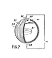
- FIGS. 7 and 8 show a second embodiment of the transducer of the invention.
- the membrane is a magnetostrictive sphere and the control means is an insulated electrical conductor wound around this membrane.
- the control means is an insulated electrical conductor wound around this membrane.
- FIG. 7 A first variant of this second embodiment is shown in FIG. 7.
- This transducer comprises a hollow sphere 50 of magnetostrictive material around which an insulated electrical conductor 52 is wound, thus forming a spherical coil 54.
- the hollow sphere 50 is produced in a single element by deposition, for example by evaporation under vacuum, of a layer of nickel alloy on a spherical mold, drilling a hole in the sphere then elimination of the mold by dissolution.
- the coil 54 is produced for example from copper wire having a diameter of the order of 0.1 mm to 0.2 mm for a sphere of a few centimeters in diameter.
- This copper wire is electrically insulated by enameling, sheathing or other.
- the turns of the coil are preferably contiguous, which improves the homogeneity and the sensitivity of the transducer.
- the rigidity of the coil is ensured by an appropriate coating layer (not shown).
- the ends 56 and 58 of the coil 54 which constitute the terminals of the electrical control means make it possible, in transmission, to apply an alternating voltage signal which is transformed by the sphere into an elastic wave. On reception, an alternating voltage signal corresponding to the received elastic wave is created at the ends 56, 58 of this coil, provided that, as in the previous case, a magnetic polarization of the sphere is provided.
- This embodiment has the advantage that the impedance between the terminals of the electrical control means is of the order of a few ohms (for a coil of a few centimeters in diameter in copper wire of 0.1 mm in diameter with turns contiguous) whereas in the transducers of FIGS. 2 and 4, this impedance is much lower. It is therefore possible in most cases to remove the impedance matching transformer.
- the sphere When using the transducer in a fluid such as water, the sphere must be equipped with means to equalize its internal and external pressures. This equalization can be achieved simply by at least one orifice 60 in the sphere in order to fill said sphere with the desired fluid. These orifices, which should not be covered by the coil 54, may advantageously be arranged near one end 56 or 58 of this coil. These equalization means are especially necessary if the transducer is used at a significant depth, in the case of water. They are useless if the working depth is small.
- the transducer shown in FIG. 7 can be supplemented by a polarization source.
- a polarization source Any polarization means known to a person skilled in the art can be used, for example a DC voltage source as shown in FIGS. 2 and 3 or a permanent magnet 61 placed in the sphere. The holding in position of this magnet can be easily obtained when the interior of the sphere is filled with a material absorbing elastic waves. The polarization is necessary in reception.
- the transducer can operate in emission without polarization. In this case however, the elastic wave emitted at a frequency double the applied alternating electrical signal.
- the operation of the omnidirectional transducer shown in Figure 7 is as follows. On reception, an elastic wave received generates a pulsation of the sphere made of magnetostrictive material. This pulsation induces an electric current in the coil 54 and therefore a modulation of the potential difference between the ends 56 and 58 of this coil. In transmission, the phenomenon is reversed: the variation in the potential difference between the ends 56 and 58 of the coil, and therefore of the current flowing through this coil, causes a modification of the magnetic field in this coil; this modification causes the pulsation of the sphere 50 and therefore the emission of an elastic wave.
- FIG. 8 A variant of the transducer of FIG. 7 is shown in FIG. 8.
- the turns of the electrical conductor 52 are no longer contiguous, which makes it possible not to increase the impedance between the ends 56 and 58 beyond a few ohms, even if the sphere 22 is of large dimension.
- the electrical conductor 52 is wound so as to create turns in a plane substantially perpendicular to the axis passing through the ends 56 and 58.
- the sphere can reach several tens of centimeters in diameter. It can then reproduce all sound frequencies (bass, mid and treble) and be used in high fidelity sound reproduction as a universal speaker.
- Figures 9 and 10 show a third embodiment of the omnidirectional elastic wave transducer of the invention.
- the transducer shown in Figure 9 consists of a spherical coil 72 obtained by winding a wire 74. For reasons of clarity of the figure, there is shown a coil with non-contiguous turns. It should be noted however that in practice, a winding with contiguous turns is preferable because the omnidirectionality is all the better as the coil is homogeneous.
- this wire 74 consists of a wire 76 of magnetostrictive material on which is wound an electrically conductive wire 78.
- the latter is electrically isolated from the magnetostrictive wire. It can consist for example of a sheathed or enameled copper wire.
- This electrically conductive wire constitute the ends 80, 82 of the spherical coil and the terminals of the electrical control means.
- the spherical coil 72 is continuously polarized for example by a DC voltage source 84.
- the polarization of the spherical coil is not compulsory when the transducer is used in emission but in this case the frequency of the applied AC signal. On the other hand, this polarization is necessary in reception.
- the tension applied to the ends 80 and 82 of the conductive wire is then modulated by the elastic wave received.
- This layer advantageously comprises at least one orifice 86 disposed for example near one of the ends 80 and 82 of the electrical conductor, to maintain equal pressures on the internal and external surfaces of the spherical coil, by allowing the fluid in which is immersed the transducer to enter said spherical coil.
- the internal and external pressure equalization orifices can be replaced by an elastic material filling the interior of the sphere.
- the magnetostrictive wire is directly wound on the sphere of elastic material.
- a hollow spherical mold is first produced from a rigid material, for example from plastic.
- a rigid material for example from plastic.
- the spherical mold can be produced by bonding two hemispheres.
- the wire 74 is then wound, consisting of a wire 76 of magnetostrictive material on which is wound an insulated electrically conductive wire 78; the ends of the insulated conducting wire 78 constitute the terminals making it possible to excite the magnetostrictive material or to detect a pulsation of the latter.
- the spherical coil is then made rigid by the deposition of a coating layer.
- At least one orifice 86 is drilled in this coating layer, for example near one of the ends of the conductive wire, so as to allow the elimination of the hollow mold.
- This elimination is obtained by immersing the spherical coil in a dissolving bath for this mold.
- the mold is made of a plastic material similar to that of ping pong balls, this dissolution is easily obtained by immersion of the spherical coil in acetone.
- the orifice provided for dissolving the mold also makes it possible to keep the internal and external pressures of the coil equal.
- the invention has been described with reference to a spherical magnetostrictive membrane transducer. This example was chosen because the sphere is the most omnidirectional emitter and because this shape is the most efficient in reproducing low frequencies for a given surface membrane. In fact, the lower frequency limit of the membrane is lower the larger the diameter of the membrane.
- the invention is not limited to a transducer comprising a spherical membrane.
- a transducer comprising a spherical membrane.
- the membranes of which respectively have the shape of a closed cylinder and of a portion of cylinder and are composed of a mesh of magnetostrictive material covered with or embedded in an electrically insulating layer, as in the case of FIG. 4.
- the membrane 88 of the transducer of FIG. 11 consists of a cylinder 90 with a circular base closed at its ends by two hemispheres 92, 94.
- the terminals of the control means are constituted by two connections 96.98 fixed to the top of the hemispheres 92 , 94.
- the impedance between the connections is a few ohms and it is not necessary to provide an impedance adapter in the case of use in high fidelity sound reproduction.
- a means of permanent polarization of the transducer must be provided.
- This means is arbitrary; by way of example, the transducer of FIG. 11 is provided with a DC voltage source 100.
- the transducer shown in FIG. 12 comprises a membrane 102 in the form of a portion of a cylinder. This surface is defined mathematically as a set of parallel lines of finite length resting on an arc of a circle.
- the terminals of the control means are constituted by electrical conductors 104, 106 in the form of an arc of a circle and connected to the lower and upper edges of the membrane.
- the transducer can be provided with a means of continuous polarization such as a DC voltage source 108.
- the inner face i.e. concave, can be covered with a material absorbing elastic waves.
- the transducer of the invention can also find an application in the transmission or reception of elastic waves which is very directive.
- An example of such an application is shown in FIG. 13 in the case where the membrane is spherical.
- the spherical membrane 112 is placed at the focal point of a paraboloid of revolution 112. This arrangement makes it possible to obtain, in emission, a unidirectional elastic wave of great intensity and in reception, a detector of great sensitivity.
Landscapes
- Physics & Mathematics (AREA)
- General Physics & Mathematics (AREA)
- Engineering & Computer Science (AREA)
- Acoustics & Sound (AREA)
- Signal Processing (AREA)
- Transducers For Ultrasonic Waves (AREA)
Description
La présente invention a pour objet un transducteur omnidirectionnel d'ondes élastiques à large bande passante. Par ondes élastiques, on entend une onde de pression se propageant dans un liquide ou dans un gaz. Dans ce dernier cas, une onde élastique est souvent appelée onde acoustique. La transducteur peut être utilisé en émission, et il convertit alors un signal électrique en une onde élastique, ou en réception, et il convertit alors une onde élastique en un signal électrique. Le transducteur de l'invention est adapté notamment à la transmission des ondes sonores et ultrasonores.The present invention relates to an omnidirectional transducer of elastic waves with a large passband. By elastic waves is meant a pressure wave propagating in a liquid or in a gas. In the latter case, an elastic wave is often called an acoustic wave. The transducer can be used in transmission, and it then converts an electrical signal to an elastic wave, or in reception, and it then converts an elastic wave in an electrical signal. The transducer of the invention is suitable in particular for the transmission of sound and ultrasonic waves.
La transmission sous-marine de signaux élastiques de fréquence élevée (ondes ultrasonores) constitue un domaine privilégié d'application de l'invention. Le transducteur peut y être utilisé comme hydrophone aussi bien en récepteur qu'en émetteur. La large bande passante de ce transducteur autorise la transmission de signaux de fréquence élevée tels que par exemple des signaux de télévision spécialement adaptés pour la transmission dans l'eau (bande passante d'environ 200 kHz), des signaux de parole ou tous autres signaux d'information.The submarine transmission of high frequency elastic signals (ultrasonic waves) constitutes a privileged field of application of the invention. The transducer can be used as a hydrophone in both receiver and transmitter. The wide bandwidth of this transducer allows the transmission of high frequency signals such as for example television signals specially adapted for transmission in water (bandwidth of about 200 kHz), speech signals or any other signals of information.
La reproduction sonore de haute-fidélité constitue un autre domaine privilégié d'application de l'invention. Le transducteur utilisé en émission réalise en haut-parleur de hautes performances à large bande passante.Another preferred field of application of the invention is high-fidelity sound reproduction. The transducer used in transmission achieves high-performance loudspeakers with wide bandwidth.
Le principe du transducteur de 4'invention est fondé sur l'effet de magnétostriction. La magnétostriction est la propriété pour certains corps de subir une modification géométrique (contraction, dilatation, flexion, torsion, ...) lorsqu'ils sont soumis à l'influence d'un champ magnétique. Les alliages métalliques et en particulier les composés ferromagnétiques sont des matériaux magnétostrictifs.The principle of the transducer of the invention is based on the effect of magnetostriction. Magnetostriction is the property for certain bodies to undergo a geometric modification (contraction, dilation, bending, torsion, ...) when they are subjected to the influence of a magnetic field. Metal alloys and in particular ferromagnetic compounds are magnetostrictive materials.
L'utilisation de tels matériaux pour la conversion d'une onde électrique en une onde élastique n'est pas nouvelle. Elle est décrite notamment dans le brevet US-A-2 670 446 et dans la revue "Engineering" janvier 1969-pages 117-120, ainsi que dans le brevet FR-A-2 340 014 intitulé "transducteur électroacoustique à noyau magnétostrictif".The use of such materials for the conversion of an electric wave into an elastic wave is not new. It is described in particular in US-A-2,670,446 and in the journal "Engineering" January 1969-pages 117-120, as well as in patent FR-A-2,340,014 entitled "electroacoustic transducer with magnetostrictive core".
Dans ce brevet, le transducteur comporte principalement un barreau magnétostrictif disposé dans un solénoïde. Lorsqu'un signal de tension électrique est appliqué aux bornes de la bobine, il se crée dans l'axe du solénoïde un champ magnétique qui dilate ou contracte le barreau magnétostrictif selon la nature du matériau magnétostrictif employé. Ceci crée, au niveau de chacune des extrémités du barreau magnétostrictif, une onde élastique qui se propage suivant une direction sensiblement parallèle à l'axe du barreau magnétostrictif.In this patent, the transducer mainly comprises a magnetostrictive bar arranged in a solenoid. When an electrical voltage signal is applied across the coil, a magnetic field is created in the axis of the solenoid which expands or contracts the magnetostrictive rod depending on the nature of the magnetostrictive material used. This creates, at each of the ends of the magnetostrictive bar, an elastic wave which propagates in a direction substantially parallel to the axis of the magnetostrictive bar.
Il s'agit donc ici d'un transducteur électroacoustique monodirectionnel puisque l'onde élastique n'est émise que suivant la direction de l'axe du barreau. Ce caractère d'émission axial n'est pas souhaité dans toutes les applications et peut même constituer un inconvénient important, notamment dans le cas de la reproduction d'ondes sonores en haute fidélité où l'on désire au contraire que l'onde élastique soit émise avec la même intensité dans toutes les directions.It is therefore here a monodirectional electroacoustic transducer since the elastic wave is emitted only along the direction of the axis of the bar. This axial emission character is not desired in all applications and can even constitute a significant drawback, in particular in the case of the reproduction of sound waves in high fidelity where it is desired, on the contrary, for the elastic wave to be emitted with the same intensity in all directions.
Le brevet EP-A-0 063 094 ou aussi FR-A-2 503 516 intitulé "haut-parleur omnidirectionnel pour les fréquences aigues du spectre sonore" décrit un transducteur électroacoustique utilisable dans l'air qui autorise la production d'une onde élastique sensiblement omnidirectionnelle à partir de la dilatation linéaire ou de la contraction linéaire selon le matériau employé, d'un barreau magnétostrictif. On a représenté sur la figure 1 un mode de réalisation d'un haut-parleur selon l'enseignement de ce brevet.Patent EP-A-0 063 094 or also FR-A-2 503 516 entitled "omnidirectional loudspeaker for the acute frequencies of the sound spectrum" describes an electroacoustic transducer usable in air which authorizes the production of an elastic wave substantially omnidirectional from linear expansion or linear contraction depending on the material used, of a magnetostrictive bar. FIG. 1 shows an embodiment of a loudspeaker according to the teaching of this patent.
Ce haut-parleur comprend essentiellement deux hémisphères rigides 2 et 4 reliés l'un à l'autre par un joint annulaire élastique 6, auquel ils peuvent être fixés par collage, de manière à former une sphère pulsante, et un élément de commande 8 disposé à l'intérieur de la sphère et relié rigidement aux hémisphères 2 et 4.This loudspeaker essentially comprises two rigid hemispheres 2 and 4 connected to each other by an elastic annular seal 6, to which they can be fixed by gluing, so as to form a pulsating sphere, and a control element 8 disposed inside the sphere and rigidly connected to hemispheres 2 and 4.
L'élément de commande 8 a une forme allongée et peut subir une variation de longueur en réponse à un signal électrique devant être converti en onde élastique. Cet élément de commande est orienté à l'intérieur de la sphère de telle manière que les forces résultant de ces variations de longueur soient transmises aux hémisphères 2 et 4 dans des directions perpendiculaires au plan de raccordement desdits hémisphères.The control element 8 has an elongated shape and can undergo a variation in length in response to an electrical signal to be converted into an elastic wave. This control element is oriented inside the sphere in such a way that the forces resulting from these length variations are transmitted to the hemispheres 2 and 4 in directions perpendicular to the connection plane of said hemispheres.
La longueur de cet élément de commande 8 est de préférence inférieur au diamètre de la sphère et il est alors relié aux hémisphères 2 et 4 par des pièces rigides de transmission 10 et 12 qui prennent perpendiculairement appui sur les hémisphères 2 et 4 à des endroits suffisamment éloignés de la région de leurs sommets pour que chacun desdits hémisphères se déplace ou vibre d'un seul tenant, en réponse aux variations de longueur de l'élément de commande 8. Ces pièces de transmission ont sensiblement la forme d'une calotte sphérique.The length of this control element 8 is preferably less than the diameter of the sphere and it is then connected to the hemispheres 2 and 4 by
L'élément de commande 8 est constitué d'un barreau 14, à section circulaire ou carrée, en un matériau magnétostrictif, autour duquel est disposée une bobine d'induction 16. Le signal électrique devant être converti en onde élastique est appliqué aux extrémités de la bobine 16 par deux conducteurs électriques 18 et 20 qui passent à travers une ouverture formée dans le joint annulaire 6.The control element 8 consists of a
Les pièces de transmission 10 et 12 permettent de convertir la dilatation linéaire du barreau magnétostrictif 14 en un déplacement de chacun des deux hémisphères 2 et 4. L'onde élastique produire est donc sensiblement omnidirectionnelle.The
Cependant, l'onde produite ne peut être parfaitement omnidirectionnelle. Ceci est dû en partie à la présence du joint annulaire élastique 6 qui relie les deux hémisphères et qui interdit donc l'émission de l'onde sonore dans on plan, et ceci est dû également au fait que les pièces de transmission ne modifient pas le caractère linéaire de la force transmise. ln ne s'agit donc pas exactement d'une sphère pulsante, c'est-à-dire ayant un rayon variable mais identique en chaque point à un instant donné, mais simplement de deux hémisphères ayant simultanément un mouvement linéaire de même direction et de sens opposé. C'est aussi le cas du haut-parleur décrit dans le brevet EP-A-0 063 094.However, the wave produced cannot be perfectly omnidirectional. This is partly due to the presence of the elastic annular seal 6 which connects the two hemispheres and which therefore prohibits emitting sion of the sound wave in the plane, and this is also due to the fact that the transmission parts do not modify the linear character of the force transmitted. It is therefore not exactly a pulsating sphere, that is to say having a variable radius but identical at each point at a given instant, but simply two hemispheres having simultaneously a linear movement of the same direction and of opposite. This is also the case of the loudspeaker described in patent EP-A-0 063 094.
Le but de l'invention est de remédier aux inconvénients des dispositifs connus, notamment à leur absence de réelle omnidirectionnalité.The object of the invention is to remedy the drawbacks of known devices, in particular their absence of real omnidirectionality.
Ce but est atteint par un transducteur conforme à la revendication 1 ou fabriqué selon le procédé de la revendication 12.This object is achieved by a transducer according to
La membrane du transducteur de l'invention peut également être en forme de surface non fermée; dans le cas d'une forme hémisphérique par exemple, le transducteur est omnidirectionnel dans un demi-plan de l'espace.The membrane of the transducer of the invention can also be in the form of an unclosed surface; in the case of a hemispherical shape for example, the transducer is omnidirectional in a half-plane of space.
De manière avantageuse, la membrane est équipée de moyens pour égaliser ses pressions interne et externe. Ceci est particulièrement important dans le cas par exemple où l'on désire utiliser le transducteur sous l'eau à des profondeurs variables.Advantageously, the membrane is equipped with means for equalizing its internal and external pressures. This is particularly important in the case for example where it is desired to use the transducer underwater at variable depths.
L'égalisation des pressions interne et externe peut être réalisée simplement en perçant au moins un orifice de petite dimension dans la membrane. La pression sur la face externe de la membrane peut également être compensée en remplissant le volume intérieur de la membrane par un matériau élastique. Dans le cas où le membrane est plongée dans un liquide, par exemple de l'eau, la compensation n'est parfaite que pour une profondeur donnée. Ce mode de réalisation permet toutefois d'utiliser le transducteur sur une certaine plage de profondeur.Internal and external pressure equalization can be achieved simply by drilling at least one small orifice in the membrane. The pressure on the external face of the membrane can also be compensated for by filling the internal volume of the membrane with an elastic material. In the case where the membrane is immersed in a liquid, for example water, the compensation is only perfect for a given depth. This embodiment however allows the transducer to be used over a certain depth range.
De manière préférée, le volume intérieur de la membrane est rempli d'un matériau absorbant les ondes élastiques, tel que du coton ou de la laine de verre, pour absorber les ondes élastiques émises par chaque élément de surface de la membrane dans ledit volume intérieur afin d'éviter des reflexions parasites.Preferably, the interior volume of the membrane is filled with a material absorbing elastic waves, such as cotton or glass wool, to absorb the elastic waves emitted by each surface element of the membrane in said interior volume. in order to avoid parasitic reflections.
Les caractéristiques et avantages de l'invention ressortiront mieux de la description qui va suivre, donnée à titre illustratif mais non limitatif, en référence aux dessins annexés, sur lesquels:
- -la figure 1, déjà décrite, illustre un transducteur électroacoustique sensiblement omnidirectionnel selon l'art antérieur,
- -la figure 2 illustre un premier mode de réalisation du transducteur omnidirectionnel d'ondes élastiques de l'invention, dans lequel la membrane est constituée par une couche magnétostrictive,
- -la figure 3 illustre une variante de réalisation du transducteur de la figure 2 dans lequel la membrane est obtenue à partir d'une bande magnétostrictive,
- -la figure 4 illustre une autre variante de réalisation du transducteur omnidirectionnel d'ondes élastiques de la figure 2,
- -les figures 5a et 5b sont des chronogrammes représentant respectivement un signal électrique Ve appliqué à la membrane des transducteurs des figures 2 et 3 et l'onde élastique A correspondante émise,
- -les figures 6a et 6b sont des chronogrammes représentant respectivement un signal électrique V. appliqué à la membrane du transducteur de la figure 4 et l'onde élastique A correspondante émise,
- -la figure 7 illustre un deuxième mode de réalisation du transducteur de l'invention dans lequel le moyen de commande électrique est un conducteur électrique isolé bobiné sur la membrane,
- -la figure 8 illustre une variante de réalisation du transducteur de la figure 7,
- -la figure 9 illustre un troisième mode de réalisation du transducteur de l'invention dans lequel la membrane est obtenue par bobinage d'un fil magnétostrictif,
- -la figure 10 montre l'enroulement d'un conducteur électrique constituant le moyen de commande électrique autour du fil magnétostrictif du transducteur de la figure 9,
- -la figure 11 illustre un mode de réalisation du transducteur de l'invention à membrane cylindrique,
- -la figure 12 illustre un mode de réalisation du transducteur de l'invention dont la membrane est une portion de cylindre, et
- -la figure 13 illustre l'application d'un transducteur omnidirectionnel d'onde élastiques à membrane sphérique conforme à l'invention à la production d'une onde élastique intense parfaitement unidirectionnelle.
- FIG. 1, already described, illustrates a substantially omnidirectional electroacoustic transducer according to the prior art,
- FIG. 2 illustrates a first embodiment of the omnidirectional elastic wave transducer of the invention, in which the membrane consists of a magnetostrictive layer,
- FIG. 3 illustrates an alternative embodiment of the transducer of FIG. 2 in which the membrane is obtained from a magnetostrictive strip,
- FIG. 4 illustrates another alternative embodiment of the omnidirectional elastic wave transducer of FIG. 2,
- FIGS. 5a and 5b are timing diagrams respectively representing an electrical signal V e applied to the membrane of the transducers of FIGS. 2 and 3 and the corresponding elastic wave A emitted,
- FIGS. 6a and 6b are timing diagrams respectively representing an electrical signal V. applied to the membrane of the transducer of FIG. 4 and the corresponding elastic wave A emitted,
- FIG. 7 illustrates a second embodiment of the transducer of the invention in which the electrical control means is an insulated electrical conductor wound on the membrane,
- FIG. 8 illustrates an alternative embodiment of the transducer of FIG. 7,
- FIG. 9 illustrates a third embodiment of the transducer of the invention in which the membrane is obtained by winding a magnetostrictive wire,
- FIG. 10 shows the winding of an electrical conductor constituting the electrical control means around the magnetostrictive wire of the transducer of FIG. 9,
- FIG. 11 illustrates an embodiment of the transducer of the invention with a cylindrical membrane,
- FIG. 12 illustrates an embodiment of the transducer of the invention, the membrane of which is a portion of a cylinder, and
- FIG. 13 illustrates the application of an omnidirectional elastic wave transducer with a spherical membrane according to the invention to the production of an intense elastic wave which is perfectly unidirectional.
Dans la description qui suit, on décrit plusieurs modes de réalisation d'un transducteur selon l'invention dans lequel la membrane est une sphère. Il est bien entendu que cette forme est prise à titre d'exemple et que le transducteur de l'invention peut être pourvu d'une membrane ayant une forme quelconque qui peut être fermée (ellipsoïde, cylindre fermé, ...) ou ouverte (hémisphérique, cône, cylindre, ouvert, ...). Cette membrane n'est pas nécessairement une surface de révolution.In the description which follows, several embodiments of a transducer according to the invention are described in which the membrane is a sphere. It is understood that this shape is taken by way of example and that the transducer of the invention can be provided with a membrane having any shape which can be closed (ellipsoid, closed cylinder, ...) or open ( hemispherical, cone, cylinder, open, ...). This membrane is not necessarily a surface of revolution.
On a représenté sur la figure 2 un premier mode de réalisation du transducteur omnidirectionnel d'ondes élastiques de l'invention. Il est constitué d'une sphère creuse 22 en matériau magnétostrictif constituant la membrane et est muni en deux points diamétralement opposés de connexions électriques 24 et 26 constituant les bornes du moyen de commande électrique.FIG. 2 shows a first embodiment of the omnidirectional elastic wave transducer of the invention. It consists of a
Les matériau magnétostrictifs sont bien connus de l'homme de l'art. Rappelons simplement qu'ils sont classés en quatre groupes principaux qui sont les alliages métalliques, les ferrites, les composés fer-terres rares et les composés amorphés magnétiques ou verres métalliques. Parmi les alliages métalliques les plus utilisés, on peut citer le nickel polycristallin, certains alliages fer-nickel, fer-aluminium, nickel-cobalt et fer- cobalt.Magnetostrictive materials are well known to those skilled in the art. Let us simply recall that they are classified into four main groups which are metal alloys, ferrites, iron-rare earth compounds and magnetic amorphous compounds or metallic glasses. Among the most commonly used metal alloys, polycrystalline nickel, certain alloys may be mentioned. iron-nickel, iron-aluminum, nickel-cobalt and iron-cobalt.
Les alliages de nickel-cobalt sont des matériaux intéressants en ce qu'ils cumulent les avantages de posséder un fort coefficient de couplage électromécanique, d'être faciles à fabriquer et d'être très résistants à la corrosion. A titre d'exemple, un matériau comprenant 96% de nickel et 4% de cobalt a un coefficient de couplage électromécanique de 0,5.Nickel-cobalt alloys are attractive materials in that they combine the advantages of having a high electromechanical coupling coefficient, of being easy to manufacture and of being very resistant to corrosion. For example, a material comprising 96% nickel and 4% cobalt has an electromechanical coupling coefficient of 0.5.
La sphère 22 est une sphère pulsante homogène. Ainsi, lorsqu'une différence de tension est appliquée entre les connexions 24 et 26 de la sphère, tous les points de la sphère constituent des émetteurs identiques d'ondes élastiques et la sphère est par conséquent un émetteur d'onde élastique omnidirectionnel parfait.The
Le courant traversant la sphère suit les méridiens 28. Ce courant est plus important par unité de surface près des pôles (connexions 24, 36) que près de l'équateur, ce qui favorise une plus grande amplitude de pulsation près des pôles. Cependant, les connexions 24,26 rendent plus rigide la sphère près des pôles, ce qui limite l'amplitude de pulsation. Ces deux effets antagonistes s'équilibrent sensiblement, tous les éléments de surface de la sphère ont donc à peu près la même amplitude de vibration.The current passing through the sphere follows the
L'impédance entre les connexions 24, 26 est faible. Pour une sphère de quelques centimètre de diamètre et de quelques microns d'épaisseur, elle est de l'ordre de quelques dixièmes d'ohm. Cette impédance est faible et nécessite un transformateur d'adaptation 30 pour pouvoir être branché directement sur les amplificateurs usuels, utilisés par exemple dans le domaine de la haute fidélité.The impedance between the
Ce transformateur d'adaptation d'impédance peut être supprimé dans le cas où l'impédance de la sphère 22 entre les connexions 24, 26 est de quelques ohms. Le transducteur de la figure 3 en est une illustration.This impedance matching transformer can be eliminated in the case where the impedance of the
Dans cette figure, les éléments identiques à ceux de la figure 2 portent les mêmes références. La sphère 22 s'obtient à partir de celle de la figure 2 par un découpage en bande analogue à celle obtenue en pelant un fruit. Un joint élastique 33 permet de reconstituer une sphère rigide.In this figure, the elements identical to those of Figure 2 have the same references. The
L'impédance de la sphère, qui est fonction de la longueur d'un méridien 28 dans letransducteurde la figure 2, est fonction de la longueur et de la largeur de la bande magnétostrictive dans le transducteur de la figure 3. Elle est donc plus important dans ce dernier cas et peut être ajustée, pour une sphère fixée, en fonction de la largeur de la bande.The impedance of the sphere, which is a function of the length of a
L'émetteur de l'invention présente l'avantage sur les appareils connus d'avoir une très large bande passante. A titre d'exemple, cette bande passante s'étend de quelques kilohertz à plusieurs centaines de kilohertz pour une sphère de 4 cm de diamètre. La fréquence centrale de la bande passente est liée à la taille de la sphère. Pour l'émission de fréquences basses, il faut déplacer un volume important de fluide (eau, air, ...); la sphère a dans ce cas un diamètre adéquat.The transmitter of the invention has the advantage over known devices of having a very wide bandwidth. For example, this bandwidth extends from a few kilohertz to several hundred kilohertz for a sphere 4 cm in diameter. The center frequency of the passband is related to the size of the sphere. For the emission of low frequencies, it is necessary to move a large volume of fluid (water, air, ...); the sphere in this case has an adequate diameter.
Des expériments ont montré que la puissance de l'onde élastique émise peut être appréciable. Cette puissance acoustique est principalement limitée par deuxfacteurs qui sont, d'une part, la saturation magnétique du matériel magnétostrictif par un champ magnétique trop intense et, d'autre part, l'échauffement excessif de la sphère. Il est intéressant de noter que la puissance relative maximale que l'on peut appliquer à la sphère est nettement plus importante si elle est plongée dans l'eau que si elle est plongée dans l'air. Une sphère en alliage Nickel-Cobalt de 4 cm de diamètre et de 0,01 mm d'épaisseur peut ainsi absorber sans problème une charge supérieur à 50 W.Experiments have shown that the power of the elastic wave emitted can be appreciable. This acoustic power is mainly limited by two factors which are, on the one hand, the magnetic saturation of the magnetostrictive material by an excessively strong magnetic field and, on the other hand, the excessive heating of the sphere. It is interesting to note that the maximum relative power that can be applied to the sphere is much greater if it is immersed in water than if it is immersed in air. A sphere made of Nickel-Cobalt alloy 4 cm in diameter and 0.01 mm thick can thus easily absorb a load greater than 50 W.
Selon un mode de réalisation préféré, la sphère 22 (figures 2 et 3) est polarisée en continu par une source de tension continue 32. Ceci permet de créer une onde acoustique dont l'amplitude A représentée sur la figure 5b est proportionnelle au signal de tension électrique Ve appliqué aux bornes de la sphère 22 et représenté sur la figure 5a.According to a preferred embodiment, the sphere 22 (FIGS. 2 and 3) is continuously polarized by a
Lorsque le transducteur comprend un transformateur d'adaptation d'impédance 30 et une source de tension continue 32, comme c'est le cas du transducteur de la figure 2, ces deux éléments sont de préférence découplés. Ils sont disposés en parallèle aux bornes 24 et 26 de la sphère 22. Le montage est complété classiquement par un condensateur 29 en série avec le transformateur 30 pour empêcher la propagation d'un signal électrique continu dans le transformateur, et par une inductance 31 en série avec la source 32 pour empêcher la propagation d'un signal transitoire dans la source 32.When the transducer comprises an
La polarisation de la sphère n'est pas obligatoire lorsque le transducteur est utilisé en émission mais ceci a pour conséquence de doubler les fréquences du signal électrique. En revanche, cette polarisation est nécessaire en réception. La tension appliquée aux pôles de la sphère est alors modulée par l'onde élastique reçue.The polarization of the sphere is not compulsory when the transducer is used in emission but this has the consequence of doubling the frequencies of the electrical signal. On the other hand, this polarization is necessary in reception. The tension applied to the poles of the sphere is then modulated by the elastic wave received.
Les sphères représentées sur les figures 2 et 3 sont munies de deux orifices 34 qui permettent de maintenir égales les pressions sur ses surfaces interne et externe. Le nombre de ces orifices est quelconque, mais en général, un ou deux orifices sont suffisants. La taille de ces orifices est de préférence petite pour ne pas perturber l'homogénéité de la sphère.The spheres represented in FIGS. 2 and 3 are provided with two
Ces moyens d'égalisation ne sont pas nécessaires si la sphère est plongée dans l'air. En revanche, si elle est utilisée par exemple dans l'eau, la pression exercée sur la face externe de la sphère est important et doit être compensée. Les orifices 34 réalisant cette compensation.These equalization means are not necessary if the sphere is immersed in the air. On the other hand, if it is used for example in water, the pressure exerted on the external face of the sphere is important and must be compensated. The
Il est bien connu que l'eau pure est inélastique. Elle ne peut donc pas être utilisée pour remplir la sphère qui ne pourrait alors plus pulser. En revanche, il n'y a pas d'inconvénient à utiliser de l'eau naturelle (eau de mer, de lac, ...) qui, contenant de l'oxygène libre et des microorga- nismes, possède une certaine élasticité.It is well known that pure water is inelastic. It cannot therefore be used to fill the sphere which could then no longer pulsate. On the other hand, there is no disadvantage in using natural water (sea water, lake water, etc.) which, containing free oxygen and microorganisms, has a certain elasticity.
Les orifices peuvent être remplacés par un matériau élastique remplissant l'intérieur de la sphère. Dans ce dernier cas, la sphère est fabriquée de la manière suivante. On réalise une sphère dans un matériau élastique par exemple une mousse puis on dépose, selon tout procédé connu et par exemple par évaporation sous vide, une couche homogène de matériau magnétostrictif sur toute la surface de cette sphère.The orifices can be replaced by an elastic material filling the interior of the sphere. In the latter case, the sphere is manufactured in the following manner. A sphere is produced in an elastic material, for example a foam, and then, according to any known method and for example by evaporation under vacuum, a homogeneous layer of magnetostrictive material is deposited over the entire surface of this sphere.
On va maintenant décrire un mode particulier de fabrication de la sphère creuse en un seul élément représentée sur la figure 2. On réalise d'abord un moule sphérique creux en une matière rigide, par exemple en matière plastique. On peut par exemple utiliser une matière plastique semblable à celle qui est utilisée pour la fabrication des balles de ping-pong. Comme ces dernières, le moule sphérique pourra être réalisé par collage de deux hémisphères.We will now describe a particular method of manufacturing the hollow sphere in a single element shown in Figure 2. First, a hollow spherical mold is made of a rigid material, for example plastic. One can for example use a plastic material similar to that which is used for the manufacture of ping-pong balls. Like the latter, the spherical mold can be produced by bonding two hemispheres.
On recouvre ensuite le moule sphérique d'une couche d'un matériau électriquement conducteur, par exemple un métal tel que cuivre. Cette couche se fait selon des techniques connues telles que le dépôt chimique en phase vapeur. L'épaisseur de cette couche est par exemple de 0,01 mm. On dépose ensuite une couche de matiériau magné- . tostrictif par électrolyse. Ce matériau magnétostrictif est par exemple un alliage nickel-cobalt et son épaisseur peut être de l'ordre de 0,01 mm pour une sphère ayant un diamètre de 4 cm.The spherical mold is then covered with a layer of an electrically conductive material, for example a metal such as copper. This layer is made according to known techniques such as chemical vapor deposition. The thickness of this layer is for example 0.01 mm. A layer of magnesium material is then deposited. tostrictive by electrolysis. This magnetostrictive material is for example a nickel-cobalt alloy and its thickness can be of the order of 0.01 mm for a sphere having a diameter of 4 cm.
Dans une étape suivante, on perce deux trous en deux points diamétralement opposés de la sphère. Ces trous permettent d'éliminer le moule creux et la couche électriquement conductrice. Ils seront utilisés ultérieurement pour recevoir les connexions 24 et 26.In a next step, two holes are drilled at two diametrically opposite points on the sphere. These holes eliminate the hollow mold and the electrically conductive layer. They will be used later to receive
On plonge alors la sphère dans un bain pour dissoudre le moule. Dans le cas où ce moule est en une matière plastique semblable à celle des balles de ping-pong, la dissolution s'obtient aisément par immersion de la sphère dans l'acétone. Enfin, on élimine la couche électriquement conductrice par une attaque chimique n'attaquant pas le nickel.We then immerse the sphere in a bath to dissolve the mold. In the case where this mold is made of a plastic material similar to that of ping-pong balls, the dissolution is easily obtained by immersion of the sphere in acetone. Finally, the electrically conductive layer is eliminated by a chemical attack which does not attack the nickel.
La sphère creuse en matériau magnétostrictif est lors réalisée. Il ne reste plus qu'à souder les fils électriques au niveau des deux trous de la sphère de manière à réaliser les connexions 24 et 26. On peut enfin percer un ou plusieurs orifices 34 pour égaliser les pressions interne et externe si la sphère est utilisée dans l'eau (hydrophone) ou dans un liquide en général.The hollow sphere made of magnetostrictive material is then produced. It only remains to solder the electric wires at the level of the two holes of the sphere so as to make the
Une variante du procédé de fabrication de la sphère consiste à déposer directement, par exemple par dépôt électrolytique, la couche de matériau magnétostrictif sur le moule. Ceci permet de supprimer l'étape de dépôt d'une couche de matériau électriquement conducteur. Le demandeur a réalisé des sphères suivant chacun des ces procédés. Elles sont réalisées en un alliage comprenant environ 90% de nickel et 10% de cobalt.A variant of the process for manufacturing the sphere consists in depositing directly, for example by electrolytic deposition, the layer of magnetostrictive material on the mold. This eliminates the step of depositing a layer of electrically conductive material. The applicant has produced spheres according to each of these methods. They are made of an alloy comprising approximately 90% nickel and 10% cobalt.
De manière générale, toute méthode connue de dépôt sur un moule peut être utilisée.In general, any known method of deposition on a mold can be used.
On a décrit deux procédés de fabrication d'une sphère en un seul élément. Ces procédés de fabrication peuvent être délicats à mettre en oeuvre dans certains cas particuliers, notamment lorsque l'on désire réaliser une sphère ayant un diamètre important (supérieur à une dizaine de centimètres, par exemple). Dans ce cas, il peut être préférable de fabriquer séparément deux hémisphères identiques en matériau magnétostrictif et de souder ensuite ensemble ces deux hémisphères.Two methods of making a sphere from a single element have been described. These manufacturing methods can be difficult to implement in certain particular cases, in particular when it is desired to produce a sphere having a large diameter (greater than ten centimeters, for example). In this case, it may be preferable to separately manufacture two identical hemispheres of magnetostrictive material and then weld these two hemispheres together.
Une sphère obtenue suivant ce procédé de fabrication est représentée schématiquement sur la figure 4. Cette sphère est constituée de deux hémisphères creux 36 et 38 composés chacun d'un grillage magnétostrictif 37, ou de matériaux analogues tels qu'une toile, une tôle fine percée de trous ou autre, recouvert du ou noyé dans une couche électriquement isolante 39. Cette couche permet de boucher les trous du grillage, ce qui est nécessaire pour obtenir un bon rendement de conversion électro-acoustique. Ce grillage a une maille de l'ordre de 1 mm de côté. Les deux séries de fils croisés peuvent être toutes les deux en matériau magnétostrictif. Mais ou peut également utiliser un grillage dont seule la série de fils formant les méridiens de la sphère (les connexions 24 et 26 formant les pôles) sont en matériau magnétostrictif, l'autre série de fils pouvant être en matière quelconque, notamment électriquement isolante. Lorsque ce mode de réalisation est utilisé pour la génération des sous dans l'air, cette couche isolante peut être obtenue par l'application d'une matière telle que celle utilisée pour la fabrication des haut-parleurs classiques.A sphere obtained according to this manufacturing process is shown diagrammatically in FIG. 4. This sphere consists of two
Pour faciliter leur raccordement par soudage, la base de chaque hémisphère peut comprendre une collerette 40 et 42. Les deux hémisphères sont réunis par exemple par soudage à l'étain ou soudage sous argon, le cordon de soudure venant s'appuyer sur chaque collerette.To facilitate their connection by welding, the base of each hemisphere can comprise a
De préférence, les connexions 24 et 28 sont réalisées en deux points diamétralement opposés de la sphère situés sur le cordon de soudure. Ceci permet d'avoir une sphère pulsante pratiquement homogène puisque tous les méridiens reliant les deux connexions 24 et 26 qui forment les pôles sont identiques à l'exception des deux seuls méridiens correspondant au cordon de soudure 44.Preferably, the
La sphère 22 représentée sur la figure 4 fonctionne exactement de la même manière que la sphère 22 représentée sur la figure 2. Elle peut être utilisée aussi bien en émission qu'en réception. En émission, elle peut être polarisée ou non; en réception, elle droit être polarisée.The
Dans le cas où la sphère est utilisée en émission et n'est pas polarisée, comme on l'a représenté à titre d'exemple sur la figure 4, le signal électrique alternatif qui doit être converti en une onde élastique est transmis directement aux deux connexions 24 et 36 et la sphère par l'intermédiaire d'un adaptateur d'impédance qui peut être un simple transformateur 30.In the case where the sphere is used in emission and is not polarized, as shown by way of example in FIG. 4, the alternating electrical signal which must be converted into an elastic wave is transmitted directly to the two
Les figures 6a et 6b illustrent la relation entre le signal électrique V. appliqué aux connexions 24 et 26 de la sphère 22 de la figure 4 et la caractéristique A de l'onde élastique émise en l'absence de polarisation de la sphère. La sphère constitue ici un émetteur qui double la fréquence du signal électrique.FIGS. 6a and 6b illustrate the relationship between the electrical signal V. applied to the
La sphère représentée sur la figure 4 peut également être réalisée à partir de deux hémisphères ayant chacun une structure identique à celle de la sphère représentée sur la figure 1. Les hémisphères sont fabriqués de la même manière que la sphère de la figure 1 puis sont réunis par soudage, collage ou autre.The sphere shown in Figure 4 can also be made from two hemispheres each having a structure identical to that of the sphere shown in Figure 1. The hemispheres are made in the same way as the sphere of Figure 1 and then are joined by welding, gluing or other.
Une autre méthode, efficace, facile et bon marché, de fabrication d'hémisphères en matière magnétostrictive, est l'emboutissage. Cette technique permet d'obtenir sans difficultées des hémisphères de plusieurs dizaines de centimètre de diamètre. Ceci est particulièrement avantageux car un transducteur unique peut alors reproduire toutes les fréquences du spectre sonore.Another efficient, easy and inexpensive method of manufacturing magnetostrictive hemispheres is stamping. This technique allows hemispheres of several tens of centimeters in diameter to be obtained without difficulty. This is particularly advantageous since a single transducer can then reproduce all the frequencies of the sound spectrum.
On a représenté sur les figures 7 et 8 un deuxième mode de réalisation du transducteur de l'invention. Dans ces figures, la membrane est une sphère magnétostrictive et le moyen de commande est un conducteur électrique isolé bobiné autour de cette membrane. A la différence du premier mode de réalisation illustré par les figures 2 à 4, il n'y a plus dans le transducteur selon les figures 7 et 8 de contact électrique entre la membrane et le moyen de commande électrique.FIGS. 7 and 8 show a second embodiment of the transducer of the invention. In these figures, the membrane is a magnetostrictive sphere and the control means is an insulated electrical conductor wound around this membrane. Unlike the first embodiment illustrated in Figures 2 to 4, there is no longer in the transducer according to Figures 7 and 8 of electrical contact between the membrane and the electrical control means.
Une première variante de ce deuxième mode de réalisation est représentée sur la figure 7. Ce transducteur comprend une sphère creuse 50 en matériau magnétostrictif autour de laquelle est bobiné un conducteur électrique isolé 52, formant ainsi une bobine sphérique 54.A first variant of this second embodiment is shown in FIG. 7. This transducer comprises a
La sphère creuse 50 est réalisée en un seul élément par dépôt, par exemple par évaporation sous vide, d'une couche d'alliage au nickel sur un moule sphérique, perçage d'un trou dans la sphère puis élimination du moule par dissolution.The
La bobine 54 est réalisée par exemple en fil de cuivre ayant un diamètre de l'ordre de 0,1 mm à 0,2 mm pour une sphère de quelques centimètres de diamètre. Ce fil de cuivre est isolé électriquement par émaillage, gainage ou autre. Les spires de la bobine sont de préférence jointives, ce qui améliore l'homogénéité et la sensibilité du transducteur. La rigidité de la bobine est assurée par une couche d'enrobage appropriée (non représentée).The
Les extrémités 56 et 58 de la bobine 54 qui constituent les bornes du moyen de commande électrique permettent, en émission, d'appliquer un signal de tension alternatif qui est transformé par la sphère en une onde élastique. A la réception, il se crée aux extrémités 56, 58 de cette bobine un signal de tension alternatif correspondant à l'onde élastique reçue, pourvu que comme dans le cas précédentes une polarisation magnétique de la sphère soit prévue.The ends 56 and 58 of the
Ce mode de réalisation présente l'avantage que l'impédance entre les bornes du moyen de commande électrique est de l'ordre de quelques ohms (pour une bobine de quelques centimètres de diamètre en fil de cuivre de 0,1 mm de diamètre à spires jointives) alors que dans les transducteurs des figures 2 et 4, cette impédance est beaucoup plus faible. Il est donc possible de supprimer dans la plupart des cas le transformateur d'adaptation d'impédance.This embodiment has the advantage that the impedance between the terminals of the electrical control means is of the order of a few ohms (for a coil of a few centimeters in diameter in copper wire of 0.1 mm in diameter with turns contiguous) whereas in the transducers of FIGS. 2 and 4, this impedance is much lower. It is therefore possible in most cases to remove the impedance matching transformer.
Dans le cas d'une utilisation du transducteur dans un fluide tel que l'eau, la sphère doit être équipée de moyens pour égaliser ses pressions interne et externe. Cette égalisation peut être réalisée simplement par au moins un orifice 60 dans la sphère afin de remplir ladite sphère avec le fluide désiré. Ces orifices, ne devant pas être recouverts par la bobine 54, pourront être disposés avantageusement près d'une extrémité 56 ou 58 de cette bobine. Ces moyens d'égalisation sont surtout nécessaires si le transducteur est utilisé à une profondeur importante, dans le cas de l'eau. Ils sont inutiles si la profondeur de travail est faible.When using the transducer in a fluid such as water, the sphere must be equipped with means to equalize its internal and external pressures. This equalization can be achieved simply by at least one
Le transducteur représenté sur la figure 7 peut être complété par une source de polarisation. Tout moyen de polarisation connu de l'homme de l'art peut être employé, par exemple une source de tension continue comme on l'a représenté sur les figures 2 et 3 ou un aimant permanent 61 disposé dans la sphère. Le maintien en position de cet aimant peut être facilement obtenu lorsque l'intérieur de la sphère est remplie d'un matériau absorbant les ondes élastiques. La polarisation est nécessaire en réception. En revanche, le transducteur peut fonctionner en émission sans polarisation. Dans ce cas cependent, l'onde élastique émise a une fréquence double du signal électrique alternatif appliqué.The transducer shown in FIG. 7 can be supplemented by a polarization source. Any polarization means known to a person skilled in the art can be used, for example a DC voltage source as shown in FIGS. 2 and 3 or a
Le fonctionnement du transducteur omnidirectionnel représenté sur la figure 7 est le suivant. En réception, une onde élastique reçue engendre une pulsation de la sphère en matériau magnétostrictif. Cette pulsation induit un courant électrique dans la bobine 54 et donc une modulation de la différence de potentiel entre les extrémités 56 et 58 de cette bobine. En émission, le phénomène est inversé: la variation de la différence de potentiel entre les extrémités 56 et 58 de la bobine, et donc du courant parcourant cette bobine, provoque une modification du champ magnétique dans cette bobine; cette modification entraîne la pulsation de la sphère 50 et donc l'émission d'une onde élastique.The operation of the omnidirectional transducer shown in Figure 7 is as follows. On reception, an elastic wave received generates a pulsation of the sphere made of magnetostrictive material. This pulsation induces an electric current in the
Une variante du transducteur de la figure 7 est représentée sur la figure 8. Les spires du conducteur électrique 52 ne sont plus jointives, ce qui permet de ne pas augmenter l'impédance entre les extrémités 56 et 58 au-delà de quelques ohms, même si la sphère 22 est de grande dimension. Le conducteur électrique 52 est bobiné de manière à créer des spires dans un plan sensiblement perpendiculaire à l'axe passant par les extrémités 56 et 58. Dans cette variante de réalisation, la sphère peut atteindre plusieurs dizaines de centimètres de diamètre. Elle peut alors reproduire toutes les fréquences sonores (basses, médium et aigües) et être utilisée en reproduction sonore de haute fidélité comme haut-parleur universel.A variant of the transducer of FIG. 7 is shown in FIG. 8. The turns of the
On a représenté sur les figures 9 et 10 un troisième mode de réalisation du transducteur omnidirectionnel d'ondes élastiques de l'invention.Figures 9 and 10 show a third embodiment of the omnidirectional elastic wave transducer of the invention.
Le transducteur représenté sur la figure 9 est constitué d'une bobine sphérique 72 obtenue par bobinage d'un fil 74. Pour des raisons de clarté de la figure, on a représenté une bobine à spires non jointives. Il faut noter toutefois qu'en pratique, un bobinage à spires jointives est préférable car l'omnidirectionalité est d'autant meilleure que la bobine est homogène.The transducer shown in Figure 9 consists of a
Comme on l'a représenté sur la figure 10, ce fil 74 est constitué d'un fil 76 en matériau magnétostrictif sur lequel est bobiné un fil électriquement conducteur 78. Ce dernier est isolé électriquement du fil magnétostrictif. Il peut être constitué par exemple d'un fil de cuivre gainé ou émaillé.As shown in Figure 10, this
Les extrémités de ce fil électriquement conducteur constituent les extrémités 80, 82 de la bobine sphérique et les bornes du moyen de commande électrique.The ends of this electrically conductive wire constitute the
Selon un mode de réalisation préféré, la bobine sphérique 72 est polarisée en continu par exemple par une source de tension continue 84. La polarisation de la bobine sphérique n'est pas obligatoire lorsque le transducteur est utilisé en émission mais dans ce cas on double la fréquence du signal électrique alternatif appliqué. En revanche, cette polarisation est nécessaire en réception. La tension appliquée aux extrémités 80 et 82 du fil conducteur est alors modulée par l'onde élastique reçue.According to a preferred embodiment, the
De préférence, pour assurer la rigidité de la bobine sphérique, celle-ci est recouverte d'une couche d'enrobage appropriée (non représentée sur la figure 9). Cette couche comporte avantageusement au moins un orifice 86 disposé par exemple à proximité d'une des extrémités 80 et 82 du conducteur électrique, pour maintenir égales les pressions sur les surfaces interne et externe de la bobine sphérique, en permettant au fluide dans lequel est plongé le transducteur de pénétrer dans ladite bobine sphérique.Preferably, to ensure the rigidity of the spherical coil, it is covered with an appropriate coating layer (not shown in Figure 9). This layer advantageously comprises at least one
Les orifices d'égalisation des pressions interne et externe peuvent être remplacés par un matériau élastique remplissant l'intérieur de la sphère. Dans ce dernier cas, le fil magnétostrictif est directement bobiné sur la sphère en matériau élastique.The internal and external pressure equalization orifices can be replaced by an elastic material filling the interior of the sphere. In the latter case, the magnetostrictive wire is directly wound on the sphere of elastic material.
On va maintenant décrire un mode de fabrication du transducteur omnidirectionnel représenté sur la figure 9. Selon ce mode de fabrication, on réalise d'abord un moule sphérique creux en une matière rigide, par exemple en matière plastique. On peut par exemple utiliser une matière plastique semblable à celle qui est utilisée pour la fabrication des balles de ping pong. Comme ces dernières, le moule sphérique pourra être réalisé par collage de deux hémisphères.We will now describe a method of manufacturing the omnidirectional transducer shown in FIG. 9. According to this method of manufacture, a hollow spherical mold is first produced from a rigid material, for example from plastic. One can for example use a plastic material similar to that which is used for the manufacture of ping pong balls. Like the latter, the spherical mold can be produced by bonding two hemispheres.
On bobine ensuite le fil 74, constitué d'un fil 76 en matériau magnétostrictif sur lequel est enroulé un fil électriquement conducteur isolé 78; les extrémités du fil conducteur isolé 78 constituent les bornes permettant d'exciter le matériau magnétostrictif ou de détecter une pulsation de celui-ci. La bobine sphérique est ensuite rendue rigide par le dépôt d'une couche d'enrobage.The
Dans une étape suivante, on perce au moins un orifice 86 dans cette couche d'enrobage, par exemple à proximité de l'une des extrémités du fil conducteur, de manière à permettre l'élimination du moule creux. Cette élimination est obtenue en plongeant la bobine sphérique dans un bain dissolvant ce moule. Dans le cas où le moule est en une matière plastique semblable à celle des balles de ping pong, cette dissolution est obtenue aisément par immersion de la bobine sphérique dans l'acétone. L'orifice ménagé pour dissoudre le moule permet également de maintenir égales les pressions interne et externe de la bobine.In a following step, at least one
L'invention a été décrite en référence à un transducteur à membrane magnétostrictive sphérique. Cet exemple a été choisi car la sphère est l'émetteur le plus omnidirectionnel et parce que cette forme est la plus performante dans la reproduction des basses fréquences pour une membrane de surface donnée. En effet, la limite inférieure en fréquence de la membrane est d'autant plus basse que le diamètre de la membrane est important.The invention has been described with reference to a spherical magnetostrictive membrane transducer. This example was chosen because the sphere is the most omnidirectional emitter and because this shape is the most efficient in reproducing low frequencies for a given surface membrane. In fact, the lower frequency limit of the membrane is lower the larger the diameter of the membrane.
Cependant, l'invention n'est pas limitée à un transducteur comprenant une membrane sphérique. A titre d'exemple, on a représenté sur les figures 11 et 12 des transducteurs dont les membranes ont respectivement la forme d'un cylindre fermé et d'une portion de cylindre et sont composées d'un grillage en matériau magnétostrictif recouvert de ou noyé dans une couche électriquement isolante, comme dans le cas de la figure 4.However, the invention is not limited to a transducer comprising a spherical membrane. By way of example, there are shown in FIGS. 11 and 12 transducers, the membranes of which respectively have the shape of a closed cylinder and of a portion of cylinder and are composed of a mesh of magnetostrictive material covered with or embedded in an electrically insulating layer, as in the case of FIG. 4.
La membrane 88 du transducteur de la figure 11 se compose d'un cylindre 90 à base circulaire fermé à ses extrémités par deux hémisphères 92, 94. Les bornes du moyen de commande sont constituées par deux connexions 96,98 fixées aux sommet des hémisphères 92, 94. Pour un cylindre suffisamment long, l'impédance entre les connexions est de quelques ohms et il n'est pas nécessaire de prévoir un adaptateur d'impédance dans le cas d'une utilisation en reproduction sonore de haute fidélité.The
Dans ce cas un moyen de polarisation permanent du transducteur doit être prévu. Ce moyen est quelconque; à titre d'exemple le transducteur de la figure 11 est doté d'une source de tension continue 100.In this case a means of permanent polarization of the transducer must be provided. This means is arbitrary; by way of example, the transducer of FIG. 11 is provided with a
Le transducteur représenté sur la figure 12 comporte une membrane 102 en forme de portion de cylindre. Cette surface est définie mathématiquement comme un ensemble de lignes parallèles de longueur finie s'appuyant sur un arc de cercle. Les bornes du moyen de commande sont constituées par des conducteurs électriques 104, 106 en forme d'arc de cercle et connectés sur les bords inférieure et supérieur de la membrane. Le transducteur peut être muni d'un moyen de polarisation continue telle qu'une source de tension continue 108. Dans le cas où l'émission d'ondes élastiques n'est souhaité que vers l'extérieur, c'est-à-dire du côté convexe de la membrane, la face intérieure, c'est-à-dire concave, peut être recouverte d'un matériau absorbant les ondes élastiques.The transducer shown in FIG. 12 comprises a
Bien que le but de l'invention ait été de proposer un émetteur et un récepteur omnidirectionnels d'ondes élastiques, le transducteur de l'invention peut également trouver une application dans l'émission ou la réception d'ondes élastiques très directive. Un exemple d'une telle application est représenté sur la figure 13 dans le cas où la membrane est sphérique.Although the object of the invention was to propose an omnidirectional elastic wave transmitter and receiver, the transducer of the invention can also find an application in the transmission or reception of elastic waves which is very directive. An example of such an application is shown in FIG. 13 in the case where the membrane is spherical.
Sur cette figure, la membrane sphérique 112 est placée au foyer d'un paraboloïde de révolution 112. Ce montage permet d'obtenir, en émission, une onde élastique unidirectionnelle de grande intensité et en réception, un détecteur de grande sensibilité.In this figure, the
En conclusion, on trouvera résumés ci-après les principaux avantages du transducteur de l'invention:
- -omnidirectionnalité parfaite
- -très large bande passante
- -émetteur puissant, notamment dans les liquides, par exemple dans l'eau (hydrophone)
- -détecteur sensible
- -transducteur simple, donc fiable et peu coûteux
- -facilité de fabrication.
- - perfect omnidirectionality
- -very wide bandwidth
- -powerful transmitter, especially in liquids, for example in water (hydrophone)
- - sensitive detector
- - simple transducer, therefore reliable and inexpensive
- -Ease of manufacture.
L'invention a été décrite en référence à des modes particuliers de réalisation. Il est bien entendu que l'invention n'est pas limitée à ces modes de réalisation, mais inclut au contraire tous les transducteurs comprenant une membrane magnétostrictive et un moyen de commande électrique de cette membrane quels qui soient la forme de la membrane, la structure de la membrane, le type de moyen de commande électrique, l'agencement de ce moyen de commande par rapport à la membrane et le procédé de fabrication.The invention has been described with reference to particular embodiments. It is understood that the invention is not limited to these embodiments, but on the contrary includes all the transducers comprising a magnetostrictive membrane and an electrical control means of this membrane whatever the shape of the membrane, the structure of the membrane, the type of electrical control means, the arrangement of this control means with respect to the membrane and the manufacturing process.
Claims (19)
Applications Claiming Priority (6)
| Application Number | Priority Date | Filing Date | Title |
|---|---|---|---|
| FR8413296A FR2569930B1 (en) | 1984-08-28 | 1984-08-28 | WIDE BANDWIDTH ELASTIC WAVE TRANSDUCER AND METHOD OF MANUFACTURE |
| FR8413296 | 1984-08-28 | ||
| FR8417282A FR2573269B2 (en) | 1984-11-13 | 1984-11-13 | OMNIDIRECTIONAL WIDE BANDBAND ELASTIC WAVE TRANSDUCER INCLUDING ELECTRICAL EXCIT WINDING AND MANUFACTURING METHOD |
| FR8417283A FR2573270B1 (en) | 1984-11-13 | 1984-11-13 | WIDE BANDWIDTH ELASTIC WAVE TRANSDUCER USING MAGNETOSTRICTIVE SPHERICAL WINDING AND MANUFACTURING METHOD |
| FR8417283 | 1984-11-13 | ||
| FR8417282 | 1984-11-13 |
Publications (2)
| Publication Number | Publication Date |
|---|---|
| EP0177383A1 EP0177383A1 (en) | 1986-04-09 |
| EP0177383B1 true EP0177383B1 (en) | 1990-05-02 |
Family
ID=27251236
Family Applications (1)
| Application Number | Title | Priority Date | Filing Date |
|---|---|---|---|
| EP85401673A Expired - Lifetime EP0177383B1 (en) | 1984-08-28 | 1985-08-22 | Broadband omnidirectional elastic wave transducer and method of manufacturing it |
Country Status (4)
| Country | Link |
|---|---|
| US (1) | US4782471A (en) |
| EP (1) | EP0177383B1 (en) |
| JP (1) | JPS6165598A (en) |
| DE (1) | DE3577476D1 (en) |
Cited By (1)
| Publication number | Priority date | Publication date | Assignee | Title |
|---|---|---|---|---|
| CN102564565A (en) * | 2012-01-14 | 2012-07-11 | 哈尔滨工程大学 | Maglev two-dimensional cylindrical vector hydrophone |
Families Citing this family (18)
| Publication number | Priority date | Publication date | Assignee | Title |
|---|---|---|---|---|
| FR2619481B1 (en) * | 1987-08-14 | 1989-11-17 | Commissariat Energie Atomique | WIDE BANDWIDTH ELASTIC WAVES OMNIDIRECTIONAL TRANSDUCER |
| DE8803776U1 (en) * | 1988-03-19 | 1988-05-11 | Klein, Siegfried, Dr. Prof., Paris | Acoustoelectric transducer |
| FR2637760B1 (en) * | 1988-10-11 | 1991-04-05 | Commissariat Energie Atomique | WIDE BANDWIDTH OMNIDIRECTIONAL SPEAKER |
| US5014321A (en) * | 1988-10-11 | 1991-05-07 | Commissariat A L'energie Atomique | Wide passband omnidirectional loudspeaker |
| FR2648664A1 (en) * | 1989-06-15 | 1990-12-21 | Commissariat Energie Atomique | OMNIDIRECTIONAL SPHERICAL MEMBRANE SPEAKER USING A MAGNETOSTRICTIVE RIBBON |
| US5233972A (en) * | 1990-09-27 | 1993-08-10 | Siemens Aktiengesellschaft | Shockwave source for acoustic shockwaves |
| US5627903A (en) * | 1993-10-06 | 1997-05-06 | Chain Reactions, Inc. | Variable geometry electromagnetic transducer |
| GB9525238D0 (en) * | 1995-12-09 | 1996-02-07 | Greenberg Marc A | Sound reproduction device |
| US7085387B1 (en) | 1996-11-20 | 2006-08-01 | Metcalf Randall B | Sound system and method for capturing and reproducing sounds originating from a plurality of sound sources |
| US6239348B1 (en) * | 1999-09-10 | 2001-05-29 | Randall B. Metcalf | Sound system and method for creating a sound event based on a modeled sound field |
| US6545948B1 (en) | 1999-12-06 | 2003-04-08 | Gejing Jiang | Submersible loudspeaker |
| US20040131192A1 (en) * | 2002-09-30 | 2004-07-08 | Metcalf Randall B. | System and method for integral transference of acoustical events |
| US20050152222A1 (en) * | 2003-12-03 | 2005-07-14 | Rick Kaufman | Convex folded shell projector |
| US7636448B2 (en) * | 2004-10-28 | 2009-12-22 | Verax Technologies, Inc. | System and method for generating sound events |
| WO2006091540A2 (en) * | 2005-02-22 | 2006-08-31 | Verax Technologies Inc. | System and method for formatting multimode sound content and metadata |
| US20100223552A1 (en) * | 2009-03-02 | 2010-09-02 | Metcalf Randall B | Playback Device For Generating Sound Events |
| JP6052669B2 (en) * | 2011-03-04 | 2016-12-27 | パナソニックIpマネジメント株式会社 | Speaker and electronic device using the speaker |
| DE102018222040A1 (en) * | 2018-12-18 | 2020-06-18 | Atlas Elektronik Gmbh | Underwater antenna with a net-like layer on a sound receiver body |
Family Cites Families (17)
| Publication number | Priority date | Publication date | Assignee | Title |
|---|---|---|---|---|
| DE486086C (en) * | 1923-06-30 | 1929-11-08 | Radio Electr Soc Fr | Process for converting mechanical vibrations into electrical vibrations |
| GB402831A (en) * | 1932-06-10 | 1933-12-11 | Marconi Internat Marine Comm C | Improvements in or relating to pressure wave transmitters and receivers incorporating magneto-strictive devices |
| US2407643A (en) * | 1939-08-02 | 1946-09-17 | Submarine Signal Co | Apparatus for submarine signaling |
| US2761118A (en) * | 1952-02-14 | 1956-08-28 | John D Wallace | Magnetostrictive transducer |
| US2670446A (en) * | 1952-03-27 | 1954-02-23 | Raytheon Mfg Co | Magnetostrictive transducer |
| US2939970A (en) * | 1954-12-03 | 1960-06-07 | Gulton Ind Inc | Spherical transducer |
| US2832952A (en) * | 1956-10-01 | 1958-04-29 | Kidde & Co Walter | Electroacoustic transducer |
| US3230504A (en) * | 1962-11-30 | 1966-01-18 | John J Horan | Open hemispherical transducers |
| DE1230576B (en) * | 1964-03-19 | 1966-12-15 | Prakla Gmbh | Cylindrical magnetostrictive sound receiver |
| US3317762A (en) * | 1964-05-22 | 1967-05-02 | Rudolph E Corwin | Pre-stressed spherical electro-acoustic transducer |
| US3881165A (en) * | 1970-05-06 | 1975-04-29 | Us Navy | Cable mounted magnetostrictive line hydrophone |
| US3774134A (en) * | 1972-12-01 | 1973-11-20 | Honeywell Inc | Antisotropic thin film plated wire magnetostrictive transducer |
| US4216352A (en) * | 1978-11-02 | 1980-08-05 | The Charles Stark Draper Laboratory, Inc. | Two coordinate position sensing systems |
| FR2503515B1 (en) * | 1981-04-01 | 1985-12-27 | Klein Siegfried | OMNIDIRECTIONAL SPEAKER FOR ACUTE SOUND SPECTRUM FREQUENCIES |
| US4497046A (en) * | 1981-06-24 | 1985-01-29 | The United States Of America As Represented By The Secretary Of The Navy | Long line hydrophone |
| DE3138566A1 (en) * | 1981-09-28 | 1983-04-07 | Siegfried Dr. 75009 Paris Klein | LOUDSPEAKERS, ESPECIALLY HIGH-TONE SPEAKERS |
| US4541081A (en) * | 1982-02-25 | 1985-09-10 | Dresser Industries, Inc. | Electroacoustic transducer |
-
1985
- 1985-08-21 US US06/768,039 patent/US4782471A/en not_active Expired - Fee Related
- 1985-08-22 EP EP85401673A patent/EP0177383B1/en not_active Expired - Lifetime
- 1985-08-22 DE DE8585401673T patent/DE3577476D1/en not_active Expired - Lifetime
- 1985-08-27 JP JP60186756A patent/JPS6165598A/en active Pending
Cited By (2)
| Publication number | Priority date | Publication date | Assignee | Title |
|---|---|---|---|---|
| CN102564565A (en) * | 2012-01-14 | 2012-07-11 | 哈尔滨工程大学 | Maglev two-dimensional cylindrical vector hydrophone |
| CN102564565B (en) * | 2012-01-14 | 2013-05-08 | 哈尔滨工程大学 | Maglev two-dimensional cylindrical vector hydrophone |
Also Published As
| Publication number | Publication date |
|---|---|
| DE3577476D1 (en) | 1990-06-07 |
| JPS6165598A (en) | 1986-04-04 |
| EP0177383A1 (en) | 1986-04-09 |
| US4782471A (en) | 1988-11-01 |
Similar Documents
| Publication | Publication Date | Title |
|---|---|---|
| EP0177383B1 (en) | Broadband omnidirectional elastic wave transducer and method of manufacturing it | |
| EP1222653B1 (en) | Underwater broadband acoustic transducer | |
| CA2787167C (en) | Coaxial speaker system having a compression chamber | |
| EP0072288B1 (en) | Electro-acoustic transducer with piezo-electric polymer | |
| FR2542552A1 (en) | PIEZOELECTRIC DIAPHRAGM ELECTROACOUSTIC TRANSDUCER | |
| EP0002161A2 (en) | Piezo-electric transducing device and process for its manufacture | |
| WO2000041299A1 (en) | Device with acoustic waves guided in a fine piezoelectric material film bonded with a molecular bonding on a bearing substrate and method for making same | |
| FR2544950A1 (en) | PIEZOELECTRIC DEVICE FOR PRODUCING SOUNDS | |
| FR2709878A1 (en) | Monopolar wire-plate antenna. | |
| EP0180518A1 (en) | Electroacoustic transducer with piezoelectric diaphragm | |
| WO1980001128A1 (en) | Electro acoustic transducer | |
| EP0365393A1 (en) | Wide-band omnidirectional loudspeaker | |
| FR2483156A1 (en) | ELECTRODYNAMIC TRANSDUCER AND METHOD OF MANUFACTURING THE TRANSDUCER INTO TWO PARTS | |
| FR2500635A1 (en) | IMPROVEMENTS ON UNDERWATER ACOUSTIC DEVICES | |
| EP0303547B1 (en) | Omnidirectional wide-band elastic wave transducer | |
| FR2562352A1 (en) | PIEZO-ELECTRIC RESONATOR | |
| FR2569930A1 (en) | Omnidirectional elastic wave transducer with a wide passband and method of manufacture | |
| EP0118329A2 (en) | Velocity hydrophone | |
| FR2573270A1 (en) | Wide passband omnidirectional transducer for elastic waves employing a magnetostrictive spherical winding and method of manufacture | |
| WO2000019791A1 (en) | Device for protecting an electric circuit against interface microdischarge phenomena | |
| EP0403378B1 (en) | Omnidirectional loudspeaker with spherical diaphragm using a two-layer magnetostrictive ribbon | |
| CA2010975A1 (en) | Piezoelectric capsule with conductive flexible support elements | |
| EP0619025B1 (en) | Linear acoustic antenna | |
| CA2306678A1 (en) | Hydrophone for reception of acoustic or seismic waves | |
| FR2573269A2 (en) | Wide passband omnidirectional transducer for elastic waves comprising an electrical excitation winding and method of manufacture |
Legal Events
| Date | Code | Title | Description |
|---|---|---|---|
| PUAI | Public reference made under article 153(3) epc to a published international application that has entered the european phase |
Free format text: ORIGINAL CODE: 0009012 |
|
| AK | Designated contracting states |
Kind code of ref document: A1 Designated state(s): DE FR GB IT NL |
|
| 17P | Request for examination filed |
Effective date: 19860906 |
|
| 17Q | First examination report despatched |
Effective date: 19870921 |
|
| RAP1 | Party data changed (applicant data changed or rights of an application transferred) |
Owner name: KLEIN, SIEGFRIED, DR. Owner name: COMMISSARIAT A L'ENERGIE ATOMIQUE |
|
| GRAA | (expected) grant |
Free format text: ORIGINAL CODE: 0009210 |
|
| AK | Designated contracting states |
Kind code of ref document: B1 Designated state(s): DE FR GB IT NL |
|
| REF | Corresponds to: |
Ref document number: 3577476 Country of ref document: DE Date of ref document: 19900607 |
|
| ITF | It: translation for a ep patent filed |
Owner name: JACOBACCI & PERANI S.P.A. |
|
| GBT | Gb: translation of ep patent filed (gb section 77(6)(a)/1977) | ||
| PLBE | No opposition filed within time limit |
Free format text: ORIGINAL CODE: 0009261 |
|
| STAA | Information on the status of an ep patent application or granted ep patent |
Free format text: STATUS: NO OPPOSITION FILED WITHIN TIME LIMIT |
|
| 26N | No opposition filed | ||
| PGFP | Annual fee paid to national office [announced via postgrant information from national office to epo] |
Ref country code: GB Payment date: 19930817 Year of fee payment: 9 |
|
| ITTA | It: last paid annual fee | ||
| PGFP | Annual fee paid to national office [announced via postgrant information from national office to epo] |
Ref country code: NL Payment date: 19930831 Year of fee payment: 9 |
|
| PG25 | Lapsed in a contracting state [announced via postgrant information from national office to epo] |
Ref country code: GB Effective date: 19940822 |
|
| PG25 | Lapsed in a contracting state [announced via postgrant information from national office to epo] |
Ref country code: NL Effective date: 19950301 |
|
| NLV4 | Nl: lapsed or anulled due to non-payment of the annual fee | ||
| GBPC | Gb: european patent ceased through non-payment of renewal fee |
Effective date: 19940822 |
|
| PGFP | Annual fee paid to national office [announced via postgrant information from national office to epo] |
Ref country code: DE Payment date: 19950803 Year of fee payment: 11 |
|
| PGFP | Annual fee paid to national office [announced via postgrant information from national office to epo] |
Ref country code: FR Payment date: 19950829 Year of fee payment: 11 |
|
| PG25 | Lapsed in a contracting state [announced via postgrant information from national office to epo] |
Ref country code: FR Effective date: 19970430 |
|
| PG25 | Lapsed in a contracting state [announced via postgrant information from national office to epo] |
Ref country code: DE Effective date: 19970501 |
|
| REG | Reference to a national code |
Ref country code: FR Ref legal event code: ST |