EP0177164A2 - Method and apparatus for producing numerical control programmes - Google Patents
Method and apparatus for producing numerical control programmes Download PDFInfo
- Publication number
- EP0177164A2 EP0177164A2 EP85306050A EP85306050A EP0177164A2 EP 0177164 A2 EP0177164 A2 EP 0177164A2 EP 85306050 A EP85306050 A EP 85306050A EP 85306050 A EP85306050 A EP 85306050A EP 0177164 A2 EP0177164 A2 EP 0177164A2
- Authority
- EP
- European Patent Office
- Prior art keywords
- signals
- machine
- data
- machine control
- control instruction
- Prior art date
- Legal status (The legal status is an assumption and is not a legal conclusion. Google has not performed a legal analysis and makes no representation as to the accuracy of the status listed.)
- Granted
Links
Images


Classifications
-
- G—PHYSICS
- G05—CONTROLLING; REGULATING
- G05B—CONTROL OR REGULATING SYSTEMS IN GENERAL; FUNCTIONAL ELEMENTS OF SUCH SYSTEMS; MONITORING OR TESTING ARRANGEMENTS FOR SUCH SYSTEMS OR ELEMENTS
- G05B19/00—Programme-control systems
- G05B19/02—Programme-control systems electric
- G05B19/18—Numerical control [NC], i.e. automatically operating machines, in particular machine tools, e.g. in a manufacturing environment, so as to execute positioning, movement or co-ordinated operations by means of programme data in numerical form
- G05B19/4097—Numerical control [NC], i.e. automatically operating machines, in particular machine tools, e.g. in a manufacturing environment, so as to execute positioning, movement or co-ordinated operations by means of programme data in numerical form characterised by using design data to control NC machines, e.g. CAD/CAM
-
- G—PHYSICS
- G05—CONTROLLING; REGULATING
- G05B—CONTROL OR REGULATING SYSTEMS IN GENERAL; FUNCTIONAL ELEMENTS OF SUCH SYSTEMS; MONITORING OR TESTING ARRANGEMENTS FOR SUCH SYSTEMS OR ELEMENTS
- G05B2219/00—Program-control systems
- G05B2219/30—Nc systems
- G05B2219/35—Nc in input of data, input till input file format
- G05B2219/35261—Use of mathematical expression, functional equation
-
- G—PHYSICS
- G05—CONTROLLING; REGULATING
- G05B—CONTROL OR REGULATING SYSTEMS IN GENERAL; FUNCTIONAL ELEMENTS OF SUCH SYSTEMS; MONITORING OR TESTING ARRANGEMENTS FOR SUCH SYSTEMS OR ELEMENTS
- G05B2219/00—Program-control systems
- G05B2219/30—Nc systems
- G05B2219/35—Nc in input of data, input till input file format
- G05B2219/35263—Using variables, parameters in program, macro, parametrized instruction
-
- G—PHYSICS
- G05—CONTROLLING; REGULATING
- G05B—CONTROL OR REGULATING SYSTEMS IN GENERAL; FUNCTIONAL ELEMENTS OF SUCH SYSTEMS; MONITORING OR TESTING ARRANGEMENTS FOR SUCH SYSTEMS OR ELEMENTS
- G05B2219/00—Program-control systems
- G05B2219/30—Nc systems
- G05B2219/35—Nc in input of data, input till input file format
- G05B2219/35285—Plausibility check for data, within permissible range
-
- G—PHYSICS
- G05—CONTROLLING; REGULATING
- G05B—CONTROL OR REGULATING SYSTEMS IN GENERAL; FUNCTIONAL ELEMENTS OF SUCH SYSTEMS; MONITORING OR TESTING ARRANGEMENTS FOR SUCH SYSTEMS OR ELEMENTS
- G05B2219/00—Program-control systems
- G05B2219/30—Nc systems
- G05B2219/35—Nc in input of data, input till input file format
- G05B2219/35299—Verify if generalised data block has all words required
-
- G—PHYSICS
- G05—CONTROLLING; REGULATING
- G05B—CONTROL OR REGULATING SYSTEMS IN GENERAL; FUNCTIONAL ELEMENTS OF SUCH SYSTEMS; MONITORING OR TESTING ARRANGEMENTS FOR SUCH SYSTEMS OR ELEMENTS
- G05B2219/00—Program-control systems
- G05B2219/30—Nc systems
- G05B2219/36—Nc in input of data, input key till input tape
- G05B2219/36016—Unified language for machines and translation to each
-
- G—PHYSICS
- G05—CONTROLLING; REGULATING
- G05B—CONTROL OR REGULATING SYSTEMS IN GENERAL; FUNCTIONAL ELEMENTS OF SUCH SYSTEMS; MONITORING OR TESTING ARRANGEMENTS FOR SUCH SYSTEMS OR ELEMENTS
- G05B2219/00—Program-control systems
- G05B2219/30—Nc systems
- G05B2219/36—Nc in input of data, input key till input tape
- G05B2219/36124—Screen with certain display menu called by pointer, number
-
- G—PHYSICS
- G05—CONTROLLING; REGULATING
- G05B—CONTROL OR REGULATING SYSTEMS IN GENERAL; FUNCTIONAL ELEMENTS OF SUCH SYSTEMS; MONITORING OR TESTING ARRANGEMENTS FOR SUCH SYSTEMS OR ELEMENTS
- G05B2219/00—Program-control systems
- G05B2219/30—Nc systems
- G05B2219/36—Nc in input of data, input key till input tape
- G05B2219/36177—Select block and display graphic representation associated with block type
-
- G—PHYSICS
- G05—CONTROLLING; REGULATING
- G05B—CONTROL OR REGULATING SYSTEMS IN GENERAL; FUNCTIONAL ELEMENTS OF SUCH SYSTEMS; MONITORING OR TESTING ARRANGEMENTS FOR SUCH SYSTEMS OR ELEMENTS
- G05B2219/00—Program-control systems
- G05B2219/30—Nc systems
- G05B2219/36—Nc in input of data, input key till input tape
- G05B2219/36273—Use general and tool data to select available tool and machining operation
-
- G—PHYSICS
- G05—CONTROLLING; REGULATING
- G05B—CONTROL OR REGULATING SYSTEMS IN GENERAL; FUNCTIONAL ELEMENTS OF SUCH SYSTEMS; MONITORING OR TESTING ARRANGEMENTS FOR SUCH SYSTEMS OR ELEMENTS
- G05B2219/00—Program-control systems
- G05B2219/30—Nc systems
- G05B2219/36—Nc in input of data, input key till input tape
- G05B2219/36283—Select, enter machining, cutting conditions, material file, tool file
-
- Y—GENERAL TAGGING OF NEW TECHNOLOGICAL DEVELOPMENTS; GENERAL TAGGING OF CROSS-SECTIONAL TECHNOLOGIES SPANNING OVER SEVERAL SECTIONS OF THE IPC; TECHNICAL SUBJECTS COVERED BY FORMER USPC CROSS-REFERENCE ART COLLECTIONS [XRACs] AND DIGESTS
- Y02—TECHNOLOGIES OR APPLICATIONS FOR MITIGATION OR ADAPTATION AGAINST CLIMATE CHANGE
- Y02P—CLIMATE CHANGE MITIGATION TECHNOLOGIES IN THE PRODUCTION OR PROCESSING OF GOODS
- Y02P90/00—Enabling technologies with a potential contribution to greenhouse gas [GHG] emissions mitigation
- Y02P90/02—Total factory control, e.g. smart factories, flexible manufacturing systems [FMS] or integrated manufacturing systems [IMS]
Landscapes
- Engineering & Computer Science (AREA)
- Human Computer Interaction (AREA)
- Manufacturing & Machinery (AREA)
- Physics & Mathematics (AREA)
- General Physics & Mathematics (AREA)
- Automation & Control Theory (AREA)
- Numerical Control (AREA)
Abstract
Description
- This invention relates generally to numerical control of machines. In particular this invention relates to the creation and revision of programmes for numerically controiied machines.
- Numerically controlled machines generally require an input programme comprising a set of machine instructions which define machine activity using elementary data definitions. The programme describes machine member motion by defining location coordinate data and feed rates. Machine spindle speeds, predefined cycles of operation, and miscellaneous functions are all commanded by code words comprising a single alphabetic address and a plurality of numeric digits designating the particular speed, cycle, or function, respectively. Although standards exist defining various programme words by their general function, machine controls from different vendors and different controls from the same vendor often exhibit differences in operation in response to these standardised programme data. Further, programme creation typically requires the use of computer aided programming systems to produce the location coordinate data required by the control. Final formatting of programme data to the input required by a particular machine and control combination is performed automatically by a postprocessor which converts the motion, cycle, and function commands to the necessary form and format. The programming function is, therefore, performed on equipment which operates independently of the machine control for which the programme is being generated. Any data pertaining to the machine and control combination or to tools to be resident on a particular machine must of necessity be supplied to the programming equipment from sources other than the machine control.
- It has become common practice for a programmer to create the machine control programme by first creating a high level language programme which is then processed and postprocessed to produce the machine control programme. In general, the source level programme is created using a special language which is known to the programmer but which would be unfamiliar to a machine operator who is skilled at interpreting part drawings for machining operations. The source level language programme is therefore usable only by the programmer working with computer based programming equipment. Revisions of the copy of the machine control programme stored at the control may be made only by the relatively cumbersome facility available for programme revision at the control. Revisions which are implemented in this manner leave the source level programme unchanged. Consequently, machine control programmes prepared from the unchanged source level programme will include the same defects that have been corrected at the machine control programme level. The existing programming procedures thus lead to a division of resources and skills between the programming functions and the operation of the machines. These procedures also increase the probability that a programme change or correction found necessary by a machine operator will not be implemented in the source level programme.
- In light of the aforesaid disadvantages of currently known programming systems, it is an object of the present invention to provide an apparatus and method for creating and revising programmes for numerical controls by producing a generalised data programme which is readily understood by a machine operator and by producing in response thereto a machine control programme in the form and format required by the specific machine and control combination.
- It is a further object of the present invention to provide an apparatus and method for creating and revising numerical control programmes wherein a generalised data programme is first produced or revised by specifying workpiece features, machining operations, and workpiece material data as are known directly from the workpiece design data.
- It is a still further object of the present invention to provide an apparatus and method for creating and revising numerical control programmes which produces a generalised data programme from data specified in association with graphical representation of workpiece features and machining operations.
- It is a still further object of the present invention to provide an apparatus and method for producing a numerical control programme by first producing a generalised data programme including a material data block, workpiece feature blocks, and machining operation blocks, the various blocks defining data irrespective of specific machine and control limitations.
- It is a still further object of the present invention to provide a method and apparatus for converting a generalised data programme into a machine control programme using predefined cycles relating machine control instructions to workpiece description data, workpiece feature data, operation data, tool data and material data.
- According to one aspect of tf3e present invention, there is provided a method for creating and revising programmes for a numerically controlled machine, the numerically controlled machine having movable members responding to control signals produced by a numerical control in response to machine control instruction blocks, the machine and control effecting relative motion between a workpiece and tool to perform machining operations on the workpiece, the method comprising the steps of:
- a) producing generalised data block signals representing sets of alphanumerical words, each generalised data block having one block type word and at least one data word defining a value associated with the block type, the generalised data block selectably describing a workpiece material, a workpiece surface, workpiece features. and machining operations; and
- b) producing machine control instruction block signals in response to the generalised data block signals, the machine control instruction block signals representing sets of alphanumeric words describing machine member motion, the machine control instruction block signals conforming to the form and format required by the machine control.
- According to another aspect of the present invention, there is provided a method for creating and revising programmes for a plurality of numerically controlled machines, each numerically controlled machine having movable members responding to control signals produced by a machine control in response to a programme of machine control instruction blocks, the machine and control effecting relative motion between a workpiece and a tool to perform machining operations on the workpiece, the method comprising the steps of:
- a) producing generalised data block signals representing sets of alphanumeric words, each generalised data block having one block type word and at least one data word defining a value associated with the block type, the generalised data blocksselectably describing a workpiece material, a workpiece surface, workpiece features, and machining operations;
- b) identifying a machine and control for which machine control instruction block signals are to be produced; and
- c) producing machine control instruction block signals in response to the generalised data block sfgnαls and the identified machine and control, the machine control instruction block signals representing sets of alphanumeric words describing machine member motion, the machine control instruction blocks conforming to the form and format required by the machine control.
- According to another aspect of the invention, there is provided an apparatus for creating and revising programmes for a numerically controlled machine, the numerically controlled machine having movable members responding to control signals produced by the machine control in response to a programme of machine control instruction blocks, the machine and control effecting relative motion between a workpiece and a tool to perform machining operations on the workpiece, the apparatus comprising:
- a) means for producing generalised data block signals representing sets of alphanumeric words, each generalised data block having one block type word and at least one data word defining a value associated with the block type, the generalised data blocks selectably describing a workpiece material, a work surface, workpiece features, and machining operations; and
- b) means for producing machine control instruction block signals in response to the generalised data block signals, the machine control instruction block signals representing sets of alphanumeric word describing machine member motion, the machine control instruction blocks conforming to the form and format required by the machine control.
- According to another aspect of the present invention, there is provided an apparatus for creating and revising programmes for a plurality of numerically controlled machines, each numerically controlled machine having movable members responding to control signals produced by a machine control in response to a programme machine control instruction blocks, the machine and control effecting relative motion between a workpiece and a tool to perform machining operations on the workpiece, the apparatus comprising:
- a) means for producing generalised data block signals representing sets of alphanumeric words, each generalised data block haing one block type word and at least one jdata word defining a value associated with a block type, the generalised data block selectably describing a workpiece material, a workpiece surface, workpiece features, and machining operations;
- b) means for identifying a machine and control for which machine control instruction block signals are to be produced; and
- c) means responsive to the machine and control identifying means and the generalised data block signals for producing machine control instruction block signals, the machine control instruction block signals representing sets of alphanumeric words describing machine member motion, the machine control instruction blocks conforming to the form and format required by the machine control.
- The present invention provides an apparatus and method for creating and revising numerical control programmes. Workpiece design data are used to produce a generalised data programme. The generalised data programme is converted to a machine control programme by executing predefined cycles relating machine control instructions with the data derived from the generalised data programme and files containing machine parameter data, tool data, and process control data. The generalised data programme comprises data blocks including a set-up data block, a material block, workpiece feature blocks, and operation blocks. Additional data files are created providing spindle speed, feedrate and coolant data for selected operations in selected materials and tool dimensional data. The generalised data programme blocks are so organised as to associate one or more machining operation blocks with workpiece features defined by the data contained in workpiece feature blocks. A single predefined cycle is associated with each block type. The cycles generally comprise instruction sequences to compute data for input to the machine control from the programme data and file data. Selected cycles include variable machine control instruction blocks in which data variables are evaluated by the execution of statements within the cycle. The resulting mαchine control instruction blocks are then assembled into the machine control programme. The generalised data .programme is written in accordance with standards governing parenthetic blocks for numerical controls and can be stored by the machine control for subsequent recall and revision. In the preferred embodiment, means for displaying graphical representations of workpiece features and machining operations are provided and programme creation and revision is accomplished by data entry in accordance with the graphical representations displayed.
- There will now be given a detailed description, to be read with reference to the accompanying drawings, of embodiments of the invention which have been selected for the purposes of illustrating this invention by way of example. In the accompanying drawings:
- FIGURE I is a block diagram of a first alternative embodiment of the invention showing connection between a programming computer and a plurality of machine controls and other devices;
- FIGURE 2 is a block diagram of a second alternative embodiment of the invention illustrating integration of the programming computer with a single machine control;
- FIGURE 3 is a block diagram illustrating principal programme modules and files of the present invention;
- FIGURE 4a is a flow chart of a procedure for creating or revising generalised data progrommesin accordance with the present invention;
- FIGURE 4b is a flow chart of operation to create or revise a generalised data programme using displays of graphic respresentations of workpiece features and machining operations;
- FIGURE 5 is a flow chart of operation of a compiling procedure used in processing generalised data programmes;
- FIGURE 6 is a flow chart of operation of a block type subroutine which is executed by the procedure of the flow chart of Figure 5; and
- FIGURE 7 is a flow chart of an interpreter subroutine which is executed by the procedure of the flow chart of Figure 5.
- In order to illustrate the present invention, a preferred embodiment shall be described in detail. The preferred embodiment provides the apparatus and method for creating and revising programmes for control of general purpose milling and drilling machines commonly referred to as machining centres. The particular machine control described herein is manufactured by the assignee of the present invention.
- Programme generation and revision is carried out using an IBM PC XT general purpose digital computer manufactured by International Business Machines Corp. Graphic displays are produced on a full colour monitor using the Artist (Trade Mark) colour graphic control interface available from Control Systems, Inc., of Minneapolis, MN. The specific choices of computer and numerical control are not to be construed as limitations on the present invention. Further, it will be understood by those skilled in the art that the present invention may be used to create and revise programmes for machines other than machining centres and in particular can be readily adapted to create and revise programmes for numerically controlled lathes or turning centres.
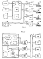
- It is contemplated that the present invention may be implemented in two distinct versions. A first version, hereinafter referred to as the "off-line" version, provides a single user or operator station for creating and revising programmes for a plurality of numerically controlled machines. Generalised data programmes are created at the operator station and the resulting machine control instruction programmes are transferred to a selected numerical control for storage for future recall and use. The operator station includes means for displaying the information and figures associated with programme creation and revision but does not display numerical control input data of a selected machine as the machine instruction programme is executed. A second alterantive version, hereinafter referred to as the "on-line" version, integrates the means for creating and revising programmes with a single numerical control. In the on-line version, a single CRT is used for selectably displaying the normal numerical control display data and the graphic representation displays for programme creation and revision.
- The hardware configuration of the off-line version of the present invention shall be described with reference to Figure I. Machining centres 32 through 38 are shown connected to their
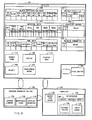
numerical controls 16 through 22. The machining centres perform machining operations upon a workpiece by effecting relative motion between machine members to which the workpiece is mounted and machine members carrying a tool. Thenumerical controls 16 through 22 typically use minicomputers and/or microprocessors to process a numerical control programme to control the member motions ofmachines 32 through 38. Numerical controls 16 through 22 are connected through theirrespective interfaces 24 through 30 tocomputer 10 through itsinterface 12 by the connectingcable 14. Theinterface 12 andcable 14 also permit connection of other devices such astape punch 48. Up to sixteen different machines may be connected to computer 10 'bycable 14. Generalised data programme creation and revision are effected at the operator station comprised ofcomputer 10 and peripheral equipment. Thecomputer 10 includes a processing unit and random access.fuemory for programme execution. A nonvolatile bulk store such as the fixeddisk 46 is used for permanent programme and data storage. The computer provides input and output devices for use by an operator including thedisplay 42 such as for example, a colour cathode ray tube which is controlled by agraphics controller interface 40. The operator makes alphabetic and numeric entries bykeyboard 44. Atape punch 48 is provided for producing hard copies of the machine control programme. All computer programmes required to create and revise the generalised data programme are recorded in thebulk store 46 ofcomputer 10. Generalised data programmes are stored onbulk store 46 and machine control instruction programmes produced therefrom are transferred to the controls throughinterface 12 and overcable 14. Unique data for each machine and control combination including machine parameters and tool data are retained at thecontrols 16 through 22 and transferred through the connectingcable 14 and interfaces tocomputer 10 as required for processing of the generalised data programme to produce a machine control programme. - The hardware configuration of the on-line version shall be described with reference to Figure 2. A general purpose
digital computer 50 is connected to the machinecontrol system bus 52 by connectingcable 54 joiningcommunications interface 58 to the computer serial interface 56. As shown in Figure 2, the numerical control system bus provides a common connection for thecontrol system memory 60, thecentral processing unit 62, theservomechanism control circuits 64,machine interface circuits 66 andcontrol interface circuits 68. An operator station comprises thecolour monitor 70, akeyboard 72 andcontrol push buttons 74. The colour monitor 70 is controlled byinterface controller 76. Thekeyboard 72 andcontrol push buttons 74 are commonly controlled by theoperator station.controller 68. To provide selectable display of numerical control data and the programme creation and revision displays,interface 76 receives input data throughselector 78 which is connected to the graphics controller 80 withincomputer 50 and to thedisplay interface 82 connected to controlsystem bus 52.Control system memory 60 is used to store tool data signals and machine parameter data signals as well as an active machine control programme and the machine control operating system programmes.Computer 50 is equipped with a bulk storage device such asdisk store 84. All programmes required for creation and revision of generalised data programmes are stored inbulk store 84. Further, generalised data programmes and inactive machine control programmes are retained onbulk store 84. As the programme creation and revision system is integrated with the numerical control, no provision is made for selecting from a plurality of machine and control combinations or directing transfer of data to or from a plurality of machine and control combinations. Machine parameter data signals and tool data signals are transferred tocomputer 50 frombus 52 throughcommunication interface 58 and overcable 54. Machine control instruction block signals of a selected machine control programme are transferred frombulk store 84 tomemory 60 overcable 54 and throughinterface 58. One further contrast between the on-line and the off-line versions is in the display device. Asingle colour monitor 70 in the on-fine version is shared to display numerical control data and the graphic representations associated with creation and revision of the generalised data programmes. The off-line version does not display numerical control data normally presented at the machine controls. Rather, a seperate display device is provided for the programme creation and revision station. - The present invention provides for the creation and revision of numerical control programmes in two distinct stages. The first stage produces a generalised data programme consisting of programme blocks as described in Table I. The generalised data programme is subsequently processed to produce the machine control programme comprising machine control instruction blocks as described in Table 2. The system components used to produce and process the generalised data programme shall be described generally with reference to the block diagram of Figure 3.
- The generalised data programme creation and revision is carried out under the control of a
graphics editor programme 100. Processing of the generalised data programme to produce a machine control programme is performed in accordance with acompiler programme 102. Data which is required to produce the machine control programme but which is not supplied by the generalised data programme is obtained from the system files 104. - The
graphics editor programme 100 responds to operator inputs to effect execution of a display screen subroutine selected from thedisplay screen library 106. A selected display screen subroutine provides the data input to the graphics controller to produce the desired image on the operator's station display device. To assist the operator's understanding of the description of the workpiece as the generalised data programme is being created or revised, a current graphical representation of the workpiece is displayed. The data for creating this workpiece display are stored in aworkpiece image buffer 108. As the workpiece feature elements are combined, blend points between linear and circular segments are calculated using an algorithm selected from a display geometrysubroutine library I 10. Block type word signals and data word signals for each block of the generalised data programme are produced in response to operator data entry associated with a single selected display. In this fashion, a complete generalised data block can be created or revised while a single display screen is presented to the operator on the display device. Thegraphics editor programme 100 defines the sequence in which screen displays are presented. This in turn, defines a sequence in which blocks of the generalised data programme are produced. The block type word and data word signals are stored in the sourceprogramme file space 112 in the order in which they are produced. All text to be displayed on the system display device is stored in thedisplay text file 114. A display screen subroutine selected from thescreen library 106 retrieves the required textual display signals from thedisplay text file 114 and passes these data signals to the display controller. - The
compiler 102 verifies the generalised data programme blocks for completeness and data value ,ranges and effects the execution of cycles from thecycle file 124 to produce the machine control instruction block signals which are stored in theobject file 126. Cycle execution is controlled by aninterpreter programme 122. - The cycle routines stored in
cycle file 124 include a mixture of cycle statement signals and variable machine control instruction block signals. The cycle statement signals represent cycle words as described in Table 3. Cycle statements are used to evaluate variables to produce values for output in the machine instruction blocks. The cycle variable value signals are stored in the interpretervariable array 128. Cycle statements must conform to a limited number of predefined forms. Execution of cycle statements is carried out by theinterpreter 122 usinginterpreter template subroutines 132. Selection of the appropriate interpreter template subroutine is accomplished by iterative comparison of a cycle statement against a selected -statement template from the collection ofstatement templates 130. - As hereinbefore stated, the compiler verifies data contained in the generalised data programme blocks. As each generalised data programme block is read by the compiler, the block data word signals are compared against verification data signals retrieved from the block verification data file 140. In this manner the compiler is able to determine whether or not required words are present, whether or not data values are within predefined limits, and provide default values for data words which are not required and are not programmed. The verification data file includes maximum, minimum and default values for both inch and metric dimensions.
- Following verification of all blocks of the generalised data programme, the compiler proceeds to call for the execution of
block type subroutines 120. The block type subroutines effect the completion of block data either by calculation according to predefined algorithms relating programmed data or by retrieval from the appropriate files. For example, the material data file 142 which relates machining operations, material types and feed rate, spindle speed, and coolant control data, can be used by the compiler to supply feed rate, spindle speed, or coolant control data which was not specified in a generalised data block. In a similar fashion the tool data file 144 provides tool specification including the tool assembly identification, the tool loading and unloading status, the tool length and diameter, the tool cycle time limit, tool type, required direction of rotation, tap pitch, and flute angle. By comparing specified data from generalised data programme blocks against the data in the tool data file 144, thecompiler 102 may select a tool location and/or tool assembly for a tool resident at the machine that meets the requirements specified in the programme block. - Likewise, the
compiler programme 102 can effect completion of generalised data blocks by reference to thecompiler control file 146, themachine parameter file 148, or the feed andspeed definition file 150. Themachine parameter file 148 provides data describing machine axis limits, spindle speed limits, available coolant control and other machine parameter data unique to a specified machine. Thecompiler control file 146 includes default and decision data used by thecompiler 102 to control execution of compiler routines. The compiler provides for specification of feed rate in a plurality of dimensional definitions including inch and metric units per unit time, per unit spindle revoloution or per unit tool cutting edge. Spindle speeds may be specified dimensionally as revolutions per unit time or surface feet per unit time. Thecompiler 102 refers to the feed rate and spindle speed definitions given in thedefinition file 150 to assign the proper dimensional definition to programme data. - To permit creation and revision of control programmes for a plurality of machines, the compiler has access to a
machine default file 152 which identifies a file number for each of the filetypes including files machine default file 152 provides the means for selecting a set of cycles for a selected machine from a plurality of sets of cycles. - Both the tool data file 144 and the
machine parameter file 148 can be automatically loaded to thecomputer 10 from a selected numerical control. Thesource file 112 and object file 126 are loaded by execution of thegraphics editor programme 100 and thecompiler programme 102, respectively. The material data file 142, thedisplay text file 114, thecycle file 124, the feed andspeed definition file 150 and themachine default file 152 may all be filled by. signals produced by manual data entry through the operator station by means of afile editior programme 154. - The graphicseditor is the preferred device for creating and revising generalised data programmes. Nevertheless, such programmes may be created without use of a graphic display station provided that the generalised data blocks conform to the definitions set forth in Table I below:
-


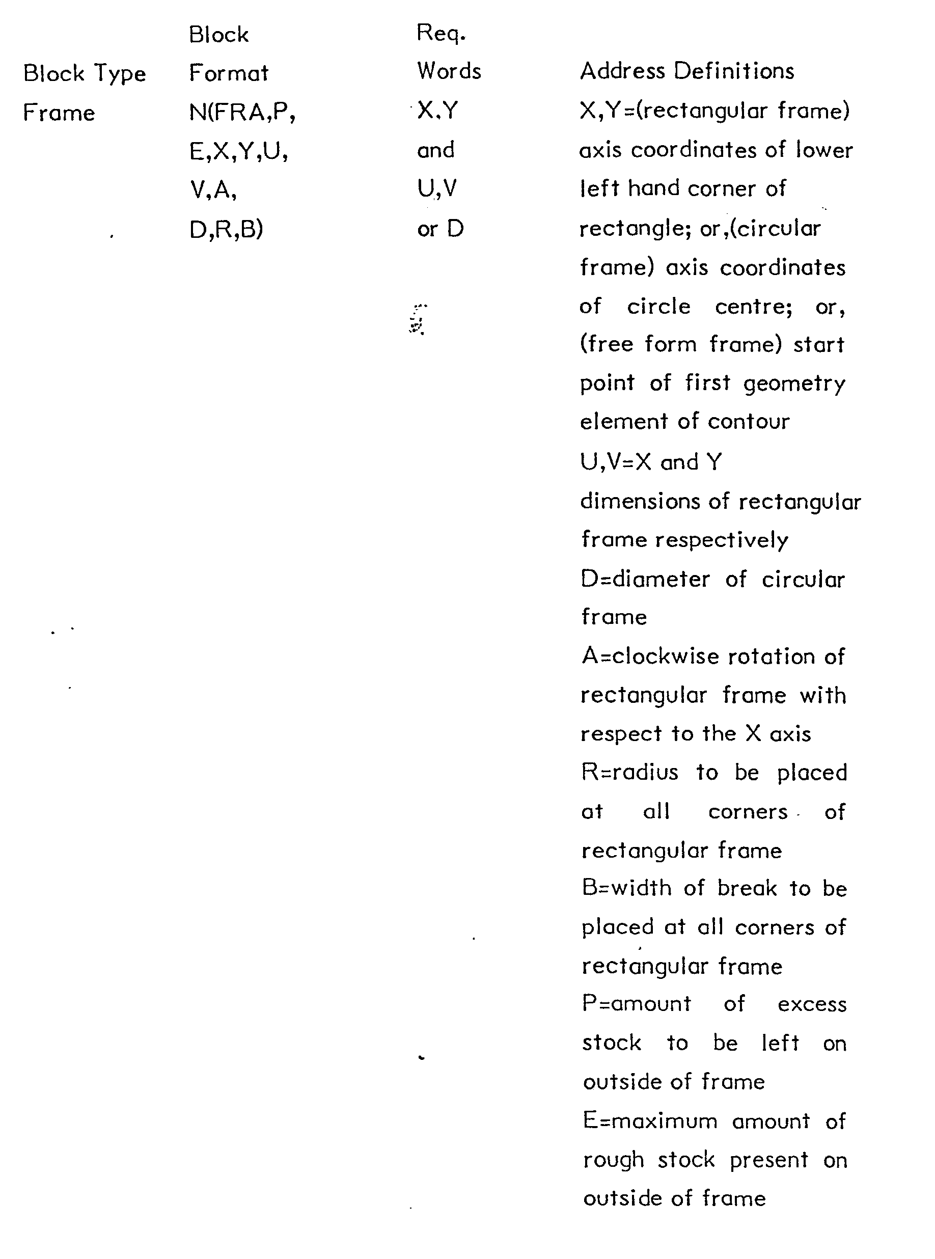

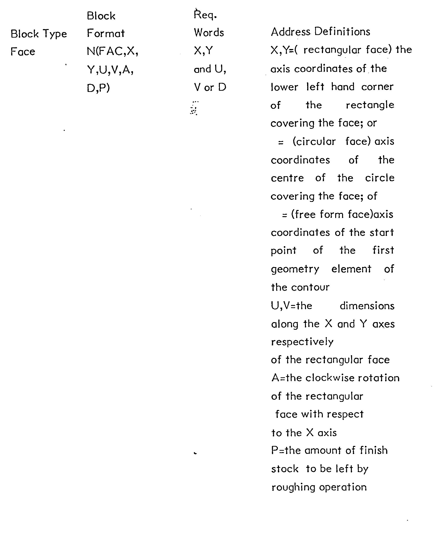


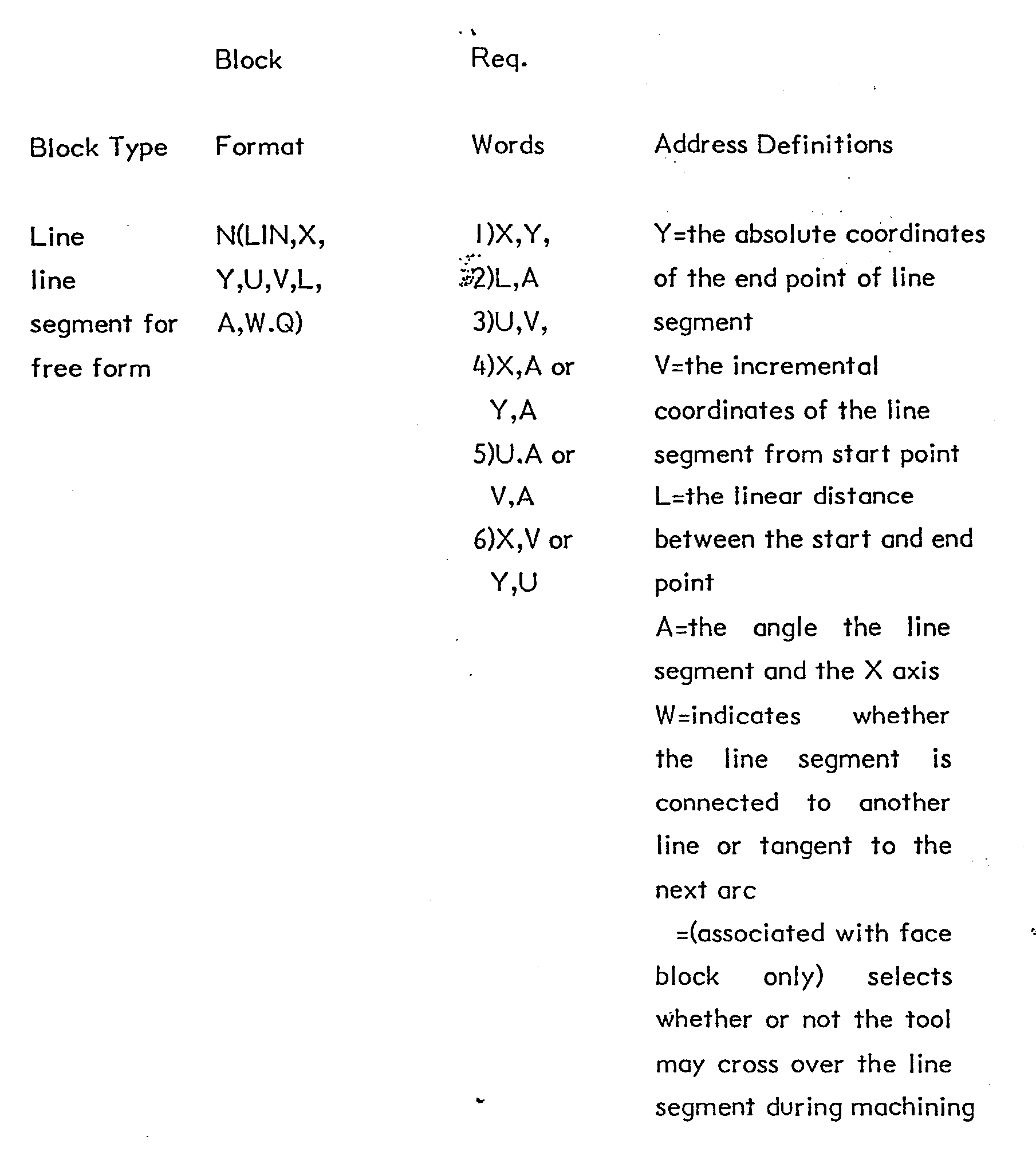


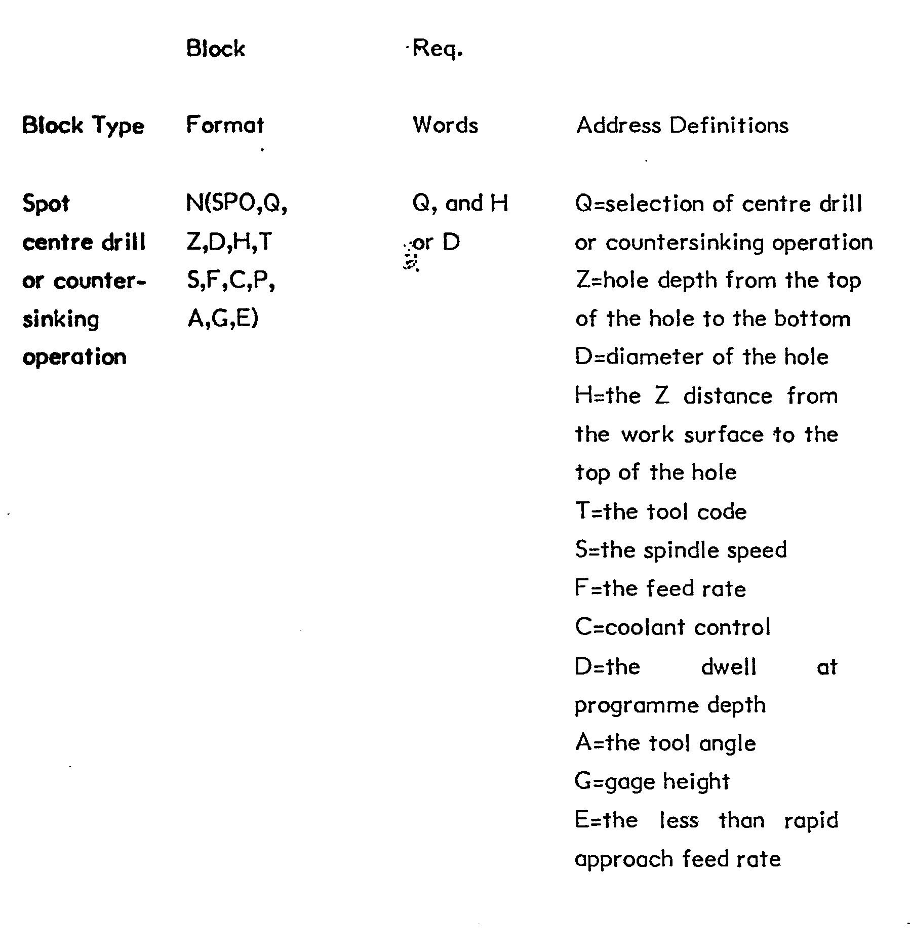

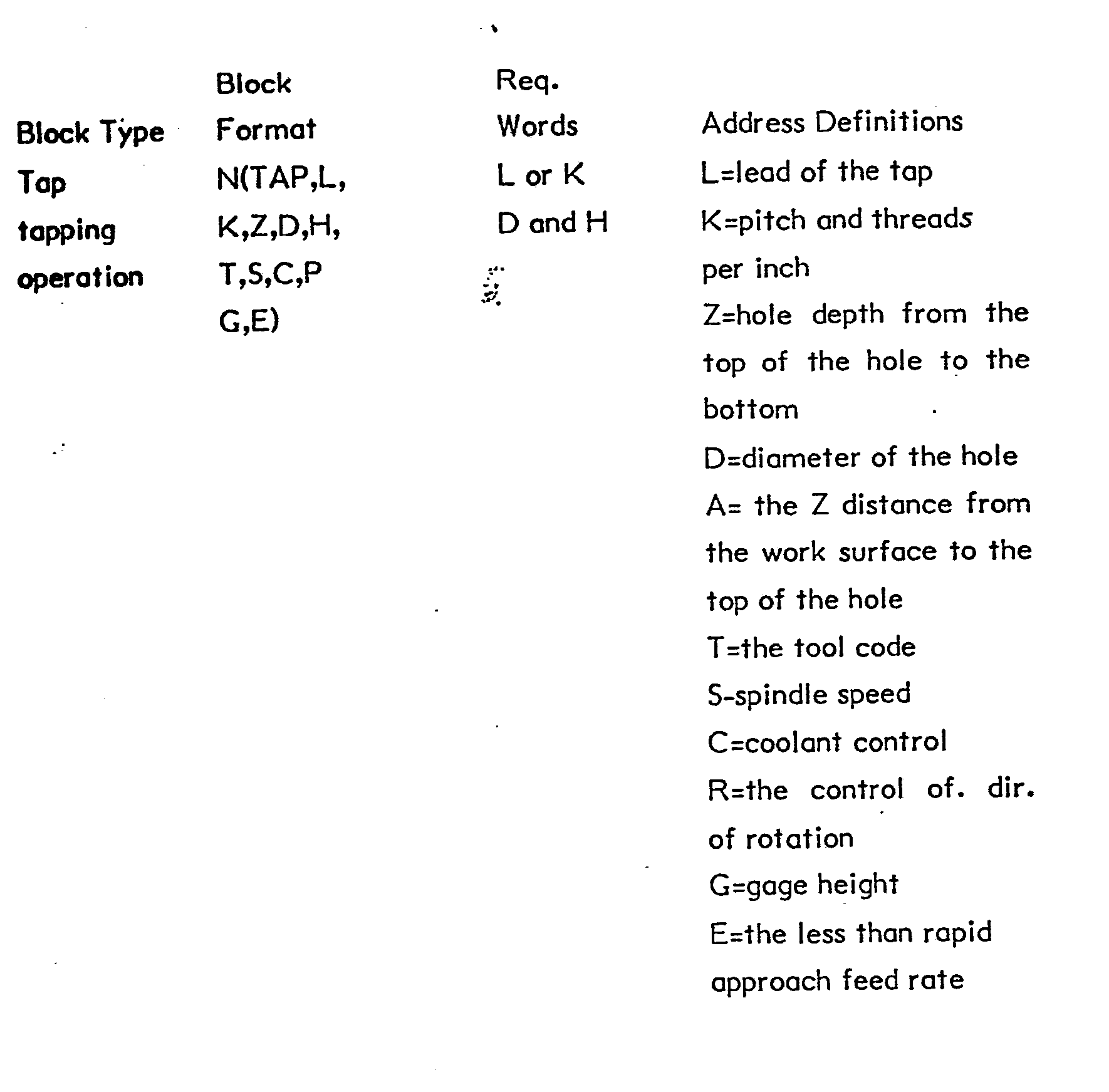


- As illustrated by the Block Format information in Table l, each word of a generalised data block with the exception of the block type is identified by a single letter address. The address N designates a sequence number and is automatically supplied by the
editor programme 100. The remaining alphanumeric words of the generalised data blocks are set forth within the opening and closing parenthesis. Parenthetic block programming is recognised under EIA RS 274-D and classified as Type I I btocks. The numeric data format for the generalised data block words has not been set forth in Table I in the interest of clarity. It will be appreciated by those skilled in the art that each word except the three alphabetic character block type word, begins with its alphabetic address and is followed by one or more numeric characters. The alphabetic address selection and the numeric character selection are a, matter of design choice. Theeditor programme 100,compiler programme 102 andinterpretor programme 122 all conform to a selected definition of the signficance of numeric data for each word of each block type. - The required words of the generalised data programme blocks are readily supplied from the workpiece design data as may be presented on a workpiece drawing. Additional data which is necessary for producing the machine control programme is readily supplied from known tool data or from machining handbooks. The programme structure using the generalised data programme blocks requires that a material selection be specified first then setup data and then a workpiece feature and the associated machining operations for that feature. The
graphics editor programme 100 imposes this sequence on the user during programme creation. - An overall flow chart describing the procedure for creating or revising a generalised data programme shall be described with reference to Figure 4a. At
step 200 the workpiece material is defined. This may be accomplised by identifying the material type and grade. Material specification will result in the creation or revision of a single MATerial block. Atprocedure step 202, a work surface is defined by the dimension in the Z axis to the desired work surface. Atprocedure step 204, a workpiece feature is defined either by specifying data for a predefined feature type such as a. frame, pocket or hole pattern or by programming a series of blocks defining a free-form feature. When the feature definition is complete, machining operations are selected atprocedure step 206. The machining operations comprise all of the operations required to complete a particular feature. Atdecision step 208, it is determined whether or not the feature for which machining operations have been defined is the last feature of the workpiece programme. If not, procedure steps 204 and 206 are repeated until a complete definition of all of the features and the associated machining operations has been completed. After completing the definition of the features,decision step 210 determines whether or not the current work surface is the last work surface for the workpiece programme and if not, a new work surface is defined by the path from the NO side ofdecision step 210 toprocedure step 202. Fromstep 202, programming continues through the procedure steps 204 and 206 anddecision step 208 for definition of all the features of the last defined work surface. When all the work surfaces and features have been defined, the programme task is complete and the last block type indicating end of programme is added as indicated at terminal 212. - The operation of the graphics editor programme shall be described - with reference to the flow chart of Figure 4b. At
process step 220 variable data and programme execution control flags are initialised. Atprocess step 222 the subroutine for controlling display of an initial display screen (predetermined display format) is recalled from thescreen library 106. Atdecision step 224 it is determined whether or not the operator has made a menu selection. In general, menu selections identify a particular field in the display for data entry or a block type requiring display of a different display screen. It is convenient to consider each display screen as defining a state of the operator's station. While the station is in a particular state data entry is performed by the operator to produce data for the associated generalised data programme block. Once the operator has finished with all data entries desired for the current display, a new display and associated state are selected by terminating the current state or by menu selection. - If during display of the initial screen no menu selection has been made,
decision step 226 determines whether or not a terminate input has been produced. If not the editor idles while waiting for the selection of a menu item or the termination of the current system state. If the terminate input signal is recognised, execution of the editor programme proceeds to processstep 228 where the source programme being created or revised by the editor is transferred to thesource programme file 112. Thereafter, the editor function is exited byterminal 280. - If at
decision step 224 it had been determined that a menu selection has been made, execution proceeds to processstep 230 where the display pointer for recalling a selected subroutine from thescreen library 106 is set to the appropriate value indicated by the menu selection. Atprocess step 232, the display screen indicated by the pointer is displayed. Atdecision step 234, it is determined whether or not a menu selection has been made from the currently displayed screen. If a menu selection has been made,decision step 236 determines whether or not data entry is required for the item selected. - If data entry is required, editor programme execution proceeds to
decision step 238 where it is determined whether or not the enter input has been received. The operator's data entry may be loaded to the selected source programme buffer by activation of the enter input. Alternatively, the operator may choose to cancel a data entry and retry. If the enter input has not been received, editor programme execution proceeds todecision step 250 where it is determined whether or not the cancel input has been received. If the cancel input is received, execution proceeds atprocess step 252 where the data entered is cleared from the selected field and thereafter editor programme execution continues through the onpage connector 3 to processstep 238. - If the cancel input is not received, a test is made at
decision step 270 to determine whether or not the terminate input has been received. Termination of the present state of the operator station advances editor programme execution to processstep 272 where the display screen pointer is set to the appropriate value to return to the preceding system state. Thereafter, execution of the editor programme continues through the on page connector I to processstep 232 where the display screen identified by the pointer is displayed. If atdecision step 234 it is determined that no menu selection is made, execution continues atdecision step 270 to determine whether or not the terminate input has been received. If following decision steps 238, 250 and .270 it is determined that data entry has not been completed or cancelled and the current operator station state has not been terminiated, execution proceeds through the sequence of steps begining withdecision step 238 until the enter, cancel or terminate input is received. - In some instances, following a menu selection, an alternative display screen may be required. Thus, at
decision step 236 if no data entry is required, execution of the editor programme proceeds todecision step 256 where it is determined whether or not a new display screen is required. If so, the display screen pointer is set to the appropriate value atprocess step 260 and thereafter execution continues throughprocess step 232 to display a new display screen. If it is determined atdecision step 256 that a new display screen is not required, and keeping in mind that data entry is not required, the appropriate response is to update the display to highlight a field identified by the menu selection. This updating is accomplished atprocess step 258. Thereafter, execution would continue atdecision step 238 awaiting entry of data for the newly highlighted field. - Upon receipt of the enter input signal, as determined by
decision step 238, execution of the editor programme proceeds to processstep 240 where the entered data is loaded from the display field to the word in the editor buffer. Atdecision step 242 it is determined whether or not a new display is required in response to data having been entered. If not, the display will require updating and this is accomplished atprocess step 246. Where data is entered defining features, the result may affect theworkpiece image 108 and may require execution of a mathematical algorithm to complete the definition of the displayed geometry using a subroutine from thegeometry display subroutines 110. Thereafter, editor programme execution proceeds through the on page connector to processstep 232. If it is determined atdecision step 242 that a new display is required, the display pointer is set to the appropriate value atprocess step 244 and execution of the editor programme proceeds through the on page connector to processstep 232. - In general the editor programme provides for the selection of items by the operator through a dispayed menu and the entry of numeric data for a selected data field. The operator advances through the programming procedure described with reference to Figure 4a as permitted by the editor programme primarily by menu selection. That is, the editor programme controls the order in which different display types and, hence, block types can be accessed. Completion of the programming function is indicated by producing the terminate signal input while the initial display screen is displayed. Programme blocks existing in the editor buffer prior to the receipt of the terminate input during display of the initial screen are transferred from the editor buffer to the
source file 112. - An existing generalised data programme may be revised using the procedure of Figure 4b and executing the
graphics editor programme 100 as described with reference to Figure 4b by first specifying the identification of the programme to be revised. The identified programme is recalled from bulk memory and loaded to the editor buffer. The initial display screen is presented and revision of the programme proceeds with the desired menu selections and data entry. - During the creation or revision of a generalised data programme the graphics editor programme displays the features defined with respect to the selected workpiece surface. A satisfactory display of the relevant workpiece geometry is thus effected in two dimensions. As feature block types are selected, the display provides insets depicting the particular feature type. Free-form geometry is contructed in the order in which the geometry elements are specified by the operator. Displays associated with selected machine operations include a two dimensional representation of the tool and its relation to the workpiece surface and an isometric representation of the geometry which the tool is intended to produce.
- A generalised data programme is converted to a machine control programe by execution of the
compiler programme 102. The machine control programme will in general conform to the EIA standard RS 274. This standard permits relatively wide latitude with respect to the type I block definitions and the resulting machining functions. An abbreviated description of the type I programme blocks is set forth below in Table 2:
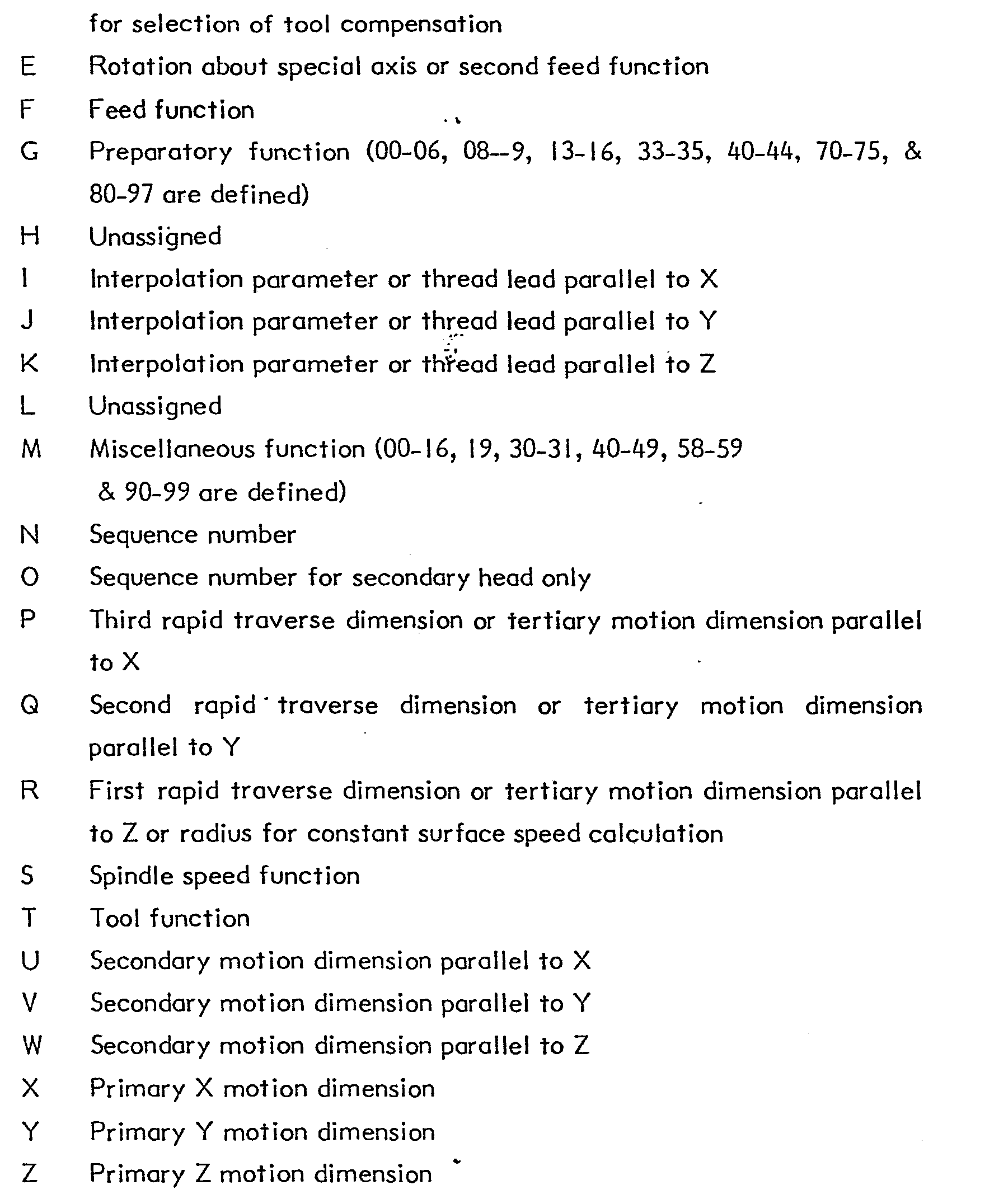
- Numeric data format for each word of Table 2 is defined by the designer of the numeric control. In general, motion dimensions are programmed with a sign, plus or minus, to indicate the direction of travel. Decimal point programming is permitted but not required. Dimension data directly specifies machine axis motion. Preparatory functions in the range of 81-89 identify "fixed cycles" defined by the control designer. A fixed cycle typically causes the control to respond to the data input with a predefined sequence of motions to perform a machining operation. Other preparatory functions are used to select types of interpolation, interpolation planes, cutter compensation and inch or metric programme input. Miscellaneous functions effect selection of spindle rotation direction, coolant control, tool changes and gear changes. And, as in the case of preparatory functions, the control designer determines the specific machine response to a programmed function code.
- From Table 2 it is is apparent that the machine control instruction blocks specify machine member motion relative to the machine control programme coordinate system. The specific tool motion to result from the generalised data programme blocks is a function of the preference of the machine tool builder and the feature geometry and therefore is determined by the design of the
cycles 124. It is the function of the compiler to use the data definitions of the generalised data programme blocks to provide data required for the execution of thecycles 124 to produce the machine control blocks conforming to the description of Table 2. - Operation of the compiler will be described with reference to the flow chart of Figure 5. Beginning at
process step 300, variable values and execution control flags are initialised. Atprocess step 302, the file storage spaces are loaded with data recalled either from the bulk store or from the machine control. Atprocess step 304, a generalised data programme block is read by thecompiler programme 102.Process step 306 executes a verification subroutine to compare each word of the generalised data programme block read atprocess step 304 against the appropriate block verification data from theblock verification file 140. Atdecision step 308 it is determined whether or not the programmed block data is within the limits specified by the verification data and all required data words of the block type are present. If not, an error signal is output atprocess step 310 and execution of the compiler programme is terminated at the terminal 311. - Provided that
decision step 308 determined that the programmed data of the block was satisfactory, execution of the compiler programme proceeds atprocess step 312 where the generalised data block is transferred from a temporary buffer used by the compiler to permit input of the next generalised data programme block. If the verified block was an END block as determined by"decision step 314, all blocks of the selected generalised data programme would have been read and verified and execution of the compiler programme can proceed atprocess step 316. Untildecision 314 determines that a verified block is an END block, execution of process steps 304 through 312 is repeated as indicated by the loop from the NO side ofdecision step 314. - Assuming the programme input and verification phase of the compiler is successfully completed, the next processing function is initiated by setting a block pointer* to the first block of the generalised data programme at
process step 316. At process step 318 a block type subroutine is called to complete the block data. The block type subroutine may be required to supply data from the material data file 142 or the tool data file 144 in place of omitted words in the programme block. For example, the operator need not specify feed rates and spindle speeds for the selected machine operations provided the identified material is one for which material data signals exist in the material data file. Thus, the subroutine called atprocess step 318 would provide the missing information based on the selected machining operation and the identified workpiece material. Alternatively, the block type subroutine may be required to produce coordinate values for use by the interpreter using one of the alternative input specifications for locations. For example, the grid hole pattern block permits specification of the location of holes in terms of incremental spaces from the first hole. The block type subroutine would then use the data available in the generalised data programme block to produce the rectangular coordinates of all of the holes in the grid pattern. - Upon completion of execution of the block type subroutine, data is loaded into the
variable array 128 byprocess step 320. Thereafter, the cycle code fromcycle store 124 is loaded from the bulk store to the active computer memory for execution under control of the interpreter. Atprocess step 324, the interpreter subroutine is called to effect execution of the cycle code loaded inprocess step 322. Upon completion of execution of the cycle code, execution of the compiler programme resumes atdecision step 326 where it is determined whether or not the last generalised data programme block processed was the END block. If not, the pointer is incremented to the next block in the generalised data programme atprocess step 328 and'execution of the compiler programme continues through onpage connector 2 to processstep 318. If it is determined atdecision step 326 that the last generalised data programme block processed is the END block, the resultant machine control blocks are transferred to theobject file 126. Thereafter, execution of the compiler programme is exited atterminal 332. - It will be noted from the description of the flow chart of Figure 5 that following verification of the generalised data programme block, the compiler's functions are resolved into two primary operations. First, the compiler effects the execution of the block type subroutine and thereafter effects execution of the interpreter to process the appropriate block type cycle. Figure 6 is a flow chart of the general process associated with execution of the block type subroutine.
- Referring to Figure 6, it is determined at
decision step 330 whether or not any calculation is required for the block type. If no calculation is required, execution proceeds atdecision step 332 when it is determined whether or not any addresses have been omitted from the programme block. It is to be kept in mind that having verified the block, the absence of option words only is determined bydecision step 332. If no optional words were omitted, no additional processing is required, and the execution of the block type subroutine is ended and resumption of execution of the compiler programme is effected through the return of terminal 338. If atdecision step 332, it is determined that option words have been omitted from the generalised data programme block the required words are supplied with data from the appropriate file. - If it had been determined at
decision step 330 that the block type requires a calculation, the approprfate calculation subroutine is called atprocess step 336. Thereafter, resumption of the overall processing of the compiler programme is effected by the return through terminal 338. - To describe the operation of the interpreter, it will be necessary to describe the structure of the cycles which are executed under the control of the interpreter. In general, the cycles comprise cycle statements including cycle words and variables in the form and format set forth below in Table 3. Further, the cycles include variable machine control instruction blocks with cycle variables in place of fixed constants. The cycle variables in the variable machine control instruction blocks are ultimately replaced by numeric values produced by the execution of the cycle statements. The interpreter effects execution of the cycle statements to evaluate the variables therein and the variables embedded in the machine control blocks and ultimately transfers the machine control instruction blocks with the appropriate numeric data to the
object file 126. Cycle statements provide flow control through the cycle as well as logical and arithmetic operations to effect evaluation of variables. Cycle word types and their descriptions are set forth in Table 3 below:
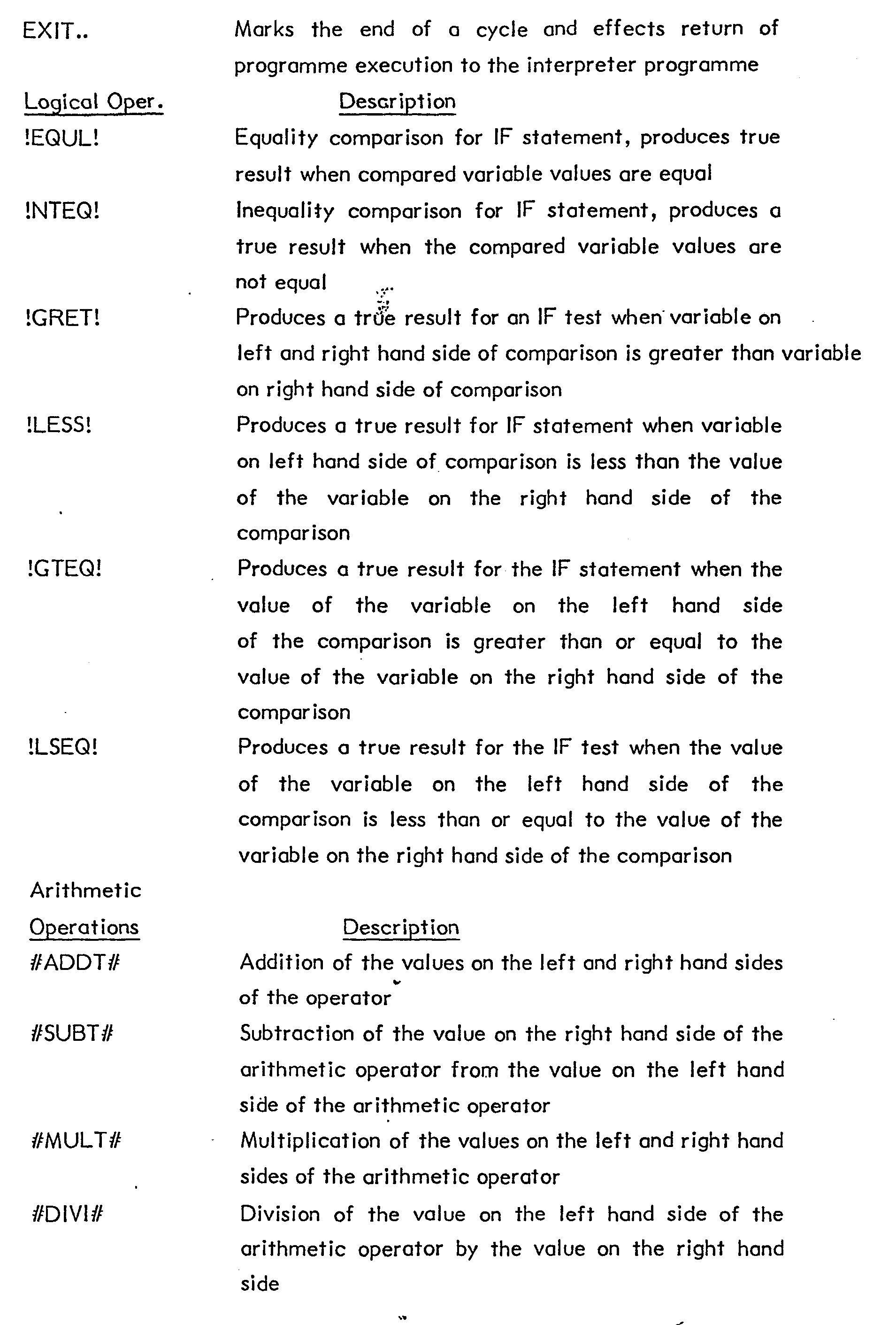

- As noted hereinbefore, the cycle statements are intermixed with variable numerical control instruction blocks wherein certain of the block word values are represented by cycle variable names. Evaluation of these variables is accomplished by execution of the cycle statements. The numerical control instruction blocks are output to the
object file 126 with the value for these block words" in place. The flow control type statements of the cycle are permitted a limited number of forms. Specifically, IF statements are permitted two forms: IF GOTO and; IF THEN ELSE. The GOTO statement is permitted two forms; either conditionally when incorporated in an IF statement or. unconditionally when not. The REPEAT statement may be written in a simple form without an embedded REPEAT statement or it may be written in a compound form where a second REPEAT statement is embedded within the code making up the section to be repeated. Variable statements are permitted in five forms: an equality with a single value, an equality involving a simple expression having a single arithmetic operation, an equality involving a compound expression having two arithmetic operations, a subscript or counting variable being set equal to a numeric constant and a subscript or counting variable being set equal to an expression including an index variable an arithmetic operation and a numeric constant. - The execution of cycles accomplished under control of the interpreter programme. Operation of the interpreter shall be described with reference to the flow chart of Figure 7. At
process step 350, interpreter pointers and process control flags are initialised. Atprocess step 352, the next cyle statement is read by the interpreter. Following initialisation byprocess step 350, the statement read by process step 353 is the first cycle statement of the cycle being executed. Atprocess step 354, the cycle statement is parsed into its component words. Atdecision step 356 it is determined whether or not the cycle statement being processed is an EXIT statement. If it is, the execution of the cycle is complete and execution of the compiler programme is continued by the return throughterminal 390. - If the cycle statement being processed is not an EXIT statement, processing of the cycle statement continues at
decision step 358 where it is determined whether or not the cycle statement is a variable machine control instruction block. The numerical control instruction blocks incorporated in the cycle are written with numeric format words to conform the format of the control instruction block words to that required by the numerical control. Atdecision step 360 it is determined whether or not the control instruction block detected bydecision step 358 includes numerical format words. If it does, the format code is saved atprocess step 364. Atprocess step 366 the variable value is retrieved from the variable array and atprocess step 368 the formatted word is loaded to the object buffer. If it had been determined atdecision step 360 that no numerical format codes were present in the control instruction block, process steps 364 through 368 would be skipped and the words of the control instruction block would be loaded to theobject code file 126 byprocess step 362. In either event, following the transfer of the control instruction block words to theobject file 126 the cycle statement pointer is updated atprocess step 386. Execution of the cycle statements then continues through'the onpage connector 2 atprocess step 352 where the next cycle statement indicated by the cycle statement pointer is read. - As has been described, the cycle flow. control statements and variable statements are programmed in a limited number of forms. This limitation facilitates cycle processing by the interpreter which effects execution of cycle statements according to the statement type. To determine cycle statement type, it is only necessary that the interpreter compare the statement form against a permitted form template. Once the statement form has been determined by this comparison procedure, a subroutine for processing the statement can be executed.
- Referring again to Figure 7, it is determined at
decision step 370 whether or not the cycle statement being processed is a process or flow control statement. If it is, the cycle statement is compared against the form templates by the loop comprisingprocess step 372 anddecision step 374 until a match is found. When the match is found between the permitted form templates and the cycle statement being processed, the appropriate cycle template processing subroutine from the collection oftemplate subroutines 132 is called atprocess step 376. As it is the function of the flow control statements to result in evaluation of variables which appear in variable machine control instruction blocks, the flow control statement processing does not result directly in loading of any control instruction blocks to theobject file 126. Upon completion of the execution of the template subroutine, the cycle statement pointer is updated to indicate the next cycle statement byprocess step 386. Thereafter, cycle processing continues to the onpage connector 2 atprocess step 352 where the next cycle statement is read. - Had it been determined at
decision step 370 that the cycle statement being processed was not a process control statement, and keeping in mind that it would have been determined bydecision step 358 that the cycle statement was not a control instruction block, the remaining alternative is that the cycle statement is a variable. This is indicated by thevariable statement terminal 378. Variable statements are also required to conform to a limited number of forms and determination of the form of the variable statement being processed is accomplished byprocess step 380 anddecision step 382 which compare the variable statement to permitted form templates. When a match between the variable statement and a permitted template is determined, the appropriate template subroutine is called byprocess step 384. Variable statements produce values of variables for execution of the arithmetic operations included in the value expressions. The resultant value is stored in the appropriate location within the interpretervariable array 128. Upon completion of-execution of the variable statement template subroutine, processsing of cycle statements continues by updating the statement pointer atprocess step 386 and thereafter resuming execution of cycle statements through the onpage connector 2 to processstep 352. - The last statement of a cycle is the EXIT statement which will be detected by a
decision step 356. Cycle statement processing is terminated by the exit statement and returned to the compiler execution is effected throughterminal 390. - To better illustrate the relationship between a cycle and the machine control instructions, an example cycle shall be described. It will be noted that dimensional data for each control instruction block included in the cycle is preceded by two format codes used to indicate the appropriate format for inch or metric dimensions.


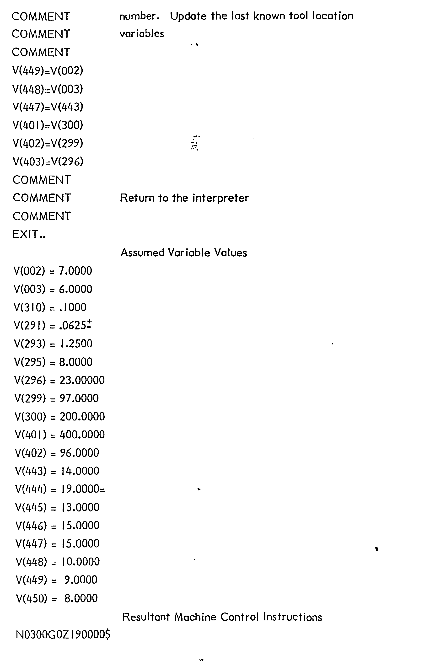

- It will be noted that the foregoing is merely an example of a cycle which would be called for execution by a generalised data programme TAP block. It will be appreciated that a significantly different cycle could be written for the TAP block type.
- It will now be seen that the generalised data programme blocks may readily be written with reference to workpiece design data. These blocks do not in general define specific machine motions. However, they do specify sufficient data to permit the generation of machine motion commands. The conversion of generalised data programme blocks to control instruction blocks depends upon the structure of the cycle relating the generalised data programme block type to desired machine motion definition. Consequently, machine and control combinations having significant differences may nevertheless be used to perform the desired machining operations as directed by the generalised data programme provided that the necessary interpretive cycles are available for conversion of the generalised data programme to machine instruction blocks. The comparative ease of programme revision by a machine operator is a direct consequence of the structure of the generalised data programme blocks to permit data definition using the workpiece design data. The operator performing programme revisions is not required to have specific knowledge as to the appropriate word coding for a specific machine and control combination. Code variations from one machine and control combination to another are readily accommodated by the cycles. Further convenience for the operator is provided by the graphics editor which imposes the necessary programme structure by means of menu control. The operator is thus permitted to provide the required material, work surface, feature, and machining operation data in the appropriate order to achieve the desired workpiece processing.
- While the invention has been described with reference to the preferred embodiment, and while.,the preferred embodiment has been decribed in considerable detail, it is not intended to in any way limit the scope of the present invention to such detail. Rather, it is the intention of applicant that the present invention cover all modifications, alterations and equivalents falling within the spirit and scope of the appended claims.
- It is noted in particular that while the preferred embodiment pertains to milling and drilling operations, an analogous approach could be used for the creation and revision of generalised data programmes for turning operations. Again, a relatively simple two dimensional graphic representation of the profile of the workpiece would suffice for the definition of workpiece features. A variety of feature types generally catergorised as to inside and outside diameters and including tapers, radii, filets, chamfers and necks can then be defined. The workpiece profile may further be defined by inside and outside corners with which selected features are associated. Outside and inside corners are identified moving from the front to the rear of the workpiece and the various available feature types associated with inside and outside turning operations are then selected and specified for each corner. As in the case of milling operations, predefined shapes as well as free-form shapes can be accommodated.
- It will further be noted that while the preferred embodiment has been described with particular reference to its operating environment, other hardware arrangements would be equally suitable. Were sufficient processing capability and memory capacity provided within a numerical control it would not be necessary to require communication between the numerical control system and an independent computer processor. Further, other graphic representations than those suggested herein could be readily adapted for the creation and revision of programmes as described.
Claims (22)
- I. A method for creating and revising programmes for a numerically controlled machine, the numerically controlled machine having movable members responding to control signals produced by a numerical control in response to machine control instruction blocks, the machine and control effecting relative motion between a workpiece and tool to perform machining operations on the workpiece, the method comprising the steps of:a) producing generalised data block signals representing sets of alphanumerical words, each generalised data block having one block type word and at least one data word defining a value associated with the block type, the generalised data block selectably describing a workpiece material, a workpiece surface, workpiece features, and machining operations; andb) producing machine control instruction block signals in response to the generalised data block signals, the machine control instruction block signals representing sets of alphanumeric words describing machine member motion, the machine control instruction block signals conforming to the form and format required by the machine control.
- 2. The method of Claim I wherein the step of producing machine control instruction block signals further comprises the steps of:a) storing cycle signals representing cycle statements and variable machine control instruction blocks, each cycle being associated with a selected generalised data block type and defining a sequence of steps for producing machine control instruction block signals; andb) executing a cycle in response to a selected generalised data block type to produce machine control instruction block signals.
- 3. The method of Claim 2 wherein the cycle statements include comparative and arithmetic expressions relating variables and the step of executing cycles further comprises the steps of:a) producing variable value signals in response to the comparative and arithmetic operation cycle statements; andb) substituting the variable value signals in the variable machine control instruction blocks to produce the machine control instruction block signals.
- 4. The method of Claim I wherein producing generalised data block signals further comprises the steps of:a) identifying a workpiece material type;b) specifying work surface location data defining the location of a work surface upon which machining operations are performed;c) specifying work surface feature data defining characteristics of a feature to be machined in the work surface; andd) specifying machining operation data defining machining operations associated with a specified feature.
- 5. The method of Claim 4 wherein the step of producing machine control instruction block signals further comprises the steps of:a) storing generalised data block verification data signals representing verification data for selected words of the generalised data blocks;b) comparing generalised data block signals representing alphanumeric words of the generalised data block with generalised data block verification signals;c) producing an error signal in response to detecting the absence of words required for the generalised data block type; andd) producing an error signal in response to detecting values of alphanumeric words of the generalised data block beyond limits defined by the generalised data block verification signals.
- 6. The method of Claim 5 wherein the step of producing machine control instruction block signals further comprises the steps of:a) storing material data signals representing spindle speeds, feed rates, and coolant control data associated with selected machining operations in selected workpiece materials; andb) producing the required machine control instruction block values for spindle speeds, feed rates, and coolant control in response to the material data signals and theselected workpiece material.
- 7. The method of Claim 6 wherein the step of producing machine control instruction block signals further comprises the steps of:a) storing tool data signals representing the tool type, tool identification, tool location, tool dimensions, number of tool teeth, and flute angle; andb) producing variable value signals for a machine control instruction block word associated with tool identification in response to the tool data signals and the machining operation data of the generalised data blocks.
- 8. A method for creating and revising programmes for a plurality of numerically controlled machines, each numerically controlled machine having movable members responding to control signals produced by a machine control in response to a programme of machine control instruction blocks, the machine and control effecting relative motion between a workpiece and a tool to perform machining operations on the workpiece, the method comprising the steps of:a) producing generalised data block signals representing sets of alphanumeric words, each generalised data block having one block type word and at least one data word defining a value associated with the block type, the generalised data block selectably describing a workpiece material, a workpiece surface, workpiece features, and machining operations;b) identifying a machine and control for which machine control instruction block signals are to be produced; andc) producing machine control instruction block signals in response to the generalised data block signals and the identified machine and control, the machine control .instruction block signals representing sets of alphanumeric words describing machine member motion, the machine control instruction blocks conforming to the form and format required by the machine control.
- 9. The method of Claim 8 wherein the step of producing machine control instruction blocks further comprises the steps of:a) storing a plurality of sets of cycle signals, the cycle signals representing cycle statements and variable machine control instructions, each cycle being associated with a selected generalised data block type and for producing machine control instruction block signals, and each set of cycles being associated with a machine and control combination;b) selecting a set of cycle signals associated with a machine and control in response to the identification of 'the machine and control for which machine control instruction block signals are to be produced; andc) executing the selected set of cycles in response to generalised data block types to produce the machine control instruction block signals.
- 10. An apparatus for creating and revising programmes for a numerically controlled machine, the numerically controlled machine having movable members responding to control signals produced by the machine control in response to a programme of machine control instruction blocks, the machine and control effecting relative motion between a workpiece and a tool to perform machining operations on the workpiece, the apparatus comprising:a) means for producing generalised data block signals representing sets of alphanumeric words, each generalised 3data block having one block type word and at least one data word defining a value associated with the block type, the generalised data blocks selectably describing a workpiece material, a work surface, workpiece features, and machining operations; andb) means for producing machine control instruction block signals in response to the generalised data block signals, the machine control instruction block signals representing sets of alphanumeric word describing machine member motion, the machine control instruction blocks conforming to the form and format required by the machine control.
- 11. The apparatus of Claim 10 wherein the means for producing machine control instruction block signals further comprises:a) means for storing cycle signals representing cycle statements and variable machine control instruction blocks, each cycle being associated with a selected generalised data block type and for producing machine control instruction block signals; andb) means responsive to the generalised data block signals and the cycle signals for producing the machine control instruction block signals.
- 12. The apparatus of Claim II wherein the cycle statements include comparative and arithmetic expressions relating variables and the means for producing machine control instruction block signals further comprises:a) means responsive to the comparative and arithmetic expressions of the cycle statements for producing variable value signals representing values of variables associated with the words of the variable machine control instruction blocks; andb) means responsive to the variable value signals and the variable machine control instruction blocks for producing the machine control instruction block signals.
- 13. The apparatus of Claim 10 wherein the means for producing generalised data block signals further comprises:a) means for displaying graphic representations associated with selected block types, the graphic representations including identifying characters of words of the generalised data block;b) means for selecting a generalised data block word identification; andc) means responsive to the selected word for producing generalised data block signals representing an alphanumeric word.
- 14. The apparatus of Claim 13 wherein the means for producing machine control instruction block signals further comprises:a) means for storing generalised data block verification data signals;b) means for comparing selected alphanumeric words of the generalised data block with generalised data block verification data signals;c) means for producing an error signal in response to detecting the absence of alphanumeric words required by the generalised data block type; andd) means for producing an error signal in response to detecting a value of a generalised data block alphanumeric word beyond a limit defined by the generalised data block verification signals.
- 15. The apparatus of Claim 14 wherein the means for producing machine control instruction block signals further comprises:a) means for storing machine parameter data signals representing machine member travel limits, spindle speed limits, and spindle power limits;b) means for comparing selected alphanumeric words of the generalised data block signals with machine parameter data signals; andc) means for producing an error signal in response to detecting an alphanumeric word of the generalised data block in excess of the limits defined by the machine parameter data signals.
- 16. The apparatus of Claim 1.5 wherein the means for producing machine control instruction blocks further comprises:a) means for storing material data file signals representing spindle speeds, feed rates, and coolant control data associated with selected machining operations in selected material types; andb) means responsive to the generalised data block signals and the material data file signals for selecting spindle speeds, feed rates, and coolant control data for a selected machining operation in a selected material.
- 17. The apparatus of Claim 16 wherein the means for producing machine control instruction block signals further comprises:a) means for storing tool data signals representing the location, identification, type and dimensions of tools available on a machine; andb) means responsive to the generalised data block signals and the tool data signals for selecting an available tool for a selected machining operation.
- 18. The apparatus of Claim 17 further comprising;a) means for receiving tool data signals from the machine control; andb) means for receiving machine parameter data signals from the machine control.
- 19. The apparatus of Claim 18 further comprising means for transmitting machine control instruction block signals to the machine control.
- 20. An apparatus for creating and revising programmes for a plurality of numerically controlled machines, each numerically controlled machine having movable members responding to control signals produced by a machine control in response to a programme machine control instruction blocks, the machine and control effecting relative motion between a workpiece and a tool to perform machining operations on the workpiece, the apparatus comprising:a) means for producing generalised data block signals representing sets of alphanumeric words, each generalised data block having one block type word and at least one data word defining a value associated with a block type, the generalised data block selectably describing a workpiece material, a workpiece surface, workpiece features, and machining operations;b) means for identifying a machine and control for which machine control instruction block signals are to be produced; andc) means responsive to the machine and control identifying means and the generalised data block signals for producing machine control instruction block signals, the machine control instruction block signals representing sets of alphanumeric words describing machine member motion, the machine control instruction block conforming to the form and format required by the machine control.
- 21. The apparatus of Claim 20 wherein the means for producing machine control instruction block signals further comprises:a) means for storing a plurality of sets of cycle signals,' the cycle signals representing cycle statements and variable machine control instruction block, each cycle being associated with a selected generalised data block type and defining a sequence of steps for producing machine control instruction block signals and each set of cycles being associated with a machine control combination;b) means responsive to the identification of the machine and control for selecting a set of cycle signals; andc) means responsive to the generalised data block signals and the selected set of cycle signals for producing the machine control instruction block signals.
- 22. The apparatus of Claim 21 further comprising:a) means responsive to the identification of a machine and control for receiving from the selected control tool data signals representing the identification, type, dimensions, and locations of tools available on the selected machine;b) means responsive to the identification of a machine and control for receiving from the selected control machine parameter data signals representing machine member travel limits, spindle speed limits, and spindle power limits of the selected machine; andc) means responsive to the identification of a machine and control for transmitting machine control instruction block signals to the selected machine control.
Applications Claiming Priority (2)
| Application Number | Priority Date | Filing Date | Title |
|---|---|---|---|
| US06/646,651 US4636938A (en) | 1984-08-31 | 1984-08-31 | Method and apparatus for producing numerical control programs |
| US646651 | 1984-08-31 |
Publications (3)
| Publication Number | Publication Date |
|---|---|
| EP0177164A2 true EP0177164A2 (en) | 1986-04-09 |
| EP0177164A3 EP0177164A3 (en) | 1986-12-30 |
| EP0177164B1 EP0177164B1 (en) | 1991-01-02 |
Family
ID=24593906
Family Applications (1)
| Application Number | Title | Priority Date | Filing Date |
|---|---|---|---|
| EP85306050A Expired - Lifetime EP0177164B1 (en) | 1984-08-31 | 1985-08-27 | Method and apparatus for producing numerical control programmes |
Country Status (5)
| Country | Link |
|---|---|
| US (1) | US4636938A (en) |
| EP (1) | EP0177164B1 (en) |
| JP (1) | JPS61136104A (en) |
| CA (1) | CA1243380A (en) |
| DE (1) | DE3581037D1 (en) |
Cited By (8)
| Publication number | Priority date | Publication date | Assignee | Title |
|---|---|---|---|---|
| EP0248910A1 (en) * | 1985-12-10 | 1987-12-16 | Fanuc Ltd. | Method of preparing nc data |
| EP0405302A2 (en) * | 1989-06-30 | 1991-01-02 | Siemens Aktiengesellschaft | Operation method of a numerically controlled machine |
| EP0435215A1 (en) * | 1989-12-25 | 1991-07-03 | Mazda Motor Corporation | Method of simulating a sequential control program |
| EP0515699A1 (en) * | 1990-12-18 | 1992-12-02 | Fanuc Ltd. | Instruction method for robot operation program |
| EP0544073A2 (en) * | 1991-09-17 | 1993-06-02 | Mitsubishi Denki Kabushiki Kaisha | Numerical control unit |
| EP0593772A1 (en) * | 1992-03-19 | 1994-04-27 | Fanuc Ltd. | Nc data preparing system |
| US5485552A (en) * | 1990-12-18 | 1996-01-16 | Fanuc Ltd. | Method of creating a robot motion program |
| CN112846886A (en) * | 2020-12-31 | 2021-05-28 | 广州科源数控科技有限公司 | Hole site positioning method of machine tool based on graphic file |
Families Citing this family (30)
| Publication number | Priority date | Publication date | Assignee | Title |
|---|---|---|---|---|
| US4972322A (en) * | 1984-09-21 | 1990-11-20 | Brother Kogyo Kabushiki Kaisha | Method for preparing numerical control data for a machine tool |
| US4843566A (en) * | 1986-03-07 | 1989-06-27 | Hewlett-Packard Company | Robot motion control system |
| US4835730A (en) * | 1987-02-27 | 1989-05-30 | Adept Technology, Inc. | Database driven robot programming system and method |
| JPS63223869A (en) * | 1987-03-13 | 1988-09-19 | Hitachi Ltd | Program producing method |
| JPS6462704A (en) * | 1987-09-02 | 1989-03-09 | Fanuc Ltd | High speed working system |
| JPS6462706A (en) * | 1987-09-03 | 1989-03-09 | Fanuc Ltd | Nc program output system |
| US4887221A (en) * | 1987-09-25 | 1989-12-12 | Sunnen Products Company | Computer controlled honing machine using look up table data for automatic programming |
| US4912625A (en) * | 1987-09-30 | 1990-03-27 | The Boeing Company | Graphics verification system for numerical control programs |
| JPH0283141A (en) * | 1988-09-20 | 1990-03-23 | Mitsubishi Electric Corp | Numerical control device |
| WO1990008988A1 (en) * | 1989-01-25 | 1990-08-09 | Hitachi, Ltd. | Method and apparatus for automatically generating control program for computer controlled systems |
| US5239476A (en) * | 1991-04-02 | 1993-08-24 | Strippit, Inc. | Multi-level state language controller for multi-threaded machine control |
| JPH05282021A (en) * | 1992-03-31 | 1993-10-29 | Fanuc Ltd | Machining condition generation system for nc machine tool |
| US5485620A (en) * | 1994-02-25 | 1996-01-16 | Automation System And Products, Inc. | Integrated control system for industrial automation applications |
| US5444634A (en) * | 1994-04-28 | 1995-08-22 | Illinois Tool Works Inc. | Lubricant nozzle positioning system and method |
| US5465215A (en) * | 1994-07-07 | 1995-11-07 | Cincinnati Milacron Inc. | Numerical control method and apparatus |
| EP0751447B1 (en) * | 1995-06-26 | 2001-12-19 | Siemens Aktiengesellschaft | Numerical control method |
| JPH09325804A (en) * | 1996-06-06 | 1997-12-16 | Toshiba Mach Co Ltd | Automatic nc program generation device for roll machining |
| JP3347964B2 (en) * | 1997-01-17 | 2002-11-20 | 三菱電機株式会社 | Automatic programming device and method |
| DE19834863A1 (en) * | 1998-08-01 | 2000-02-03 | Heidenhain Gmbh Dr Johannes | Method for secure data transmission between a numerical control and a spatially separated device |
| DE10034079A1 (en) * | 2000-07-13 | 2002-01-24 | Heidenhain Gmbh Dr Johannes | Device and method for controlling a machine tool |
| US6772042B1 (en) | 2001-05-14 | 2004-08-03 | Dimensional Control, Inc. | Programmable coolant nozzle system |
| CA2451275C (en) * | 2001-07-25 | 2008-02-12 | Lhr Technologies | Processor-controlled carving and multi-purpose shaping device |
| US7016745B1 (en) * | 2004-12-21 | 2006-03-21 | The Boeing Company | NC programming and predetermined practices integration |
| EP2058717B1 (en) * | 2007-11-12 | 2011-07-20 | Siemens Aktiengesellschaft | Method and device for operating a machine tool |
| CN101870072A (en) * | 2009-04-21 | 2010-10-27 | 鸿富锦精密工业(深圳)有限公司 | Drilling machine compiler |
| US8244386B2 (en) * | 2009-10-08 | 2012-08-14 | Hurco Companies, Inc. | Machine tool system control having automatic safe repositioning |
| US10705507B2 (en) * | 2014-11-07 | 2020-07-07 | Nuovo Pignone Srl | Method for generating a machining program and machine tool |
| CN107807824A (en) * | 2017-11-01 | 2018-03-16 | 南通欧科数控设备有限公司 | A kind of operation method of autocoding engraving program |
| US10543598B2 (en) * | 2018-02-26 | 2020-01-28 | The Boeing Company | Machining system with optimal paths |
| CN112764392B (en) * | 2021-04-07 | 2021-08-03 | 成都飞机工业(集团)有限责任公司 | Method for preventing numerical control program calling error in numerical control machining |
Family Cites Families (17)
| Publication number | Priority date | Publication date | Assignee | Title |
|---|---|---|---|---|
| NL7703078A (en) * | 1977-03-22 | 1978-09-26 | Philips Nv | DEVICE FOR GENERATING AND CORRECTING A USER PROGRAM. |
| US4281379A (en) * | 1978-12-18 | 1981-07-28 | Mcdonnell Douglas Corporation | Computer driven control system for a numerically controlled machine tool |
| JPS5719809A (en) * | 1980-07-10 | 1982-02-02 | Fanuc Ltd | Numerical control information generating system |
| US4479197A (en) * | 1980-11-25 | 1984-10-23 | Hewlett-Packard Company | Method and apparatus for selecting and setting the mode of operation for a mechanism |
| US4399502A (en) * | 1981-02-19 | 1983-08-16 | Altex Scientific Inc. | Instrument control system |
| JPS57169813A (en) * | 1981-04-13 | 1982-10-19 | Mitsubishi Electric Corp | Numerical controller |
| JPS57189207A (en) * | 1981-05-18 | 1982-11-20 | Fanuc Ltd | Numerical control system |
| JPS57211604A (en) * | 1981-06-22 | 1982-12-25 | Fanuc Ltd | Numerical controlling method |
| US4521860A (en) * | 1981-09-14 | 1985-06-04 | Yamazaki Machinery Works, Ltd. | Methods of entering machining information and display therefor in a numerically controlled machine tool |
| JPS5882648A (en) * | 1981-11-05 | 1983-05-18 | Yamazaki Mazak Corp | Tool arrangement control method in numerically controlled machine tool |
| JPS58155147A (en) * | 1982-03-04 | 1983-09-14 | Mitsubishi Electric Corp | Numerical control processing system |
| JPS58155150A (en) * | 1982-03-11 | 1983-09-14 | Yamazaki Mazak Corp | Decision control of simultaneous machining for four-axis numerical controlled lathe |
| JPS58155101A (en) * | 1982-03-11 | 1983-09-14 | Yamazaki Mazak Corp | Tool selection control in four-axis numerical control lathe |
| JPS58163009A (en) * | 1982-03-23 | 1983-09-27 | Toyoda Mach Works Ltd | Input method of processing information for numerical controller containing dialog type data input function |
| JPS58163001A (en) * | 1982-03-23 | 1983-09-27 | Toyoda Mach Works Ltd | Numerical controller equipped with interference checking function |
| JPS58181108A (en) * | 1982-04-16 | 1983-10-22 | Fanuc Ltd | Numerical control system |
| JPS60100699U (en) * | 1983-12-15 | 1985-07-09 | 株式会社 テクトピアアトムス | Filter lifting device for purifying air contaminated with radioactive materials |
-
1984
- 1984-08-31 US US06/646,651 patent/US4636938A/en not_active Expired - Lifetime
-
1985
- 1985-08-19 CA CA000488951A patent/CA1243380A/en not_active Expired
- 1985-08-27 EP EP85306050A patent/EP0177164B1/en not_active Expired - Lifetime
- 1985-08-27 DE DE8585306050T patent/DE3581037D1/en not_active Expired - Lifetime
- 1985-08-31 JP JP60193010A patent/JPS61136104A/en active Pending
Non-Patent Citations (1)
| Title |
|---|
| None |
Cited By (17)
| Publication number | Priority date | Publication date | Assignee | Title |
|---|---|---|---|---|
| EP0248910A4 (en) * | 1985-12-10 | 1990-04-10 | Fanuc Ltd | Method of preparing nc data. |
| EP0248910A1 (en) * | 1985-12-10 | 1987-12-16 | Fanuc Ltd. | Method of preparing nc data |
| EP0405302A3 (en) * | 1989-06-30 | 1993-03-03 | Siemens Aktiengesellschaft | Operation method of a numerically controlled machine |
| EP0405302A2 (en) * | 1989-06-30 | 1991-01-02 | Siemens Aktiengesellschaft | Operation method of a numerically controlled machine |
| EP0435215A1 (en) * | 1989-12-25 | 1991-07-03 | Mazda Motor Corporation | Method of simulating a sequential control program |
| US5173869A (en) * | 1989-12-25 | 1992-12-22 | Mazda Motor Corporation | Method of simulating a sequential control for analyzing a production line in a production system |
| EP0515699B1 (en) * | 1990-12-18 | 1996-06-19 | Fanuc Ltd. | Instruction method for robot operation program |
| US5485552A (en) * | 1990-12-18 | 1996-01-16 | Fanuc Ltd. | Method of creating a robot motion program |
| EP0515699A1 (en) * | 1990-12-18 | 1992-12-02 | Fanuc Ltd. | Instruction method for robot operation program |
| EP0544073A2 (en) * | 1991-09-17 | 1993-06-02 | Mitsubishi Denki Kabushiki Kaisha | Numerical control unit |
| EP0544073A3 (en) * | 1991-09-17 | 1995-04-19 | Mitsubishi Electric Corp | |
| US5544046A (en) * | 1991-09-17 | 1996-08-06 | Mitsubishi Denki Kabushiki Kaisha | Numerical control unit |
| EP0740239A2 (en) * | 1991-09-17 | 1996-10-30 | Mitsubishi Denki Kabushiki Kaisha | Numerical control |
| EP0740239A3 (en) * | 1991-09-17 | 1997-06-04 | Mitsubishi Electric Corp | Numerical control |
| EP0593772A1 (en) * | 1992-03-19 | 1994-04-27 | Fanuc Ltd. | Nc data preparing system |
| EP0593772A4 (en) * | 1992-03-19 | 1994-08-03 | Fanuc Ltd. | |
| CN112846886A (en) * | 2020-12-31 | 2021-05-28 | 广州科源数控科技有限公司 | Hole site positioning method of machine tool based on graphic file |
Also Published As
| Publication number | Publication date |
|---|---|
| EP0177164B1 (en) | 1991-01-02 |
| US4636938A (en) | 1987-01-13 |
| CA1243380A (en) | 1988-10-18 |
| JPS61136104A (en) | 1986-06-24 |
| DE3581037D1 (en) | 1991-02-07 |
| EP0177164A3 (en) | 1986-12-30 |
Similar Documents
| Publication | Publication Date | Title |
|---|---|---|
| EP0177164B1 (en) | Method and apparatus for producing numerical control programmes | |
| US4648028A (en) | Color enhanced display for a numerical control system | |
| EP0002750B1 (en) | Computerized numerical controller for a machine tool | |
| US4587608A (en) | Method of automatically creating numerical control data in one of a plurality of data formats | |
| US4484286A (en) | Numerical control system | |
| US4797811A (en) | Dual language numerical controller | |
| EP0511395A1 (en) | Conversational type numerical control equipment | |
| Brown et al. | A Description of the APT Language | |
| US5099432A (en) | Method for determining machining process in numerical control information generating function | |
| EP0348533A1 (en) | Automatic programming method | |
| EP0829790A1 (en) | Method and apparatus for setting/managing information on operation of numerically controlled machine | |
| JP2743622B2 (en) | Numerical control unit | |
| EP0287663B1 (en) | Method and apparatus for numerical control having an override playback function | |
| JPH03158908A (en) | Automatic programming system in compound working machine | |
| EP0425674A1 (en) | Automatic tool selecting system | |
| US5457369A (en) | Numerical control system | |
| EP0107794A1 (en) | Numerical control system | |
| EP0428735A1 (en) | System for displaying data on a screen | |
| US5029068A (en) | NC data creation method | |
| JPH01200412A (en) | Statement inserting method | |
| US5163171A (en) | Method of setting nc data output format | |
| EP0829789A1 (en) | Parameter setting method for cnc machine | |
| Rahman et al. | An expert system for process planning | |
| US5060163A (en) | Programming apparatus for lathes | |
| EP0419672A1 (en) | Method of plotting tool shape |
Legal Events
| Date | Code | Title | Description |
|---|---|---|---|
| PUAI | Public reference made under article 153(3) epc to a published international application that has entered the european phase |
Free format text: ORIGINAL CODE: 0009012 |
|
| AK | Designated contracting states |
Kind code of ref document: A2 Designated state(s): DE FR GB |
|
| PUAL | Search report despatched |
Free format text: ORIGINAL CODE: 0009013 |
|
| AK | Designated contracting states |
Kind code of ref document: A3 Designated state(s): DE FR GB |
|
| 17P | Request for examination filed |
Effective date: 19870313 |
|
| 17Q | First examination report despatched |
Effective date: 19880808 |
|
| GRAA | (expected) grant |
Free format text: ORIGINAL CODE: 0009210 |
|
| AK | Designated contracting states |
Kind code of ref document: B1 Designated state(s): DE FR GB |
|
| REF | Corresponds to: |
Ref document number: 3581037 Country of ref document: DE Date of ref document: 19910207 |
|
| ET | Fr: translation filed | ||
| PLBE | No opposition filed within time limit |
Free format text: ORIGINAL CODE: 0009261 |
|
| STAA | Information on the status of an ep patent application or granted ep patent |
Free format text: STATUS: NO OPPOSITION FILED WITHIN TIME LIMIT |
|
| 26N | No opposition filed | ||
| REG | Reference to a national code |
Ref country code: GB Ref legal event code: IF02 |
|
| PGFP | Annual fee paid to national office [announced via postgrant information from national office to epo] |
Ref country code: GB Payment date: 20040805 Year of fee payment: 20 |
|
| PGFP | Annual fee paid to national office [announced via postgrant information from national office to epo] |
Ref country code: FR Payment date: 20040817 Year of fee payment: 20 |
|
| PGFP | Annual fee paid to national office [announced via postgrant information from national office to epo] |
Ref country code: DE Payment date: 20041018 Year of fee payment: 20 |
|
| PG25 | Lapsed in a contracting state [announced via postgrant information from national office to epo] |
Ref country code: GB Free format text: LAPSE BECAUSE OF EXPIRATION OF PROTECTION Effective date: 20050826 |
|
| REG | Reference to a national code |
Ref country code: GB Ref legal event code: PE20 |