EP0176770B1 - Fluid-Wand-Reaktor - Google Patents
Fluid-Wand-Reaktor Download PDFInfo
- Publication number
- EP0176770B1 EP0176770B1 EP85110886A EP85110886A EP0176770B1 EP 0176770 B1 EP0176770 B1 EP 0176770B1 EP 85110886 A EP85110886 A EP 85110886A EP 85110886 A EP85110886 A EP 85110886A EP 0176770 B1 EP0176770 B1 EP 0176770B1
- Authority
- EP
- European Patent Office
- Prior art keywords
- tube
- reactor tube
- reactor
- perforations
- inert gas
- Prior art date
- Legal status (The legal status is an assumption and is not a legal conclusion. Google has not performed a legal analysis and makes no representation as to the accuracy of the status listed.)
- Expired
Links
- 239000012530 fluid Substances 0.000 title claims description 69
- 238000006243 chemical reaction Methods 0.000 claims description 86
- 239000011261 inert gas Substances 0.000 claims description 83
- 239000007789 gas Substances 0.000 claims description 73
- 239000000463 material Substances 0.000 claims description 45
- 239000000376 reactant Substances 0.000 claims description 42
- 238000000034 method Methods 0.000 claims description 27
- 238000010438 heat treatment Methods 0.000 claims description 19
- 230000005855 radiation Effects 0.000 claims description 16
- 230000001681 protective effect Effects 0.000 claims description 11
- XLYOFNOQVPJJNP-UHFFFAOYSA-N water Substances O XLYOFNOQVPJJNP-UHFFFAOYSA-N 0.000 claims description 8
- 239000011819 refractory material Substances 0.000 claims description 7
- 230000004888 barrier function Effects 0.000 claims description 5
- 239000011162 core material Substances 0.000 description 48
- OKTJSMMVPCPJKN-UHFFFAOYSA-N Carbon Chemical compound [C] OKTJSMMVPCPJKN-UHFFFAOYSA-N 0.000 description 34
- IJGRMHOSHXDMSA-UHFFFAOYSA-N Atomic nitrogen Chemical compound N#N IJGRMHOSHXDMSA-UHFFFAOYSA-N 0.000 description 28
- 229910002804 graphite Inorganic materials 0.000 description 27
- 239000010439 graphite Substances 0.000 description 27
- 239000002245 particle Substances 0.000 description 18
- 230000001965 increasing effect Effects 0.000 description 17
- 239000007787 solid Substances 0.000 description 16
- 230000007423 decrease Effects 0.000 description 14
- 229910052757 nitrogen Inorganic materials 0.000 description 14
- 230000008901 benefit Effects 0.000 description 13
- 238000004519 manufacturing process Methods 0.000 description 9
- GWEVSGVZZGPLCZ-UHFFFAOYSA-N Titan oxide Chemical compound O=[Ti]=O GWEVSGVZZGPLCZ-UHFFFAOYSA-N 0.000 description 8
- 239000006229 carbon black Substances 0.000 description 8
- 235000019241 carbon black Nutrition 0.000 description 8
- 238000001816 cooling Methods 0.000 description 7
- 238000002347 injection Methods 0.000 description 7
- 239000007924 injection Substances 0.000 description 7
- 229910052799 carbon Inorganic materials 0.000 description 6
- 230000015556 catabolic process Effects 0.000 description 6
- 230000008569 process Effects 0.000 description 6
- 239000002689 soil Substances 0.000 description 6
- VYPSYNLAJGMNEJ-UHFFFAOYSA-N Silicium dioxide Chemical compound O=[Si]=O VYPSYNLAJGMNEJ-UHFFFAOYSA-N 0.000 description 5
- 238000002485 combustion reaction Methods 0.000 description 5
- 230000003247 decreasing effect Effects 0.000 description 5
- 238000006731 degradation reaction Methods 0.000 description 5
- 239000003921 oil Substances 0.000 description 5
- 239000011148 porous material Substances 0.000 description 5
- 238000012546 transfer Methods 0.000 description 5
- 230000007704 transition Effects 0.000 description 5
- XKRFYHLGVUSROY-UHFFFAOYSA-N Argon Chemical compound [Ar] XKRFYHLGVUSROY-UHFFFAOYSA-N 0.000 description 4
- 238000010521 absorption reaction Methods 0.000 description 4
- 238000005553 drilling Methods 0.000 description 4
- 230000000694 effects Effects 0.000 description 4
- 239000001257 hydrogen Substances 0.000 description 4
- 229910052739 hydrogen Inorganic materials 0.000 description 4
- 230000001939 inductive effect Effects 0.000 description 4
- 239000004408 titanium dioxide Substances 0.000 description 4
- UFHFLCQGNIYNRP-UHFFFAOYSA-N Hydrogen Chemical compound [H][H] UFHFLCQGNIYNRP-UHFFFAOYSA-N 0.000 description 3
- 230000002159 abnormal effect Effects 0.000 description 3
- 238000009825 accumulation Methods 0.000 description 3
- 230000015572 biosynthetic process Effects 0.000 description 3
- 238000004891 communication Methods 0.000 description 3
- 238000010276 construction Methods 0.000 description 3
- 230000008878 coupling Effects 0.000 description 3
- 238000010168 coupling process Methods 0.000 description 3
- 238000005859 coupling reaction Methods 0.000 description 3
- 238000000354 decomposition reaction Methods 0.000 description 3
- 230000008021 deposition Effects 0.000 description 3
- 239000007770 graphite material Substances 0.000 description 3
- 239000002920 hazardous waste Substances 0.000 description 3
- 239000000203 mixture Substances 0.000 description 3
- 239000000047 product Substances 0.000 description 3
- 238000000746 purification Methods 0.000 description 3
- 230000009467 reduction Effects 0.000 description 3
- 239000004576 sand Substances 0.000 description 3
- 239000000126 substance Substances 0.000 description 3
- XEEYBQQBJWHFJM-UHFFFAOYSA-N Iron Chemical compound [Fe] XEEYBQQBJWHFJM-UHFFFAOYSA-N 0.000 description 2
- ATUOYWHBWRKTHZ-UHFFFAOYSA-N Propane Chemical compound CCC ATUOYWHBWRKTHZ-UHFFFAOYSA-N 0.000 description 2
- 229910052786 argon Inorganic materials 0.000 description 2
- QVGXLLKOCUKJST-UHFFFAOYSA-N atomic oxygen Chemical compound [O] QVGXLLKOCUKJST-UHFFFAOYSA-N 0.000 description 2
- 238000004140 cleaning Methods 0.000 description 2
- 238000009833 condensation Methods 0.000 description 2
- 230000005494 condensation Effects 0.000 description 2
- 230000006378 damage Effects 0.000 description 2
- 238000005516 engineering process Methods 0.000 description 2
- 230000003628 erosive effect Effects 0.000 description 2
- 239000000835 fiber Substances 0.000 description 2
- 239000002657 fibrous material Substances 0.000 description 2
- 229930195733 hydrocarbon Natural products 0.000 description 2
- 150000002430 hydrocarbons Chemical class 0.000 description 2
- 239000012535 impurity Substances 0.000 description 2
- 229910010272 inorganic material Inorganic materials 0.000 description 2
- 239000011810 insulating material Substances 0.000 description 2
- 239000012212 insulator Substances 0.000 description 2
- 230000007246 mechanism Effects 0.000 description 2
- 238000002156 mixing Methods 0.000 description 2
- 230000004048 modification Effects 0.000 description 2
- 238000012986 modification Methods 0.000 description 2
- 239000001301 oxygen Substances 0.000 description 2
- 229910052760 oxygen Inorganic materials 0.000 description 2
- 238000012856 packing Methods 0.000 description 2
- 239000011347 resin Substances 0.000 description 2
- 229920005989 resin Polymers 0.000 description 2
- 229910052710 silicon Inorganic materials 0.000 description 2
- 239000010703 silicon Substances 0.000 description 2
- XJDNKRIXUMDJCW-UHFFFAOYSA-J titanium tetrachloride Chemical compound Cl[Ti](Cl)(Cl)Cl XJDNKRIXUMDJCW-UHFFFAOYSA-J 0.000 description 2
- 238000011144 upstream manufacturing Methods 0.000 description 2
- 229910052582 BN Inorganic materials 0.000 description 1
- PZNSFCLAULLKQX-UHFFFAOYSA-N Boron nitride Chemical compound N#B PZNSFCLAULLKQX-UHFFFAOYSA-N 0.000 description 1
- OYPRJOBELJOOCE-UHFFFAOYSA-N Calcium Chemical compound [Ca] OYPRJOBELJOOCE-UHFFFAOYSA-N 0.000 description 1
- 239000004215 Carbon black (E152) Substances 0.000 description 1
- 241000221931 Hypomyces rosellus Species 0.000 description 1
- 229910052581 Si3N4 Inorganic materials 0.000 description 1
- 229910000831 Steel Inorganic materials 0.000 description 1
- 230000009471 action Effects 0.000 description 1
- 239000000853 adhesive Substances 0.000 description 1
- 230000001070 adhesive effect Effects 0.000 description 1
- 229910052782 aluminium Inorganic materials 0.000 description 1
- XAGFODPZIPBFFR-UHFFFAOYSA-N aluminium Chemical compound [Al] XAGFODPZIPBFFR-UHFFFAOYSA-N 0.000 description 1
- 230000009286 beneficial effect Effects 0.000 description 1
- 239000011449 brick Substances 0.000 description 1
- 229910052791 calcium Inorganic materials 0.000 description 1
- 239000011575 calcium Substances 0.000 description 1
- CREMABGTGYGIQB-UHFFFAOYSA-N carbon carbon Chemical compound C.C CREMABGTGYGIQB-UHFFFAOYSA-N 0.000 description 1
- 239000011203 carbon fibre reinforced carbon Substances 0.000 description 1
- 230000008859 change Effects 0.000 description 1
- 238000001311 chemical methods and process Methods 0.000 description 1
- 239000003245 coal Substances 0.000 description 1
- 239000002131 composite material Substances 0.000 description 1
- 239000004035 construction material Substances 0.000 description 1
- 239000002826 coolant Substances 0.000 description 1
- 230000007797 corrosion Effects 0.000 description 1
- 238000005260 corrosion Methods 0.000 description 1
- 230000006866 deterioration Effects 0.000 description 1
- 230000001627 detrimental effect Effects 0.000 description 1
- 229910001873 dinitrogen Inorganic materials 0.000 description 1
- 238000007599 discharging Methods 0.000 description 1
- 239000007772 electrode material Substances 0.000 description 1
- 239000004744 fabric Substances 0.000 description 1
- 239000012467 final product Substances 0.000 description 1
- 239000010419 fine particle Substances 0.000 description 1
- 230000004907 flux Effects 0.000 description 1
- 238000009472 formulation Methods 0.000 description 1
- 239000005337 ground glass Substances 0.000 description 1
- -1 halogenated organics Substances 0.000 description 1
- 239000001307 helium Substances 0.000 description 1
- 229910052734 helium Inorganic materials 0.000 description 1
- SWQJXJOGLNCZEY-UHFFFAOYSA-N helium atom Chemical compound [He] SWQJXJOGLNCZEY-UHFFFAOYSA-N 0.000 description 1
- 150000002431 hydrogen Chemical class 0.000 description 1
- 150000002484 inorganic compounds Chemical class 0.000 description 1
- 239000011147 inorganic material Substances 0.000 description 1
- 229910052742 iron Inorganic materials 0.000 description 1
- 239000007788 liquid Substances 0.000 description 1
- 238000003754 machining Methods 0.000 description 1
- 229910052751 metal Inorganic materials 0.000 description 1
- 239000002184 metal Substances 0.000 description 1
- 150000002829 nitrogen Chemical class 0.000 description 1
- 238000007254 oxidation reaction Methods 0.000 description 1
- 230000001590 oxidative effect Effects 0.000 description 1
- 239000003209 petroleum derivative Substances 0.000 description 1
- 239000000049 pigment Substances 0.000 description 1
- 238000007867 post-reaction treatment Methods 0.000 description 1
- 239000001294 propane Substances 0.000 description 1
- 239000011253 protective coating Substances 0.000 description 1
- 238000010926 purge Methods 0.000 description 1
- 238000000197 pyrolysis Methods 0.000 description 1
- 239000012495 reaction gas Substances 0.000 description 1
- 230000035484 reaction time Effects 0.000 description 1
- 238000004064 recycling Methods 0.000 description 1
- 238000013341 scale-up Methods 0.000 description 1
- HBMJWWWQQXIZIP-UHFFFAOYSA-N silicon carbide Chemical compound [Si+]#[C-] HBMJWWWQQXIZIP-UHFFFAOYSA-N 0.000 description 1
- 229910010271 silicon carbide Inorganic materials 0.000 description 1
- 235000012239 silicon dioxide Nutrition 0.000 description 1
- 239000000377 silicon dioxide Substances 0.000 description 1
- HQVNEWCFYHHQES-UHFFFAOYSA-N silicon nitride Chemical compound N12[Si]34N5[Si]62N3[Si]51N64 HQVNEWCFYHHQES-UHFFFAOYSA-N 0.000 description 1
- 238000005245 sintering Methods 0.000 description 1
- 239000011343 solid material Substances 0.000 description 1
- 238000010561 standard procedure Methods 0.000 description 1
- 239000010959 steel Substances 0.000 description 1
- 239000013077 target material Substances 0.000 description 1
- 238000009834 vaporization Methods 0.000 description 1
- 230000008016 vaporization Effects 0.000 description 1
- 239000002699 waste material Substances 0.000 description 1
- 229910052724 xenon Inorganic materials 0.000 description 1
- FHNFHKCVQCLJFQ-UHFFFAOYSA-N xenon atom Chemical compound [Xe] FHNFHKCVQCLJFQ-UHFFFAOYSA-N 0.000 description 1
- 229910052845 zircon Inorganic materials 0.000 description 1
- GFQYVLUOOAAOGM-UHFFFAOYSA-N zirconium(iv) silicate Chemical compound [Zr+4].[O-][Si]([O-])([O-])[O-] GFQYVLUOOAAOGM-UHFFFAOYSA-N 0.000 description 1
Images


Classifications
-
- B—PERFORMING OPERATIONS; TRANSPORTING
- B01—PHYSICAL OR CHEMICAL PROCESSES OR APPARATUS IN GENERAL
- B01J—CHEMICAL OR PHYSICAL PROCESSES, e.g. CATALYSIS OR COLLOID CHEMISTRY; THEIR RELEVANT APPARATUS
- B01J12/00—Chemical processes in general for reacting gaseous media with gaseous media; Apparatus specially adapted therefor
- B01J12/005—Chemical processes in general for reacting gaseous media with gaseous media; Apparatus specially adapted therefor carried out at high temperatures, e.g. by pyrolysis
-
- C—CHEMISTRY; METALLURGY
- C30—CRYSTAL GROWTH
- C30B—SINGLE-CRYSTAL GROWTH; UNIDIRECTIONAL SOLIDIFICATION OF EUTECTIC MATERIAL OR UNIDIRECTIONAL DEMIXING OF EUTECTOID MATERIAL; REFINING BY ZONE-MELTING OF MATERIAL; PRODUCTION OF A HOMOGENEOUS POLYCRYSTALLINE MATERIAL WITH DEFINED STRUCTURE; SINGLE CRYSTALS OR HOMOGENEOUS POLYCRYSTALLINE MATERIAL WITH DEFINED STRUCTURE; AFTER-TREATMENT OF SINGLE CRYSTALS OR A HOMOGENEOUS POLYCRYSTALLINE MATERIAL WITH DEFINED STRUCTURE; APPARATUS THEREFOR
- C30B25/00—Single-crystal growth by chemical reaction of reactive gases, e.g. chemical vapour-deposition growth
- C30B25/005—Growth of whiskers or needles
Definitions
- the present invention relates to a reactor tube for a high temperature fluid-wall reactor, and, more particularly, to a reactor tube for a reactor wherein the reaction zone spaced interiorly of the reaction tube is substantially heated by radiant energy passing through a fluid wall.
- the present invention relates to a reactor tube for forming a high-temperature fluid-wall reactor, and to the process for enabling such a reactor tube to form an integral fluid wall for preventing reactants from contacting the interior surface of the tube.
- the reactor of the present invention may utilize radiation coupling, so that electrodes radiate heat to the reactor tube, which is heated to incandescence and accordingly radiates energy inwardly to maintain the desired chemical reaction within the protective fluid-wall blanket.
- Heat generating reactors have been employed in various industrial processes, but conventional reactors utilizing convection and/or conduction generally are not suitable for many high temperature reactions. At elevated temperatures, the heat transfer material for such conventional reactors generally reacts with the feedstock and fails, or reactants accumulate on the heat transfer walls of such conventional reactors, thereby substantially reducing the efficiency of the thermal process. Examples of such conventional reactors are found in US ⁇ A ⁇ 2 769 772, 2 926 073, and 3 565 766.
- the US-A-2 750 260 discloses a technique for manufacturing titanium dioxide pigment by combustion of titanium tetrachloride with oxygen.
- the deposition of titanium dioxide particles on the walls of the cooling zone of the reaction apparatus is suppressed by slowly diffusing a purge gas through a porous wall.
- the mass of the purged gas is considered controlling rather than the gas pressure or pore size of the interstices through the wall, although the pore size less than 1 mm in diameter is preferred.
- temperatures may reach 1600°C, although in the cooling zone where the reactant deposition is suppressed, the temperature is in the range of only 600°C.
- the US-A-3 499 730 discloses a combustion reactor for producing pigmentary titanium dioxide by the combustion of titanium tetrachloride in the presence of an auxiliary flame.
- the combustion reaction is carried out in a central flame confined within a foraminous wall tube.
- a selected gas passes through the foraminous wall of the tube to form a barrier layer of gas which keeps particles of titanium dioxide formed in the central flame away from the wall of the tube.
- the gas passing through the foraminous wall of the tube also prevents the tube from reaching the temperature of the reaction zone, so that the wall may be maintained at substantially room temperature.
- the foraminous wall of the tube may thus be made of steel, aluminum or other metal, and perforations in the tube consists of from 2% to 40% of the wall surface.
- the US ⁇ A ⁇ 4 044 117 discloses a fluid-wall reactor for carrying out chemical reactions at temperatures significantly higher than that disclosed in the earlier reference patents.
- the reactor includes electrodes surrounded by a heat shield for heating a reactor tube made of a refractory material.
- the reactor tube is heated to a high temperature, and in turn emits sufficient radiant energy to initiate and sustain a desired chemical reaction which occurs within the interior of the reaction tube. Since the Matovich technique employs radiant energy rather than conduction or convection, a reactor tube material having poor thermal conductivity but relatively high temperature integrity may be utilized to form the reaction tube. This "radiation coupling" technique and its advantages over conventional reactors are fully discussed in the US-A-4 044 117.
- Matovich utilizes a porous tube material to permit an inert gas to pass through the tube and provide a protective fluid wall for the inner surface of the tube.
- Various wall construction materials and types of perforations are disclosed in the US ⁇ A ⁇ 4 044 117, although the reactor tube is preferably made of a porous refractory material having pore diameters in the range of from about 0.025 mm to 0.508 mm.
- a suitable porous tube for such a reactor may be fabricated from graphite, with a wall thickness of about 19 mm. Porous graphite is usually made by sintering particles of graphite coated with a carbonizable adhesive to bond the particles together. Interstices between the particles form a network of random pores through which gas can pass. It is both difficult and expensive, however, to maintain uniform porosity of the graphite material. In order to maintain reasonable porosity uniformity, the porous graphite tubes may be produced in small sections or blocks having a thickness greater than that desired.
- porous graphite tubes not specifically intended for fluid wall reactors, are limited to a diameter of approximately 356 mm. Since the desired fluid wall within the tube may be approximately 25 to 51 mm thick, the diameter of the inner reaction zone is limited to sizes which are frequently not commercially attractive.
- the reactor of the US-A-4 044 117 although generally considered adequate for small-scale experimental work, has a number of significant drawbacks when operated on an industrial scale. Perhaps the most serious drawback is its inability to maintain a sufficient fluid wall to prevent reactants from contacting and reacting with the inner surface of the tube, especially at the location where the feedstock is input to the reaction zone. At commercial feedstock input rates, the reactants and porous tube chemically react, thus substantially reducing the life of the reaction tube. Moreover, engagement of the reactants with the porous tube tends to plug the interstices through the porous tube, thereby further reducing the effectiveness of the fluid wall and decreasing tube life.
- the porous reactor tube of Matovich also is not capable of efficiently transmitting heat to the reaction zone in order to sustain many desired chemical reactions.
- a hydrocarbon oil was introduced into a commercial embodiment of the reactor at a relatively low flow rate, oil may be decomposed into hydrogen and a high-quality carbon black.
- the produced carbon black became oily and otherwise deteriorated in quality. It was found that although the electrodes of the reactor were operating at a temperature of about 2200°C, the temperature of the inner surface of the reactor tube was only about 1700°C.
- the intensity of radiant energy emitted by a surface is approximately proportional to the absolute temperature raised to the fourth power, this decrease causes a reduction in the intensity of radiant energy by a factor of roughly 0.4.
- the decomposition reaction did not proceed to completion, thereby giving rise to carbon black of inferior quality.
- the porous tube failed, largely due to chemical reactions between the porous wall material and both the reactants and injected gas for the fluid wall. Some of the pores through the tube were plugged, and thus it was determined that the porous tube did not effectively maintain the desired fluid wall.
- Matovich reactor Further limitations to the Matovich reactor include the significant consumption of inert gas required to maintain a reasonable fluid wall.
- Significant consumption of nitrogen a suitable inert gas, increases the reactor operating costs and demands large capacity downstream equipment for purifying the nitrogen for discharge.
- nitrogen is not totally inert and does react with the graphite tube material, which structurally weakens the tube. Because of its porous nature, this nitrogen/graphite reaction occurs throughout the tube, and substantially limits the effective life of a porous tube. Finally, the nitrogen passing through the porous tube reaches substantial thermal equilibrium with the tube, thereby increasing the exit gas temperature which, in some reaction processes, must then be subsequently lowered.
- a fluid wall reactor is known, the cylindrical-shaped reactor tube of which is made from a porous refractory material which is permeable to gas flow.
- the use of a porous reactor tube has a number of drawbacks which already have been discussed above along the US-A-4 044 117.
- the US ⁇ A ⁇ 3 203 763 is concerned with maintaining the wall of a fluid wall reactor relatively cool to effectively prevent oxide scale formation.
- the cooling of the reactor wall is accomplished by providing passageways in the walls through which a gas coolant may pass and thereby provide the desired "quinching action".
- various types of passageways are said to be useful, including holes, slots, etc., the only requirement of these passageways being a sufficient size and number to simply afford the free flow of passage of gas through the openings to cool the wall.
- an improved high temperature fluid wall reactor is hereinafter disclosed utilizing a perforated reactor tube. Also disclosed is an improved process for forming an effective fluid wall within a high-temperature reactor by forming a plurality of gas jets which overlap to form the protective fluid wall but do not disturb flow within the reaction zone.
- a perforated reactor tube is provided for a high-temperature fluid-wall reactor.
- the reactor tube of the present invention permits an efficient transfer of heat from the heating elements through the reactor tube and to reactants passing through the tube.
- Inert gas passing through perforations in the tube enables the formation of an effective fluid wall to protect the interior surface of the tube from reactant chemical attack, and prevents reactant accumulation on the tube.
- the reactor tube of the invention preferably has a generally cylindrical shape and is made of a refractory material which permits the tube to be heated to incandescence. At least a length of the reactor tube is perforated to permit a gas which is substantially inert with respect to the tube material to pass through the tube to form a protective fluid wall between the tube and the inner reaction zone. Perforations are located, shaped and dimensioned such that inert gas jets comprise a portion of the fluid wall, with each gas jet having a substantially radial-directed momentum sufficient to repel the reactants. The gas jets overlap to form a continuous protective fluid wall, but do not disturb flow within the reaction zone.
- the reactor tube of the present invention may be fabricated from solid graphite, which can routinely withstand temperatures of 2480°C, and can withstand temperatures of 3040°C or even higher for shorter time periods.
- Solid graphite tubes may be fabricated relatively economically, with suitable perforations added at selected locations.
- the wall of the reactor tube is preferably made as thin as practical, consistent with the requirement that the reactor tube have sufficient mechanical strength to bear up under the operating conditions of the reactor.
- the perforated reactor tube of the present invention thus more efficiently transfers heat from the electrodes of the reactor to reactants passing through the reactor tube.
- Refractory materials other than graphite may also be used to fabricate the reactor tube, provided the material retains sufficient structural integrity at the intended operating temperatures.
- a 1.2 m long reactor tube having an internal diameter of 324 cm and a wall thickness of 6 mm is utilized.
- Perforations in the wall of the reactor tube are circular with a cross-sectional diameter of .76 mm.
- the holes are located in a triangular lattice pattern with a spacing of 2.54 mm between hole centers.
- the perforations extend through the wall of the reactor tube in a direction substantially perpendicular to the wall.
- Approximately 3.4 scmm of nitrogen is provided as the inert gas, and passes through the perforations creating a pressure differential of approximately 2.5 gm./ sq.cm. of water at a reactor tube temperature of approximately 2200°C.
- the diameter and spacing of the holes, the thickness of the wall, and the pressure differential cooperate to form a plurality of inert gas jets each having a substantial conical configuration, with the jet apex substantially adjacent the exit opening of the perforation.
- the gas dynamics of the fluid wall are not fully understood, especially because of the elevated temperatures, the momentum of each jetstream is believed to be sufficiently radially-directed to repel reactant particles.
- the inert gas jets maintain such a momentum at sufficient distance from the perforation exits, so that the jets overlap creating an integral fluid wall. It is also believed, however, that the radially-directed velocity of the jets is minimal or non-existant before the jets engage the intended reaction zone, so that the jets do not disturb flow within the reaction zone.
- the injected inert gas achieves substantially laminar flow as the gas is swept downstream from the injection points.
- Laminar flow of the inert gas at a point downstream from the perforations enables the gas to maintain the desired fluid wall so that downstream perforations may be eliminated.
- the gas is less reactive with the tube material. It may therefore be advantageous in certain cases for an upstream, and relatively cool, section of the reactor tube to be perforated while an adjacent downstream, and relatively hot, section of the reactor tube is unperforated. Also, successive sections of perforated and unperforated reactor tube may be provided in a single reactor, especially if the reactor zone is extremely long.
- the reactor tube of the present invention may be fabricated in sizes sufficient to enable commercial production operations requiring high-temperature chemical processes, e.g., the production of carbon black or the destruction of hazardous waste materials.
- the perforated reactor tube may be used to successfully maintain a sufficient inert gas fluid wall so thatthe reactants do not come into engagement with the inner surface of the tube.
- the solid construction of the reactor tube, and the use of perforated sections only in relatively cool zones, contribute to a markedly increased tube life compared to porous graphite tubes.
- the process of injecting gas through the perforations in the solid tube according to the present invention requires substantially less inert gas than was previously utilized to achieve a fluid wall using a porous tube, thus lowering reactor operating costs.
- the perforated tube of the present invention has a higher resistance to chemical attack than the porous construction tubes, thereby also contributing to longer reactor tube life.
- a novel cobweb whisker fiber and production method for some is further provided.
- a feedstock comprised of 94.3% silicon dioxide sand, 5% carbon black, and 0.7% transformer oil are mixed until the sand particles are uniformly coated and the mixture is free flowing.
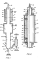
- reactor material (feedstock) and inert gas are (a) fed into the reactor housing 10, wherein the feedstock is heated to a high temperature to cause a desired chemical reaction, (b) passed downward into the insulated housing 12, wherein further decomposition of the reactant may occur, and (c) passed downward through heat exchanger 14, wherein the temperature of the gas and reactants are lowered for subsequent handling.
- reactor material (feedstock) and inert gas are (a) fed into the reactor housing 10, wherein the feedstock is heated to a high temperature to cause a desired chemical reaction, (b) passed downward into the insulated housing 12, wherein further decomposition of the reactant may occur, and (c) passed downward through heat exchanger 14, wherein the temperature of the gas and reactants are lowered for subsequent handling.
- heat exchanger 14 for the present, it should be understood that numerous chemical reactions may be ideally suited for the apparatus herein described.
- the equipment shown in Figure 1 may be used commercially, for example, to generate carbon black from hydrocarbons or to decompose hazardous waste material.
- the reactor section 10 includes a generally cylindrical outer housing 16, a plurality of elongate heating electrodes 18 spaced inwardly of the housing 16, and a generally cylindrical reactor tube 20.
- the selected feed material may be input to the reactor by feed tube 22.
- the electrodes 18 generate radiant heat which is reflected inwardly by the housing 16, causing the reactor tube 20 to be heated to incandescence. Radiant heat from reactor tube 20 in turn radiates energy inwardly to sustain the desired chemical reaction within the reactor tube.
- Inert gas is input without housing 16 through ports 24, and passes through a plurality of apertures in the reactor tube to form an inert gas fluid wall or blanket 26 on the inner surface of the reactor tube.
- the inert gas blanket thus encompasses the generally cylindrical-shaped reaction zone 29 within the reactor tube, with the interface 28 between the inert gas and the reactor zone shown representatively in Figure 1 by dashed lines.
- the post reaction treatment section 12 includes a cylindrical insulated housing 30 which forms a PRTZ chamber 32. Employment of section 12 depends on the desired chemical reaction, and section 12 need not be provided in all cases. Basically, the PRTZ chamber 32 adds "residence time" to the products coming from the reactor section 10, so that further lower temperature decomposition of the gases may occur within the section 12.
- the reactants may be heated to approximately 2430°C to 2650°C within the reactor section 10, and may be maintained at a temperature of between 980°C to 1650°C within the chamber 32.
- various gas ports 33 may be provided for injecting selected gases into the chamber 32.
- the reactants and gas are subsequently input to a water-cooled heat exchanger 14 confined within a cylindrical housing 35.
- Conventional heat exchanger tubes may thus be provided within the chamber 34, with water inlet and outlet ports 36 connecting the heat exchanger tubes to water flow lines. (Alternatively, heat exchanger coils may be provided on the outside of the housing).
- gases and reactants from the chamber 32 may conventionally be lowered by the heat exchanger 14 to approximately 260°C to 650°C for further handling.
- a gas exit port 38 may be provided from the housing 35, although more conventionally a gas exit port 44 may be provided from transition section 40.
- a discharge control 42 may be provided for discharging solid material from the chamber 34, although no appreciable gas flow from control 42 occurs.
- the input gases as well as the reactor-generated gases are transmitted by conduit 46 to cyclone separator 48, which in turn separates the fine particles for discharge through port 50 and discharges gas to a bag filter (not depicted) for a final cleaning operation.
- the fiber material thus produced may oxidize readily.
- the fibers could be collected in a wet scrubber, in a resin or could be sprayed with a protective coating such as oil to prevent oxidization of the final product.
- FIG. 2 a more detailed, although still highly simplified, pictorial view of the reactor section 10 is shown, partially in cross-section. Attached to the ends of cylindrical housing 16 are reduced diameter input cylindrical housing 53 and reduced diameter transition housing 54, each axially aligned with the axis of the housing 16.
- the housing 53 supports a water cooled, adjustable feed tube mechanism 56 which supplies feedstock for the desired chemical reaction.
- a suitable feed tube mechanism is described in detail in U.S. Serial No. 06/647 948, filed on September 5, 1984.
- the transition housing 54 provides both a physical and fluid connection between the reactor section 10 and the post reactor treatment section 12.
- a suitable packing material 58 may be provided between the tubular drip lip member 60 and the inner wall of the housing 53.
- Drip lip 60 may be fabricated from solid graphite, and serves both as an accumulation surfaces for melted solids and vapors which may condense within the housing 53, and a drip ring spaced from the reactor tube 20 so that melted solids and condensed liquids do not flow down onto the reactor tube.
- Electrical power for heating the reactor may be supplied through the power champ connectors 62, which are connected to associated power feedthrough subassemblies 64.
- a plurality of elongate resistance electrodes 18 preferably are uniformly spaced about the interior of the housing 16, and each electrode may be physically supported by and electrically connected at its ends to a suitable electrical connector 66.
- housing 16 reflects radiation inwardly, so that a substantial portion of the radiant energy from electrodes 18 is used to heat the perforated tube 20. More particularly, housing 16 includes a cylindrical shaped radiation shield 68, a cylindrical insulator layer 70, and a cooling jacket 72. The insulator layer 70 and cooling jacket 72 serve to prevent significant temperature increases in the housing wall, and thereby maintain the structural integrity of the housing 16 and minimize housing warpage. A plurality of ports 74 secured to the housing 16 may be provided for attaching suitable sensing equipment to monitor conditions within the reactor.
- FIG. 3 is a pictorial view of a suitable reactor tube 20 according to the present invention.
- Reactor tube 20 may be fabricated from a solid (non-porous) reactor material having a thermal conductivity in the range of 27.7 to 36.3 watt/meter°C at 2200°C, and a material strength of at least 176 kg/sq.cm.
- Solid graphite tubes having an inner diameter of 324 mm and a wall thickness of 6 mm have been successfully employed. At room temperature, solid graphite has a material strength of approximately 351 kg/sq.cm. compared to approximately 35 kg/sq.cm. for porous graphite, so that the structural integrity of the tube is substantially increased by using solid graphite.
- the perforations in the tube constitute only about 7% of the total tube area, so that the thermal conductivity of the perforated graphite tube is still approximately 32.9 watts/ meter°C at 2200°C.
- This increase in thermal conductivity results in a significant increase in the temperature generated within the reaction zone.
- Further reduction in the thickness of the perforated graphite tube may be possible, although a significant advantage of the perforated tube 20 compared to the porous graphite tube is its substantially increased reactor life, and the tube life would probably be reduced if a thinner wall perforated tube were utilized.
- tubes may be periodically removed from the reactor and cleaned (because of a buildup on the outside of the tube discussed subsequently), and much more care would be required when handling thinner wall tubes.
- the tube comprises sections 20A, 20B, and 20C, with each section being identical except for the perforations.
- the perforations 78 through the tube wall are provided along circumferential lines 79A and along vertical columns 79B.
- the holes 78 may be uniformly spaced from each other on the tube sections 20A so that the holes define lattice points of a triangular lattice pattern wrapped around the cylindrical tube.
- holes 78 may be cylindrical holes having a hole axis substantially aligned with the center line 76 of the tube 20.
- the holes may be "gang drilled" in patterns 6 to 12 columns wide, so that the axis of each hole may not be directly in line with the center line 76).
- the holes 78 may be spaced so that a uniform distance is provided between each of the rows 79A, which distance is approximately 1.55 times the uniform distance provided between each of the columns 79B, and the holes 78 are thus uniformly spaced from each other in a triangular lattice pattern.
- Tube section 20C includes cylindrical-shaped holes 80 similar to holes 78, except that holes 80 define lattice points of a rhomboid lattice pattern and are provided along circumferential lines 81A and along spiral columns 81 B.
- the spiral or helical lines 81 B may also be spaced at equal intervals, with a suitable pitch for the helical lines 81 B resulting in hole 80A (spaced five or more rows above hole 80F) being directly vertical over hole 80F.
- Advantages of a triangular, rhomboid and square lattice pattern are discussed subsequently.
- exemplary cylindrical holes 78 and 80 may have a diameter of .76 mm and may be spaced on the tube exterior surface at centerline spacings between holes of 2.54 mm.
- a suitable method for forming a fluid wall will be discussed.
- pressurized inert gas may be injected into the interior of the housing 16. Gases typically have a very low radiation absorption rate, so that the gas would not necessarily be heated to the temperature of the heating elements.
- a pressure differential of between 1.3 to 10.1 gm/sq.cm of water may be created as the gas is passed through the perforations in the tube.
- This pressure differential preferably is sufficient to insure a uniform flow through the perforations in the tube, but is not so high as to cause unnecessary turbulence in the interior of the tube.
- gas may be injected into the tube described above at rates of between 1.1 to 6.8 scmm, and normally below 4.2 scmm. If desired, a low volume of sweep gas less than .57 scmm, may be input into the top of the reactor through control valve 59 (see Figure 2).
- Tube sections may be from less than one foot to several feet in length, and perforations are normally uniformly provided substantially along the length of each perforated section and uniformly about the circumference of each perforated section. Typically, thousands of holes would be provided in a perforated tube section, and thus substantial costs may be incurred when manufacturing perforated tubes according to the present invention.
- a hole diameter of between .51 mm to 5.1 mm should generally be satisfactory, with the uniform hole spacing of between 1.3 mm to 12.7 mm.
- a hole size/hole spacing chart is listed below:
- Tube sections 20B which is unperforated.
- Tube sections can be drilled and section ends either sealingly glued or machined to be fitted to unperforated tube sections, so that inert gas can pass into the interior of the tube only through the perforations provided.
- the inert gas forms a fluid wall between the reaction zone and the interior wall of the tube 20.
- a representative interface between the inert gas and the reaction zone is shown in Figure 1 by the dashed lines 28.
- FIG. 4 there is depicted a cross-section through a portion of a perforated tube provided with holes formed in a rectangular pattern.
- a tube wall having a wall thickness T of 6 mm has an exterior surface 82 and an interior surface 84.
- Circular perforations 90 having a diameter D of .76 mm. are provided through the tube at a hole to hole center line spacing S of 2.54 mm.
- Inert gas flows through the perforations 90 and achieves fairly uniform flow within the perforations because of the D/T ratio.
- An inert gas jet 86 is formed commencing from the end of the opening 90, with the center line of adjacent lower gas jets being designated as 86A-86E.
- the boundary layer 88 of each jet expands outwardly from the center line as the jet progresses from the interior surface 84, and thus each jet may be described as having a substantially conical configuration with the sidewalls of the cones (or the sidewalls of the jets) intersecting at some distance from the interior surface 84. After the jets intersect, a uniform fluid wall is thereafter established, and the jet velocity will continue to decrease as the jet moves further from the interior surface 84.
- the velocity of the gas at any point remains substantially constant, in both magnitude and direction, and there is no mixing of the gases within the jetstream on a macroscopic scale.
- additional mixing or turbulence may occur, which further explains the difficulty in determining whether the jetstream is laminar or tubulent after jetstreams have intersected.
- the hole spacings are believed to be critical to the success of the present invention, and it is believed that the jetstreams maintain sufficient momentum at the point of intersection to form a uniform boundary layer sufficient to repel reactant particles.
- the gas streams should cooperate to repel reactant particles from engaging the inner wall 84 of the tube 20, and it is believed that this repulsion is made possible because each jet maintains a sufficient radially-directed momentum to repel reactant particles at least until the jetstream overlaps with other jetstreams. Once jetstreams having such momentum overlap, an effective continuous fluid wall is created. Thereafter, the radially-directed velocity of the jets will decrease and the inert gas ultimately will flow in an axial direction having no substantial radial component, as shown in Figure 4. It is also believed that the success of the present invention, in part, is due to the fact that the gas jets lose substantially all their radially directed velocity outside of the reaction zone.
- inert gas at or near the interface 28 with the reaction zone is not moving radially with respect to the center line of the tube 20, and therefore does not penetrate the reaction zone interiorly of interface 28 to disturb the fluid flow within the reaction zone.
- reactant gas flow within the reactor zone is substantially laminar, at least after a distance of several feet downstream from the feedstock injection, which enables the axially-moving inert gas to continue to act as an effective fluid wall downstream of the perforations.
- Figure 4 also illustrates perforation 92 having a larger diameter at the exterior wall 82.
- This increased diameter area 94 may be utilized to reduce frictional fluid losses at the entrance to perforation 92, and may also be desirable from a hole manufacturing standpoint if the wall thickness T exceeds 7.6 mm.
- the entrance of perforation 92 may also be cone-shaped or rounded to further reduce frictional entrance losses and/or turbulence.
- Figure 4 also depicts downwardly angled cylindrical perforation 96.
- the axis of perforation 96 if extended, would intersect or pass closely to the center line 76 to tube 20, and in that respect perforation 96 is similar to perforations 90 or 92.
- the axis of cylindrical perforation 96 is projected downwardly (toward the fluid exit of tube 20) so that a jet commencing from perforation 96 is initially imparted with an axially directed velocity in the direction of the ultimate inert gas flow.
- This inclined jet concept has not been adequately tested to determine its effect, although it is believed that a plurality of downwardly injected jets may decrease turbulence within the tube and more readily enable the generation of an axially moving laminar fluid wall.
- this "path” is believed to be desirable especially under abnormal operating conditions, since interior surface tube material in this path remains substantially in its virgin state, while material between such paths experience a slight amount of degregation (microscopic builddown) over an extended period of time.
- An advantage of the spiral configuration of the holes 80 shown in Figure 3 is that the spiral offset allows the "path” inner tube surfaces to overlap, thus effectively obtaining a totally virgin- state inner surface of the tube rather than obtaining a "paths" along the vertical column 79B.
- an advantage of the spiral arrangement of the holes 80 as shown in Figure 3 is that the "path" below hole 80A may extend vertically downward five or more rows past hole 80F, and the elongate path under each of the holes thus overlaps to effectively provide a "virgin state" inner tube surface.
- an effective fluid wall should be formed according to the present invention to keep reactant products from contacting the tube interior wall under normal reactor operating conditions. Because of this "path" effect, the spiral hole arrangement may have advantages to minimize tube deterioration under abnormal operating conditions.
- the drilled tube should be able to structurally withstand compressive forces on the tube when operating at high temperature for extended periods of time. It has been determined that the entrance openings for the perforations may tend to increase with a conical configuration as the tube life increases. This conical increase or erosion of the entrance areas of the perforations is generally symmetrical with respect to the center line of each perforation, and after a relatively long period of time, the erosion of the outer wall adjacent the opening of each hole effectively decreases the compressive strength of the tube, the tube strength being effectively determined by the strength of the "columns" of core material between the columns of holes.
- a square or rectangular lattice pattern is preferably over the arrangement of the holes 80 to minimize the likelihood of tube structural failure over a long operating period.
- a triangular hole pattern offers increased "cleaned path" surfaces compared to a square hole pattern, while still retaining narrower vertical outer wall columns between holes.
- a hexagonal or outer hole pattern may also be used, depending on the desired tradeoff between reactor tube strength and the efficiency of the hole pattern in forming and maintaining a fluid wall.
- a perforated section of the tube may be essential in the vicinity where the feedstock is input into the reactor.
- individual particles of reactant material and reaction-created gas molecules may have a substantial radial as well as axial velocity, due to the intensity of the chemical reactions and the creation of new reaction gases.
- This supposedly turbulent condition results in reaction particles in the range of up to approximately 0.5 mm being thrust with a radially-directed velocity toward the reactor tube, and these particles are repelled from contacting the inner surface of the reactor tube by the opposing radially-directed momentum of the overlapping jets.
- Figure 5 illustrates a simplified cross-sectional view of a reactor chamber including a modified reactor tube.
- the reactor includes the cylindrical housing 16 for the heating elements 18, as previously discussed.
- the feed tube 22 terminates within the upper housing 53, and the lower housing 54 provides a transition to the downstream equipment.
- the reactor tube shown in Figure 5 comprises three separate reactor tube sections: a perforated tube section 102 extending from the top of the tube until about the middle of the housing 16, a solid and unperforated tube section 104 extending from tube 102 to position adjacent the lower end of the large cylindrical housing 16, and a perforated tube section 106 extending from the tube 104 to the lower end of the reactor tube.
- a perforated tube section 102 extending from the top of the tube until about the middle of the housing 16
- a solid and unperforated tube section 104 extending from tube 102 to position adjacent the lower end of the large cylindrical housing 16
- a perforated tube section 106 extending from the tube 104 to the lower end of the reactor tube.
- Each of these tube sections is axially aligned and may be sealingly joined by conventional means.
- Inert gas may be injected through one or more of the ports 110 for passing inert gas through the perforations in section 102 to form the desired fluid wall comprising a plurality of radially projecting jets in the vicinity of the feedstock input.
- the reactor material and gases within the reaction zone should be moving substantially axially with respect to the axis of the tube.
- An unperforated tube section 104 of several feet or more in length may thus be provided, with the fluid wall being maintained by the laminar axially moving inert gas flow, as described above.
- turbulence within the reactor tube may be increasing, and the fluid wall may begin to break-down. Accordingly, another perforated section of reactor tube 106 is provided to insure that the reactant particles do not come into engagement with the lower end of the reaction tube.
- inert gas may be input into the reactor only in the vicinity of the perforated tube sections.
- inert gas may be input into a chamber in fluid communication with the perforations in a perforated section of the tube, but sealed from the adjacent unperforated sections of the tube.
- An unperforated section of the tube is preferably provided in a hot zone, since this is the zone which would otherwise most likely experience tube failure due to the extended temperatures and corrosion of the outer wall.
- inert gas may thus be injected through ports 110 in housings 53 and 54, while port 110 in housing 16 is sealed.
- the closing of port 110 in housing 16 should reduce the buildup on the outside of perforated tube sections 102 and 106, since the injected gas need not pass by the elements 18 before entering the perforations in the tube.
- FIG. 6 another reactor is shown, with a reactor tube comprising alternating perforated and unperforated sections 114, 116, 118, 120, 122, and 123.
- Each of the perforated sections is sealed outwardly from the unperforated sections by graphite packing rings 125 and/or other horizontal barrier layers.
- the perforated section 114 is sealed from the chamber outside of the unperforated section 116 containing the heating elements 18.
- perforated section 118 is sealed from adjacent unperforated sections by horizontal barriers 128 and 130.
- Each of the perforated sections shown in Figure 6 is provided with its own inert gas input 110.
- inert gas entering the reactor tube need not be in fluid communication with the hot portion outside the unperforated section of the tube adjacent the heating elements 18.
- the fluid dynamics of the inert gas will largely depend on the gas temperature.
- the inert gas may not be as hot as the gas passing through the tube of the embodiment shown in Figure 5.
- the inert gas provided to the perforated sections of the tube shown in Figure 6 may be preheated by conventional means.
- Figure 6 illustrates that a short perforated tube section 118 may be provided between an otherwise elongate hot zone. Laminar flow of inert gas within the unperforated section 116 may begin to break down, and perforated tube section 118 is provided to reestablish a strong fluid wall and again commence uniform laminar flow of the inert gas adjacent the interior of the unperforated section 120.
- Figure 6 also illustrates that unperforated sections of the reactor tube may be provided in the area generally adjacent the heating elements, while perforated tube sections are provided in the relatively cool reactor zones. Finally, restricting the flow of inert gas from the heating elements 18 as shown in Figure 6 may extend the life of the heating elements, although additional life from the elements 18 may also be obtained by using another inert gas, such as argon.
- perforated tube sections wherein the hole size, hole spacing, and hole orientation vary depending upon the intended placement of the tube section relative to the feedstock input location and the heating and cooling zones.
- perforations in sections 118 and 122 may be angled downwardly, as previously described, to achieve a uniform downstream laminar fluid wall without generating a strictly radially-directed pattern of jets, since fluid gas and reactants entering these zones should be moving substantially in the axial direction.
- the perforated tube allows for a much stronger fluid wall to repel reactants than was obtained using the porous tube.
- the perforated tube of the present invention requires much less inert gas than the porous tube, thus both reducing reactor operating costs and allowing the downsizing of gas purification equipment.
- the increased thermal conductivity of the reactor tube compared to porous reactor tube results in a higher reaction temperature and therefore increases the reactor efficiency.
- the perforated reactor tube of the present invention has a relatively high resistance to chemical attack due to its non-porous nature, and is much stronger than a porous reactor tube, as previously explained. It is therefore believed that the perforated tube may typically have a reactor life of at least fifty times the life of a porous tube.
- the present invention thus makes feasible the commercial operation of a reactor utilizing a perforated tube diameter of from .36 to 1.52 m.
- a reactor may, for example, be used to commercially produce carbon black, to gasify coal by pyrolysis, to decompose hazardous waste materials, to thermally crack petroleum products, or to reduce oxides of inorganic compounds in the presence of hydrogen.
- Numerous other possible uses for the high temperature fluid wall reactor are disclosed in the US-A-4 044117 which are incorporated herein by reference.
- .70 mm diameter holes are provided in a drilled section of a 324 mm ID, 354 mm OD core, at 2.54 mm hole spacings.
- a 13 foot (4.0 m) long cylindrical core has at least .91 m, and preferably at least 1.2 m, of total drilled core sections, with approximately 1.8 m of the core heated directly and an additional .6 to 1.2 m heated by radiation spillage.
- the holes are preferably drilled perpendicular to the core axis, rather than at an inclined angle.
- Two .61 m sections of drilled core are separated by a 1.82 m solid core section in the hot zone.
- the drilled core sections may be isolated from the electrodes in the manner as shown in Figure 6.
- a PRTZ section approximately 1.5 m diameter and 6.1 m long may be utilized.
- This post reactor treatment section need not necessarily be insulated.
- the PRTZ section may be cooled on the outside, irrespective of whether insulating material (e.g., insulating brick) is or is not utilized.
- the PRTZ section may be cooled by a simple water-cooled tank internal to the shell, as previously described, and again insulating material may or may not be utilized depending on the desired reaction and preferred temperature gradient within the PRTZ section.
- the above-described reactor core may be used in the destruction of soil contaminated with harzardous waste.
- Between .09 to .33 scmm and preferably between .13 to .27 scmm of nitrogen per .093 square meters of drilled core area is utilized to form an effective blanket.
- Injection of inert gas rates greater than that necessary to form a blanket may cause increased turbulence in the core and therefore decrease core life and reactor efficiency.
- nitrogen is preferably heated to at least 427°C.
- a high purity inert gas is utilized to decrease core degradation; nitrogen with less than 1 part per million oxygen and water may be produced by conventional equipment, or may be commercially purchased. Excess hydrogen in the nitrogen may decrease core life, especially if the drilled core sections are positioned in the hot section of the reactor.
- a relatively "tight" soil column in the reactor may be obtained inputting as much as 640 kg of soil per minute into the reactor (freefalling), and injecting approximately 5.7 scmh of nitrogen in the feed tube area to stabilize soil flow.
- the injection of a low-volume nitrogen gas with the feed material results in the velocity of the gas about the feed material approximating the feed material velocity, thereby reducing aspirating gases and decreasing turbulences. Injection of too much gas in the feed tube area may tend to blast soil particles toward the reactor wall, and may therefore be dangerous to core life and/or decrease the effectiveness of the desired reaction within the core.
- the nitrogen may be preheated to 800°F or more, placement of the drilled core sections in the relatively "cool" zone of the reactor may substantially decrease the ability to form an effective blanket. It should therefore be understood that, depending on the nature of the chemical reaction intended, it may nevertheless be beneficial to place the drilled core sections in the "hot" zones of the reactor adjacent the cool zones, rather than in the cool zones themselves. Although this modification may increase core degradation, the benefit of a more effective blanket of inert gas may be obtained.
- the maximum practical length of solid core section may be approximately 1.8 m while still maintaining an effective blanket of inert gas, and accordingly, placement of the drilled core sections toward but not in the cool zones may decrease the need for any drilled core sections toward the middle of the hot zone.
- inductive heating rather than resistance heating.
- the electrodes described herein could be replaced with inductive heaters, which would similarly radiate energy to the reactor tube, which in turn would radiate the reaction zone to sustain the desired chemical reaction.
- Large inductive heaters are commercially available, so that the commercial scale-up of such a reactor is feasible.
- the use of inductive heaters compared to resistance heaters may also increase the heat transfer efficiency to the feedstock, and may eliminate some difficulties associated with the use of resistance electrodes operating within high temperatures environments.
- the reactor tube of the present invention is thus particularly useful for a high-temperature fluid wall reactor wherein the reaction zone spaced within the interior of the tube is substantially heated by radiant energy. In many instances, this radiant energy is absorbed by the reactant itself, which raises the temperature within the reaction zone so that reaction gases within the reaction zone (having a relatively low radiation absorption coefficient) are heated by both convention and radiation.
- the US-A-4 044 117 teaches that if the reactant itself does not exhibit a high radiation absorption rate, a "target material" may be added to the reaction zone to raise the temperature in the reaction zone.
- the tube of the present invention is well suited for radiation coupling type reactors, wherein radiation heaters radiate a tube which in turn radiates a radially inward reaction zone. Alternatively, a tube material having a very low radiation absorption coefficient may be used, so that radiation from heaters passes through the tube, and the reaction zone is thus radiantly heated directly by the heaters exterior to the tube.
- Suitable core materials are Stackpole 2020 or Stackpole 2191, each a fine grain graphite material commercially available from Stackpole Corporation in St. Marys, Pennsylvania.
- This core material may be purified by a vacuum of gasing, or "F" purifying processes, both standard techniques in graphite technology, which reduce impurities in the material and increase core life. Vacuum out gasing may typically reduce iron content in the drilled core from 600 to 50 parts per million, and similarly reduce calcium from 200 to 20 parts per million and silicon from 300 to 30 parts per million.
- Another carbon/carbon composition material is available from Carbon Carbon Advance Technologies, Inc. in Fort Worth, Texas. This material, made from mats of graphite cloth impregnated with carbon resin which is then graphitized is stronger than Stackpole 2020, and should therefore experience less degradation and have a longer life.
- Minimizing such hole plugging may be obtained by isolating the drilled holes from gases in fluid communication with the electrodes (although an effective blanket must still be maintained), by using higher quality electrodes with less impurities to decrease vaporization, or by increasing electrode surface areas to decrease heat flux through the electrode cross-section. Electrodes fabricated from and purified by the techniques described above with respect to cores may therefore minimize hole plugging.
- the reactor tube may be fabricated from graphite, as described above, although many other refractory materials may be used. Examples of other suitable reactor tube materials include carbon, silicon carbide, boron nitride, and silicon nitride.
- the reactor tube material may in turn determine the preferred technique for perforating the tube. Conventional rotary drilling has been utilized for graphite tubes, although both ultrasonic drilling and laser drilling have also been successfully employed. If laser drilling is employed, perforations may be frusto-conically shaped rather than cylindrical, but this should not detract from the ability of the perforated tube to generate a protective fluid wall. Various gases other than nitrogen and argon may be used.
- the selected inert fluid should be substantially transparent to radiation, and should also be substantially inert with respect to the reactor tube material at various temperatures. Other suitable inert gases include hydrogen, helium, and xenon.
- feedstock material for forming the fiber material of the present invention several formulations have also been successful. These include differing types of inorganic material such as sand, ground glass, soil, and zircon as a source of silicon, and differing types of oil and carbon blacks, halogenated organics, and propane as a source of carbon to enhance the reaction.
Landscapes
- Chemical & Material Sciences (AREA)
- Organic Chemistry (AREA)
- Chemical Kinetics & Catalysis (AREA)
- General Chemical & Material Sciences (AREA)
- Engineering & Computer Science (AREA)
- Crystallography & Structural Chemistry (AREA)
- Materials Engineering (AREA)
- Metallurgy (AREA)
- Crystals, And After-Treatments Of Crystals (AREA)
- Physical Or Chemical Processes And Apparatus (AREA)
- Inorganic Fibers (AREA)
Claims (22)
Priority Applications (1)
| Application Number | Priority Date | Filing Date | Title |
|---|---|---|---|
| AT85110886T ATE59152T1 (de) | 1984-09-05 | 1985-08-29 | Fluid-wand-reaktor. |
Applications Claiming Priority (8)
| Application Number | Priority Date | Filing Date | Title |
|---|---|---|---|
| US64840384A | 1984-09-05 | 1984-09-05 | |
| US647958 | 1984-09-05 | ||
| US06/647,958 US4643890A (en) | 1984-09-05 | 1984-09-05 | Perforated reactor tube for a fluid wall reactor and method of forming a fluid wall |
| US648403 | 1984-09-05 | ||
| US76660885A | 1985-08-16 | 1985-08-16 | |
| US06/766,844 US4671944A (en) | 1984-09-05 | 1985-08-16 | Perforated reactor tube and method for forming a fluid wall in a reactor |
| US766844 | 1985-08-16 | ||
| US766608 | 1991-09-26 |
Publications (3)
| Publication Number | Publication Date |
|---|---|
| EP0176770A2 EP0176770A2 (de) | 1986-04-09 |
| EP0176770A3 EP0176770A3 (en) | 1988-07-27 |
| EP0176770B1 true EP0176770B1 (de) | 1990-12-19 |
Family
ID=27505260
Family Applications (1)
| Application Number | Title | Priority Date | Filing Date |
|---|---|---|---|
| EP85110886A Expired EP0176770B1 (de) | 1984-09-05 | 1985-08-29 | Fluid-Wand-Reaktor |
Country Status (9)
| Country | Link |
|---|---|
| EP (1) | EP0176770B1 (de) |
| AU (1) | AU570167B2 (de) |
| CA (1) | CA1254356A (de) |
| DE (1) | DE3580959D1 (de) |
| DK (1) | DK402985A (de) |
| ES (1) | ES8708152A1 (de) |
| FI (1) | FI853375L (de) |
| IL (1) | IL76290A (de) |
| NZ (1) | NZ213363A (de) |
Families Citing this family (2)
| Publication number | Priority date | Publication date | Assignee | Title |
|---|---|---|---|---|
| WO2021068084A1 (en) * | 2019-10-09 | 2021-04-15 | Tekna Plasma Systems Inc. | Nanosize powder advanced materials, method of manufacturing and of using same |
| CN116520712B (zh) * | 2023-07-03 | 2023-08-22 | 贵阳职业技术学院 | 一种反应容器入料量自适应调控方法、系统、终端及介质 |
Family Cites Families (4)
| Publication number | Priority date | Publication date | Assignee | Title |
|---|---|---|---|---|
| US2823979A (en) * | 1954-05-28 | 1958-02-18 | Goodrich Co B F | Method of making pigment |
| US3203763A (en) * | 1963-01-17 | 1965-08-31 | Du Pont | Production of metal oxides through oxidation of metal halides |
| US4012201A (en) * | 1973-03-22 | 1977-03-15 | Tioxide Group Limited | Reactor |
| US4199545A (en) * | 1975-08-20 | 1980-04-22 | Thagard Technology Company | Fluid-wall reactor for high temperature chemical reaction processes |
-
1985
- 1985-08-26 CA CA000489419A patent/CA1254356A/en not_active Expired
- 1985-08-29 DE DE8585110886T patent/DE3580959D1/de not_active Expired - Fee Related
- 1985-08-29 EP EP85110886A patent/EP0176770B1/de not_active Expired
- 1985-09-03 FI FI853375A patent/FI853375L/fi not_active IP Right Cessation
- 1985-09-04 NZ NZ213363A patent/NZ213363A/en unknown
- 1985-09-04 IL IL76290A patent/IL76290A/xx not_active IP Right Cessation
- 1985-09-04 AU AU47057/85A patent/AU570167B2/en not_active Ceased
- 1985-09-04 DK DK402985A patent/DK402985A/da not_active Application Discontinuation
-
1986
- 1986-09-01 ES ES557080A patent/ES8708152A1/es not_active Expired
Also Published As
| Publication number | Publication date |
|---|---|
| FI853375A7 (fi) | 1986-03-06 |
| DE3580959D1 (en) | 1991-01-31 |
| AU570167B2 (en) | 1988-03-03 |
| IL76290A (en) | 1988-06-30 |
| IL76290A0 (en) | 1986-01-31 |
| EP0176770A2 (de) | 1986-04-09 |
| AU4705785A (en) | 1986-03-13 |
| EP0176770A3 (en) | 1988-07-27 |
| DK402985D0 (da) | 1985-09-04 |
| NZ213363A (en) | 1988-03-30 |
| FI853375A0 (fi) | 1985-09-03 |
| FI853375L (fi) | 1986-03-06 |
| ES557080A0 (es) | 1987-09-16 |
| ES8708152A1 (es) | 1987-09-16 |
| CA1254356A (en) | 1989-05-23 |
| DK402985A (da) | 1986-03-06 |
Similar Documents
| Publication | Publication Date | Title |
|---|---|---|
| US4643890A (en) | Perforated reactor tube for a fluid wall reactor and method of forming a fluid wall | |
| EP1448818B1 (de) | Verbrennungsapparatur und verfahren zur herstellung von carbonnanomaterial | |
| KR101678661B1 (ko) | 유동층 반응기 | |
| JPH039047B2 (de) | ||
| US4208373A (en) | Reactor-tube assembly for fluid-wall reactors for high temperature chemical reaction processes | |
| US4671944A (en) | Perforated reactor tube and method for forming a fluid wall in a reactor | |
| US4335080A (en) | Apparatus for producing selective particle sized oxide | |
| US10690341B2 (en) | Systems and methods for improved waste gas abatement | |
| JP4597863B2 (ja) | シリコン製造装置 | |
| JP2006527157A (ja) | 炭化珪素の結晶を成長させるシステム | |
| US20070275335A1 (en) | Furnace for heating particles | |
| EP0176770B1 (de) | Fluid-Wand-Reaktor | |
| KR102241298B1 (ko) | 고주파 유도 가열을 이용한 수소 생산용 개질 반응 장치 | |
| TWI579419B (zh) | 製備顆粒狀多晶矽的反應器和方法 | |
| EP1642866A1 (de) | Verfahren zur herstellung von fulleren | |
| US4275493A (en) | Method for making a fabric reactor tube | |
| JPH0741314A (ja) | 炭化物製造方法及びその装置 | |
| JPS5811494B2 (ja) | 金属溶湯の脱ガス処理装置 | |
| US4284879A (en) | Methods of containing fluids deleterious to the container | |
| JPH08268926A (ja) | 飽和または不飽和脂肪族炭化水素のアセチレン系炭化水素への熱転換方法 | |
| EP1798198B1 (de) | Vorrichtung zur herstellung von silicium | |
| KR890002965B1 (ko) | 고순도 반도체 규소박판을 이용한 고순도 반도체 재료인 규소의 제조방법 및 장치 | |
| US3124425A (en) | Richelsen | |
| NZ231496A (en) | Cracking heavy hydrocarbons using light alkane free radicals produced in a plasma and a fluidised catalytic bed | |
| US2657247A (en) | High-temperature electric furnace and process of operation |
Legal Events
| Date | Code | Title | Description |
|---|---|---|---|
| PUAI | Public reference made under article 153(3) epc to a published international application that has entered the european phase |
Free format text: ORIGINAL CODE: 0009012 |
|
| AK | Designated contracting states |
Kind code of ref document: A2 Designated state(s): AT BE CH DE FR GB IT LI LU NL SE |
|
| RHK1 | Main classification (correction) |
Ipc: B01J 12/00 |
|
| PUAL | Search report despatched |
Free format text: ORIGINAL CODE: 0009013 |
|
| AK | Designated contracting states |
Kind code of ref document: A3 Designated state(s): AT BE CH DE FR GB IT LI LU NL SE |
|
| 17P | Request for examination filed |
Effective date: 19890117 |
|
| 17Q | First examination report despatched |
Effective date: 19890731 |
|
| GRAA | (expected) grant |
Free format text: ORIGINAL CODE: 0009210 |
|
| DX | Miscellaneous (deleted) | ||
| AK | Designated contracting states |
Kind code of ref document: B1 Designated state(s): AT BE CH DE FR GB IT LI LU NL SE |
|
| PG25 | Lapsed in a contracting state [announced via postgrant information from national office to epo] |
Ref country code: SE Free format text: THE PATENT HAS BEEN ANNULLED BY A DECISION OF A NATIONAL AUTHORITY Effective date: 19901219 Ref country code: NL Effective date: 19901219 Ref country code: IT Free format text: LAPSE BECAUSE OF FAILURE TO SUBMIT A TRANSLATION OF THE DESCRIPTION OR TO PAY THE FEE WITHIN THE PRESCRIBED TIME-LIMIT;WARNING: LAPSES OF ITALIAN PATENTS WITH EFFECTIVE DATE BEFORE 2007 MAY HAVE OCCURRED AT ANY TIME BEFORE 2007. THE CORRECT EFFECTIVE DATE MAY BE DIFFERENT FROM THE ONE RECORDED. Effective date: 19901219 Ref country code: FR Effective date: 19901219 Ref country code: BE Effective date: 19901219 |
|
| REF | Corresponds to: |
Ref document number: 59152 Country of ref document: AT Date of ref document: 19910115 Kind code of ref document: T |
|
| REF | Corresponds to: |
Ref document number: 3580959 Country of ref document: DE Date of ref document: 19910131 |
|
| EN | Fr: translation not filed | ||
| NLV1 | Nl: lapsed or annulled due to failure to fulfill the requirements of art. 29p and 29m of the patents act | ||
| PG25 | Lapsed in a contracting state [announced via postgrant information from national office to epo] |
Ref country code: GB Effective date: 19910829 Ref country code: AT Effective date: 19910829 |
|
| PG25 | Lapsed in a contracting state [announced via postgrant information from national office to epo] |
Ref country code: LU Free format text: LAPSE BECAUSE OF NON-PAYMENT OF DUE FEES Effective date: 19910831 Ref country code: LI Effective date: 19910831 Ref country code: CH Effective date: 19910831 |
|
| PLBE | No opposition filed within time limit |
Free format text: ORIGINAL CODE: 0009261 |
|
| STAA | Information on the status of an ep patent application or granted ep patent |
Free format text: STATUS: NO OPPOSITION FILED WITHIN TIME LIMIT |
|
| 26N | No opposition filed | ||
| GBPC | Gb: european patent ceased through non-payment of renewal fee | ||
| REG | Reference to a national code |
Ref country code: CH Ref legal event code: PL |
|
| PG25 | Lapsed in a contracting state [announced via postgrant information from national office to epo] |
Ref country code: DE Effective date: 19920501 |