EP0176335B1 - Pipe handling apparatus - Google Patents
Pipe handling apparatus Download PDFInfo
- Publication number
- EP0176335B1 EP0176335B1 EP85306752A EP85306752A EP0176335B1 EP 0176335 B1 EP0176335 B1 EP 0176335B1 EP 85306752 A EP85306752 A EP 85306752A EP 85306752 A EP85306752 A EP 85306752A EP 0176335 B1 EP0176335 B1 EP 0176335B1
- Authority
- EP
- European Patent Office
- Prior art keywords
- platform
- conveyor
- lift
- chassis
- pipe
- Prior art date
- Legal status (The legal status is an assumption and is not a legal conclusion. Google has not performed a legal analysis and makes no representation as to the accuracy of the status listed.)
- Expired
Links
- 230000033001 locomotion Effects 0.000 claims abstract description 32
- 238000000034 method Methods 0.000 claims description 6
- 238000005096 rolling process Methods 0.000 claims description 3
- 238000005553 drilling Methods 0.000 abstract description 8
- 239000003129 oil well Substances 0.000 abstract 1
- 239000011121 hardwood Substances 0.000 description 5
- 230000007246 mechanism Effects 0.000 description 4
- 238000010276 construction Methods 0.000 description 3
- 230000009471 action Effects 0.000 description 2
- 230000000712 assembly Effects 0.000 description 2
- 238000000429 assembly Methods 0.000 description 2
- 230000001965 increasing effect Effects 0.000 description 2
- 230000008569 process Effects 0.000 description 2
- 230000002441 reversible effect Effects 0.000 description 2
- 229910000831 Steel Inorganic materials 0.000 description 1
- 230000003466 anti-cipated effect Effects 0.000 description 1
- 238000013459 approach Methods 0.000 description 1
- 230000003028 elevating effect Effects 0.000 description 1
- 239000000463 material Substances 0.000 description 1
- 239000010959 steel Substances 0.000 description 1
- 230000032258 transport Effects 0.000 description 1
Images


Classifications
-
- B—PERFORMING OPERATIONS; TRANSPORTING
- B60—VEHICLES IN GENERAL
- B60P—VEHICLES ADAPTED FOR LOAD TRANSPORTATION OR TO TRANSPORT, TO CARRY, OR TO COMPRISE SPECIAL LOADS OR OBJECTS
- B60P1/00—Vehicles predominantly for transporting loads and modified to facilitate loading, consolidating the load, or unloading
- B60P1/02—Vehicles predominantly for transporting loads and modified to facilitate loading, consolidating the load, or unloading with parallel up-and-down movement of load supporting or containing element
- B60P1/025—Vehicles predominantly for transporting loads and modified to facilitate loading, consolidating the load, or unloading with parallel up-and-down movement of load supporting or containing element with a loading platform inside the wheels of a same axle and being lowerable below the axle
-
- B—PERFORMING OPERATIONS; TRANSPORTING
- B65—CONVEYING; PACKING; STORING; HANDLING THIN OR FILAMENTARY MATERIAL
- B65G—TRANSPORT OR STORAGE DEVICES, e.g. CONVEYORS FOR LOADING OR TIPPING, SHOP CONVEYOR SYSTEMS OR PNEUMATIC TUBE CONVEYORS
- B65G41/00—Supporting frames or bases for conveyors as a whole, e.g. transportable conveyor frames
- B65G41/001—Supporting frames or bases for conveyors as a whole, e.g. transportable conveyor frames with the conveyor adjustably mounted on the supporting frame or base
- B65G41/005—Supporting frames or bases for conveyors as a whole, e.g. transportable conveyor frames with the conveyor adjustably mounted on the supporting frame or base mounted for both pivotal and linear movement
-
- B—PERFORMING OPERATIONS; TRANSPORTING
- B66—HOISTING; LIFTING; HAULING
- B66F—HOISTING, LIFTING, HAULING OR PUSHING, NOT OTHERWISE PROVIDED FOR, e.g. DEVICES WHICH APPLY A LIFTING OR PUSHING FORCE DIRECTLY TO THE SURFACE OF A LOAD
- B66F7/00—Lifting frames, e.g. for lifting vehicles; Platform lifts
- B66F7/06—Lifting frames, e.g. for lifting vehicles; Platform lifts with platforms supported by levers for vertical movement
- B66F7/0625—Lifting frames, e.g. for lifting vehicles; Platform lifts with platforms supported by levers for vertical movement with wheels for moving around the floor
-
- B—PERFORMING OPERATIONS; TRANSPORTING
- B66—HOISTING; LIFTING; HAULING
- B66F—HOISTING, LIFTING, HAULING OR PUSHING, NOT OTHERWISE PROVIDED FOR, e.g. DEVICES WHICH APPLY A LIFTING OR PUSHING FORCE DIRECTLY TO THE SURFACE OF A LOAD
- B66F7/00—Lifting frames, e.g. for lifting vehicles; Platform lifts
- B66F7/06—Lifting frames, e.g. for lifting vehicles; Platform lifts with platforms supported by levers for vertical movement
- B66F7/065—Scissor linkages, i.e. X-configuration
- B66F7/0666—Multiple scissor linkages vertically arranged
- B66F7/0675—Auxiliary scissors, e.g. above main scissors
-
- B—PERFORMING OPERATIONS; TRANSPORTING
- B66—HOISTING; LIFTING; HAULING
- B66F—HOISTING, LIFTING, HAULING OR PUSHING, NOT OTHERWISE PROVIDED FOR, e.g. DEVICES WHICH APPLY A LIFTING OR PUSHING FORCE DIRECTLY TO THE SURFACE OF A LOAD
- B66F7/00—Lifting frames, e.g. for lifting vehicles; Platform lifts
- B66F7/06—Lifting frames, e.g. for lifting vehicles; Platform lifts with platforms supported by levers for vertical movement
- B66F7/08—Lifting frames, e.g. for lifting vehicles; Platform lifts with platforms supported by levers for vertical movement hydraulically or pneumatically operated
-
- E—FIXED CONSTRUCTIONS
- E21—EARTH OR ROCK DRILLING; MINING
- E21B—EARTH OR ROCK DRILLING; OBTAINING OIL, GAS, WATER, SOLUBLE OR MELTABLE MATERIALS OR A SLURRY OF MINERALS FROM WELLS
- E21B19/00—Handling rods, casings, tubes or the like outside the borehole, e.g. in the derrick; Apparatus for feeding the rods or cables
- E21B19/14—Racks, ramps, troughs or bins, for holding the lengths of rod singly or connected; Handling between storage place and borehole
-
- E—FIXED CONSTRUCTIONS
- E21—EARTH OR ROCK DRILLING; MINING
- E21B—EARTH OR ROCK DRILLING; OBTAINING OIL, GAS, WATER, SOLUBLE OR MELTABLE MATERIALS OR A SLURRY OF MINERALS FROM WELLS
- E21B19/00—Handling rods, casings, tubes or the like outside the borehole, e.g. in the derrick; Apparatus for feeding the rods or cables
- E21B19/14—Racks, ramps, troughs or bins, for holding the lengths of rod singly or connected; Handling between storage place and borehole
- E21B19/15—Racking of rods in horizontal position; Handling between horizontal and vertical position
- E21B19/155—Handling between horizontal and vertical position
-
- Y—GENERAL TAGGING OF NEW TECHNOLOGICAL DEVELOPMENTS; GENERAL TAGGING OF CROSS-SECTIONAL TECHNOLOGIES SPANNING OVER SEVERAL SECTIONS OF THE IPC; TECHNICAL SUBJECTS COVERED BY FORMER USPC CROSS-REFERENCE ART COLLECTIONS [XRACs] AND DIGESTS
- Y10—TECHNICAL SUBJECTS COVERED BY FORMER USPC
- Y10S—TECHNICAL SUBJECTS COVERED BY FORMER USPC CROSS-REFERENCE ART COLLECTIONS [XRACs] AND DIGESTS
- Y10S414/00—Material or article handling
- Y10S414/13—Handlers utilizing parallel links
Definitions
- This invention relates to pipe handling equipment, and, more particularly but not exclusively, to apparatus for transferring pipes to and from an oil drilling rig.
- U.S. Patent 3,103,291 shows a vehicle useful for loading and unloading airplanes
- U.S. Patent 3,446,379 shows a scissors-type high lift elevating mechanism
- U.S. Patent 4,162,873 discloses an extensible boom lift which includes a table mounted on a scissors-type lifting device and supporting a beam which is rotatable about a vertical axis. An extensible boom is supported by the rotatable beam.
- U.S. Patent 2,617,547 discloses a pipe loading device having lifting arms attached to a chassis and adapted to raise lengths of pipe from the ground to a pair of transversely inclined pipe rests.
- the pipe rests are supported by a scissors-type lifting platform for vertically raising the pipes to a higher level.
- the device of the 2,617,547 patent is disadvantageous because the pipe on the platform cannot be transferred under power along a longitudinal axis, and also because the pipe remains horizontal during lifting operations, thereby making it difficult to grab by a pipe elevator.
- U.S. Patent 2,676,715 shows a self-loading truck having loading arms for raising pipe from the ground to a selected height above the bed of the truck.
- the truck does not include means for unloading the pipe from a drilling rig.
- U.S. Patent 3,785,506 shows a drill pipe handling apparatus for controlling the descent of a pipe from a derrick floor to a lower pipe support, and from the pipe support to a pipe rack therebelow.
- the device of the 3,785,506 patent is not capable of raising pipe from the ground to a derrick floor.
- U.S. Patent 3,810,553 illustrates a pipe handling device which is capable of lifting a pipe from the ground onto a pair of connected dollies.
- the dollies are reciprocable to move the pipe longitudinally onto and up an inclined chute to the rig platform.
- the device is also capable of the reverse operation of transporting a pipe from the rig to the ground.
- U.S. Patent 4,054,210 shows a pipe carrier which is movably mounted on an elevated first cable suspended between the ground and derrick.
- a disadvantage of the devices of the 3,785,506; 3,810,553; and 4,054,210 patents is that they cannot be readily moved to other stacks of pipes or derricks.
- U.S. Patent 4,236,861 shows a pipe handler with a scissors lift for supporting a platform and pipe support racks.
- a pivotable lifting mechanism transports the pipes from the ground to the platform rails.
- a selected pipe is positioned over a pipe lifting device which raises it vertically above the rails to a desired height.
- the handler does not include any mechanism for assisting the horizontal transfer of a pipe to another structure.
- US-A-3 916 500 discloses an apparatus for transferring pipe between a supply thereof and a location vertically and horizontally distant from the supply comprising;
- a need exists for a transportable pipe handling device which is capable of efficiently manipulating heavy pipe through large vertical and horizontal distances between a stack thereof and a rig platform and that provides for a combination of translational movement of the conveyor means along and rotational movement of the conveyor means relative to a chassis of the device.
- the present invention provides apparatus for transferring pipe between a supply thereof and a location vertically and horizontally distant from the supply comprising;
- the conveyor and platform are fully collapsible so as to nest into the chassis, and the conveyor may have a longitudinally extending trough adapted to receive the pipe.
- two or more arms may be pivotally mounted to the chassis for lifting the pipe to the top level of the nested platform.
- the pipe can than roll across the top level of the platform onto a conveyor belt, which forms the bottom surface of the trough.
- the conveyor lifting device may be designed so that as it is extended under hydraulic power to raise the conveyor vertically, it also imparts a horizontal movement to the conveyor.
- the conveyor lift means may be mounted to the platform which is vertically raisable in conventional fashion by a scissor-type lift.
- the platform scissors lift is then supported by the carriage means which reciprocates along the chassis, thus providing additional horizontal movement to the pipe for reaching the required position on the rig platform.
- the carriage means may be designed with a base which slides along and is supported by tracks in the chassis and with a table which is swivellably supported by the base for rotation about a vertical axis.
- the chassis tracks for the carriage base are on two levels. The lower level extends for the majority of the length of the chassis. When the carriage is in the lower level, the table cannot swivel.
- Ramped tracks join the upper and lower track levels, so that the carriage may be rolled between the upper and lower levels.
- the carriage table When in the upper level tracks, the carriage table may swivel on each side of the chassis longitudinal axis.
- the versatility is greatly increased because it is capable of handling pipes which are stacked in any orientation relative to the drilling rig.
- the platform which supports the conveyor and conveyor lift device, may also be horizontally slidable relative to the chassis, carriage, and platform lift.
- the platform includes a longitudinally extensible brace which is insertable inside the platform.
- the outer end of the extensible brace is then provided with vertically adjustable legs capable of contacting the ground regardless of the height of the platform.
- the brace and legs support one end of the platform when the platform is moved horizontally out of contact with one of the platform lift support members, so that the platform is supported only by a second platform lift support member and the extended brace.
- the conveyor may also be designed to translate relative to the conveyor lift device.
- the carriage table may be swivelled prior to the platform and/or conveyor being moved horizontally relative to the carriage. Consequently, maximum versatility for accurately manipulating the pipe to a wide variety of rig platform locations is achieved, thereby increasing the drilling efficiency.
- the conveyor belt may be built in at least two sections with longitudinal spaces between the sections.
- a tapered spade protrudes through the spaces so as to eject the pipe from the conveyor and deflect it to a selected side of the chassis for returning to the pipe stack.
- a pipe handling apparatus 1 comprising a chassis 3 which is adapted for over-the-road travel by the use of conventional wheel and axle assemblies 5.
- the chassis 3 is attachable to and transportable by a tractor 7 in a well known manner.
- At least two pipe raising arms 8 are rotatably mounted to each side of the chassis.
- the carriage 9 Carried in the chassis 3 for linear and rotational motion relative thereto is a carriage 9.
- the carriage 9 includes a base 11 which reciprocates longitudinally along the chassis within tracks 10 and 12, and a table 13 which swivels on the base about a vertical axis 14. Swivelling is possible only when the carriage has ascended the ramps 10b and 12b of tracks 10 and 12 respectively.
- the table 13 supports a platform 15 by means of a scissors lift 17.
- the scissors lift 17 is designed to raise and lower the platform 15 by imparting thereto only vertical motion. When fully collapsed, the platform 15 nests within the chassis 3 (see Figs. 3 and 4).
- the conveyor 19 is movable relative to the platform in both vertical and horizontal directions through the action of a modified scissors lift 21.
- the conveyor 19 includes a plurality of in-line belts 23 located at the bottom of a trough 24.
- the belts 23 are driven in unison by a suitable power source 25.
- the modified scissors lift 21 When the modified scissors lift 21 is fully collapsed, the conveyor nests within the platform (see Figs. 3 and 4).
- the platform 15 is horizontally slidable to the right or left, as viewed in Figs. 1 and 5, with respect to the scissors lift 17.
- a horizontally extensible brace 27 with support legs 29 is slidably mounted within the platform 15, so that the platform is supported at its distal end as the platform 15 slides off the support rollers 28 of the scissors lift 17.
- the support legs 29 are pivotable so as to fold against the horizontally extensible brace 27 when the brace is retracted into the platform 15.
- the conveyor 19 is also translatable relative to the modified scissors lift 21.
- the chassis 3 is parked next to a stack of pipes, not shown, so that the longitudinal axes of the pipes and chassis 3 are parallel.
- the conveyor 19 and platform 15 are completely collapsed.
- a pipe is rolled onto the pipe raising arms 8, and the arms 8 are swung upwardly to lift the pipe from the ground.
- Continued rotation of the pipe raising arms 8 cause the pipe to roll onto the top of the platform and into the trough 24 (see Fig. 4).
- Either or both scissors lift 17 and modified scissors lift 21 are operated to raise the conveyor so that the conveyor takeoff point 31 is near the desired height. Additional horizontal and/or vertical positioning is accomplished by moving the carriage 9 along the chassis 3, by moving the platform 15 on the-scissors lift 17, and by moving the conveyor on the modified scissors lift 21.
- the carriage 9 is moved up the ramps 10b and 12b to enable the table 13 to swivel.
- the power source 25 is energized to cause the belts 23 to axially move the pipe P, thereby enabling the rig pipe elevators, (not illustrated), to grab and lift the pipe from the conveyor 19.
- the foregoing procedure is essentially reversed.
- the chassis 3 is constructed as a semi-trailer, having a pair of longitudinal beams 32 rigidly joined by cross members and having conventional wheel and axle assemblies 5 mounted near the back end 33.
- the chassis 3 is built with the beams 32 as low to the ground as practicable. Consequently, the front end 35 is fabricated with members 39 and 41 for enabling the chassis to be transported by a conventional tractor 7. Under normal conditions, the members 39 and 42 are locked by suitable pins and hydraulic cylinders 42 in the angled configuration shown in Fig. 1.
- To the lowerside of member 39 is mounted a support and bearing 43 for pivotally mounting the front end of the chassis to the fifth wheel 44 to the tractor 7, as is well known.
- the angled members 39 and 41 are lowerable into the same general plane as the beams 32 (see Fig 2).
- Conventional outriggers 45 are mounted to each side of the chassis 3. When it is necessary to handle exceptionally long pipes, the outriggers 45 are lowered to support the front end 35, and the tractor 7 is driven away. The hydraulic cylinders 42 are operated to lower the members 39 and 41 into the same general plane as the longitudinal beams 32. It will be understood that the outriggers 45 may be used at any time when transferring pipe.
- each pipe raising arm 8 contains a slot 47 adapted to fit over a square shaft 49 which extends longitudinally along the chassis 3 and is supported for rotation within bearing housings 51 mounted at intervals to the beam. Screws and nuts 53 prevent the arms from falling off the square shaft 49 during rotation.
- the square shaft can be rotated by a hydraulic motor 55 mounted to the bearing housing 51. Having the pipe raising arms 8 connected to a common shaft facilitates raising and lowering a pipe which is not symmetrically loaded on the arms and hence which would produce unequal resistance to individual arm hydraulic circuits.
- the hydraulic controls for operating the hydraulic motor 55, as well as all other power mechanisms, as will be hereinafter described, are preferably located within a common control station 56 mounted to the top of member 39.
- certain functions may be controlled from a handheld portable control box (not shown).
- each longitudinal beam 32 supports a pair of tracks 10 and 12.
- Each track includes a pair of lower horizontal sections 10a and 12a joined by respective ramps 10b and 12b to respective upper sections 10c and 12c (see Fig. 5).
- the carriage 9 is mounted for reciprocable and swivelling motion with respect to the tracks 10 and 12.
- the carriage 9 includes a base 11 having a pair of front rollers 57 which ride in track 12 and a pair of back rollers 59 which ride in track 10.
- the longitudinal spread between the front rollers 57 and the back rollers 59 is equal to the longitudinal distance between the ramps 10b and 12b.
- the base 11 is reciprocable along the tracks 10 and 12, and the base remains level as it ascends and descends the ramps 10b and 12b.
- the carriage 9 is preferably reciprocated under power, for example, by a hydraulic motor acting through a speed reducing unit and endless chain or cable (not illustrated).
- a table 13 Mounted on the base 11 for swivelling about a vertical axis 14 is a table 13.
- the table 13 is supported on the base by a circle of steel balls 61 which ride within suitable opposed grooves in the base 11 and table 13 (see Fig. 6).
- a centre post 63 connected to the base 11 and extending vertically through the table 13 serves as a radial bearing and thereby prevents lateral movement of the table relative to the base.
- the table 13 may include an annular flange 65 which slidably bears against a corresponding undersurface of the base 11.
- the platform 15 is supported on the table 13 for vertical movement relative thereto by a scissors lift 17 (see Fig. 1).
- the platform 15 is fabricated with two outer longitudinal tubular beams 75 and two inner channel beams 77.
- the platform 15 is not shown in the fully collapsed position, but rather the platform is shown in a slightly elevated condition relative to the chassis 3.
- the clearances between some of the platform and conveyor structural members have been exaggerated.
- the four beams 75 and 77 are joined to each other on the ends of the platform 15 by transverse braces, not shown.
- Each outer longitudinal tubular beam 75 is rigidly joined to the adjacent inner channel beam 77 by cross members 79 ar regular intervals along the beams.
- the cross pieces 79 are covered with hardwood deckings 81.
- the scissors lift 17 is preferably of conventional construction, having fixed and rolling pivot points 67 and 69, respectively, on the table, Fig. 5, and fixed and rolling pivots on the platform as will be described presently.
- the scissors lift 17 may be raised and lowered under the control of a pair of hydraulic cylinders 82.
- the platform 15 is capable of horizontal motion relative to the scissors lift 17.
- at least one and preferably both inner channel beams 77 are provided with a rack 83 running longitudinally therealong (see Fig. 4).
- a rack 83 running longitudinally therealong (see Fig. 4).
- Mounted for rotation in the upper end of scissors lift arm 84 and meshing with the rack 83 is a pinion 85 (see Figs. 1 and 5).
- the pinion 85 serves to support the platform 15 on the scissors lift 17.
- the pinion 85 may be driven by a hydraulic motor 87 and gear box 89.
- the hydraulic motor 87 is not actuated when the scissors lift 17 is being expanded or collapsed, so that the pinion serves as a fixed pivot similar to the pivot point 67.
- scissors lift arm 91 supports the support rollers 28 which engage tracks 95 joined to the inner channel beams 77.
- operation of hydraulic motor 87 rotates pinion 85 and drives the platform 15 outward toward the drill rig, which is not illustrated.
- the means for reciprocating the platform 15 relative to the scissors lift 17 is not limited to a rack and pinion drive.
- reciprocating motion may be accomplished through a hydraulic cylinder.
- the pinion 85 and rack 83 would be replaced by a roller and track assembly similar to support rollers 28 and tracks 95.
- the platform 15 may be driven completely off the support rollers 28, so that only the pinions 85 support the platform on the scissors lift 17.
- the platform 15 includes a horizontally extensible brace 27 which is extendible out of the platform.
- the outer end of the brace 27 is provided with pivotable ground contacting support legs 29 which fold up so as to be in the same plane as the horizontally extensible brace for retraction with the brace into the platform 15 (see Figs. 4 and 5).
- the support legs 29 are vertically adjustable by any suitable means so that they support the brace regardless of height of the platform 15 above the ground.
- the conveyor 19 is supported on the platform 15 by a modified scissors lift 21.
- the conveyor 19 includes a generally U-shaped channel member 96.
- the lower end of each pair of legs 97 of the modified scissors lift 21 is fixedly pivoted at 99 to the platform 15 (see Fig. 5).
- the lower end of each leg 101 includes a roller 102 which slidably engages a track 103 in the platform 15.
- Legs 97 and 101 are pivotally joined by a common pin 104.
- the upper end 113 of each leg 101 slidably engages a track 105 in the channel 96 by means of a roller 106 (see Figs 2 and 4).
- the upper end 111 of each leg 97 mounts a pinion 110 which meshes with a rack 107 in a similar manner to that described previously in conjunction with platform rack 83 and pinion 85.
- Pinions 110 are driven by suitable motors and gear boxes 108.
- each leg 97 is substantially shorter than the upper ends 113 of legs 101. Consequently, as the modified scissors lift 21 expands, the conveyor 19 acquires a tilt upwardly toward the back end 33 of the chassis 3.
- the preferred angle of inclination of the conveyor 19 with the horizontal when the modified scissors lift 21 is completely expanded is about 25 degrees.
- the motor and gear boxes 108 are actuated to rotate pinions 110.
- the conveyor takeoff point 31 may be extended upwardly and to the right as viewed in Figs. 1, 2 and 5.
- the conveyor 19 may be reciprocated by means other than the rack and pinion, as, for example, by a hydraulic cylinder.
- the conveyor 19 includes at least two and preferably three sections of endless belts or chains 23. Referring to Figs. 1 and 4, the upper surfaces of the belts are coplanar within the U-shaped channel member 96, thereby creating a trough 24 for receiving a pipe P.
- the belts are connected by conventional chains and sprockets 115 for being driven in unison by hydraulic power source 25 to convey the pipe P to the derrick platform.
- the purpose of the three belt conveyor is to facilitate removing the pipe from the trough 24 during the pipe unloading operation.
- a pair of spades 117 having tapered surfaces 119 are removably attached to cross pieces 121 between the corresponding upper ends 111 and 113 of modified scissors lift 21.
- the spades 117 are removed during the pipe loading process, but they are inserted in place during the pipe unloading process.
- the modified scissors lift 21 collapses, the spades protrude into the gaps between the belts 23.
- the pipe previously lying on the belts is thus raised off the belts and ejected out of the trough.
- the tapered surfaces 119 deflect the pipe to one side of the platform.
- the spades 117 are reversible, so that the pipe being unloaded may be deflected to either side of the platform.
- the chassis 3 is driven by the tractor 7 so that the chassis 3 is adjacent and parallel to a supply of pipes stacked on the ground near a drilling rig. If the pipe length requires, the outriggers 45 are lowered to support the front end 35 of the chassis 3, the tractor 7 is driven away, and the cylinders 42 are actuated to lower angled members 39 and 41. The outriggers 45 may be set up to stabilise the chassis 3 regardless of whether the tractor 7 is driven away.
- control station 56 The proper controls at control station 56 are actuated to rotate hydraulic motor 55 and thereby rotate square shaft 49 to lower the pipe raising arms 8 on the selected side of the chassis 3 (Fig. 4).
- a pipe P is rolled onto the arms 8, and the arms 8 are raised so that the pipe rolls off the arms onto the hardwood decking 81 of the collapsed platform 15. The pipe then rolls or is pushed across the decking 81 into the trough 24 of the collapsed conveyor 19.
- the platform 15 and conveyor 19 are manipulated through any of several of combinations of motion to position the conveyor takeoff point 31 accurately under the pipe elevator at the derrick platform.
- Scissors lift 17 may be operated to vertically raise the platform 15.
- the horizontally extensible brace 27 with support legs 29 may be pulled out of the platform 15, the support legs 29 adjusted to contact the ground, and the hydraulic motor 87 actuated to move the platform 15 horizontally off the rollers 28 so that the platform is supported by legs 29 and pinions 85.
- the carriage 9 may be moved along and up the tracks 10 and 12 to the back end 33 of the chassis 3, and the table 13 may be swivelled through the desired angle. Carriage translation and swivelling would occur prior to moving the platform 15 off the rollers 28.
- modified scissors lift 21 will always be operated to impart horizontal and vertical motions to the conveyor 19.
- the conveyor 19 may be translated by means of pinions 110.
- the power source 25 is actuated to cause the belts 23 to convey the pipe lengthwise to the derrick elevator.
- the modified scissors lift 21 is always the last member to be collapsed.
- the spades 117 Prior to collapsing the modified scissors lift 21, the spades 117 are attached to the cross pieces 121. As the modified scissors lift 21 approaches the fully collapsed configuration, the spades 117 enter the gaps between the belt sections 23 to eject the pipe P from the trough 24 and deflect the pipe to the desired side of the platform 15. The pipe rolls across the hardwood decking 81 to the upraised arms 8, which are then operated to lower the pipe to the ground.
- Railings (not shown) can be employed to contain the pipes on the hardwood decking 81.
Landscapes
- Engineering & Computer Science (AREA)
- Geology (AREA)
- Mechanical Engineering (AREA)
- Life Sciences & Earth Sciences (AREA)
- Mining & Mineral Resources (AREA)
- Structural Engineering (AREA)
- General Life Sciences & Earth Sciences (AREA)
- Fluid Mechanics (AREA)
- Environmental & Geological Engineering (AREA)
- Geochemistry & Mineralogy (AREA)
- Physics & Mathematics (AREA)
- Transportation (AREA)
- Earth Drilling (AREA)
- Led Devices (AREA)
- Magnetic Resonance Imaging Apparatus (AREA)
- Ultra Sonic Daignosis Equipment (AREA)
- Structure Of Belt Conveyors (AREA)
Abstract
Description
- This invention relates to pipe handling equipment, and, more particularly but not exclusively, to apparatus for transferring pipes to and from an oil drilling rig.
- Various equipment has been developed to transfer materials and articles between locations having different vertical and horizontal positions. For example, U.S. Patent 3,103,291 shows a vehicle useful for loading and unloading airplanes, and U.S. Patent 3,446,379 shows a scissors-type high lift elevating mechanism. U.S. Patent 4,162,873 discloses an extensible boom lift which includes a table mounted on a scissors-type lifting device and supporting a beam which is rotatable about a vertical axis. An extensible boom is supported by the rotatable beam.
- The handling of long and heavy pipes as used in oil drilling operations presents difficult problems. Such pipes are heavy, cumbersome and dangerous to move from a stack thereof to a drilling rig and back to the stack. Specifically, accurately positioning a pipe where it can be readily grabbed by a pipe elevator for adding to a string of pipes is a formidable task.
- An example of oil pipe handling equipment is shown in U.S. Patent 2,617,547, which discloses a pipe loading device having lifting arms attached to a chassis and adapted to raise lengths of pipe from the ground to a pair of transversely inclined pipe rests. The pipe rests are supported by a scissors-type lifting platform for vertically raising the pipes to a higher level. The device of the 2,617,547 patent is disadvantageous because the pipe on the platform cannot be transferred under power along a longitudinal axis, and also because the pipe remains horizontal during lifting operations, thereby making it difficult to grab by a pipe elevator.
- U.S. Patent 2,676,715 shows a self-loading truck having loading arms for raising pipe from the ground to a selected height above the bed of the truck. The truck does not include means for unloading the pipe from a drilling rig.
- U.S. Patent 3,785,506 shows a drill pipe handling apparatus for controlling the descent of a pipe from a derrick floor to a lower pipe support, and from the pipe support to a pipe rack therebelow. The device of the 3,785,506 patent is not capable of raising pipe from the ground to a derrick floor.
- U.S. Patent 3,810,553 illustrates a pipe handling device which is capable of lifting a pipe from the ground onto a pair of connected dollies. The dollies are reciprocable to move the pipe longitudinally onto and up an inclined chute to the rig platform. The device is also capable of the reverse operation of transporting a pipe from the rig to the ground.
- U.S. Patent 4,054,210 shows a pipe carrier which is movably mounted on an elevated first cable suspended between the ground and derrick. A disadvantage of the devices of the 3,785,506; 3,810,553; and 4,054,210 patents is that they cannot be readily moved to other stacks of pipes or derricks.
- U.S. Patent 4,236,861 shows a pipe handler with a scissors lift for supporting a platform and pipe support racks. A pivotable lifting mechanism transports the pipes from the ground to the platform rails. A selected pipe is positioned over a pipe lifting device which raises it vertically above the rails to a desired height. The handler does not include any mechanism for assisting the horizontal transfer of a pipe to another structure.
- US-A-3 916 500 discloses an apparatus for transferring pipe between a supply thereof and a location vertically and horizontally distant from the supply comprising;
- a conveyor for transporting a pipe lengthwise to a conveyor take off point;
- lift means for supporting the conveyor means for expanding from a collapsed position to impart vertical motion to the convey means; and
- transportable chassis means for supporting the lifting means.
- Thus, a need exists for a transportable pipe handling device which is capable of efficiently manipulating heavy pipe through large vertical and horizontal distances between a stack thereof and a rig platform and that provides for a combination of translational movement of the conveyor means along and rotational movement of the conveyor means relative to a chassis of the device.
- The present invention provides apparatus for transferring pipe between a supply thereof and a location vertically and horizontally distant from the supply comprising;
- (a) conveyor means for transporting a pipe lengthwise to a conveyor takeoff point;
- (b) lift means for supporting the conveyor means and for expanding from a collapsed position to impart vertical motion to the conveyor means; and
- (c) transportable chassis means for supporting the lift means;
characterized in that: - (d) the transportable chassis means nestingly receives the collapsed lift means and conveyor means therein;
- (e) a platform supports the lift means and is adapted to nestingly receive the conveyor means when the lift means is in the collapsed position;
- (f) second lift means is supported by the chassis for supporting the platform and for expanding from a collapsed position to impart vertical motion to the platform, the second lift means and platform being adapted to nest within the chassis when the second lift means is in the collapsed condition so that the conveyor means and platform are nested within the chassis when the lift means and second lift means are in the collapsed condition;
- (g) carriage means is mounted on the chassis for longitudinal movement therealong and for supporting the lift means; and
- (h) swivel means is mounted on the carriage and the lift means for swivelling the lift means and the conveyor means relative to the chassis means, said chassis means nestingly receiving the swivel means so that said swivel means is held immobile when nested in the chassis means.
- The chassis may be constructed in the general fashion of an over-the-road flat bed trailer, and it is intended that the chassis be transported by a conventional motor vehicle tractor.
- The conveyor and platform are fully collapsible so as to nest into the chassis, and the conveyor may have a longitudinally extending trough adapted to receive the pipe. To raise a pipe from a stack thereof, two or more arms may be pivotally mounted to the chassis for lifting the pipe to the top level of the nested platform. The pipe can than roll across the top level of the platform onto a conveyor belt, which forms the bottom surface of the trough. The conveyor lifting device may be designed so that as it is extended under hydraulic power to raise the conveyor vertically, it also imparts a horizontal movement to the conveyor.
- The conveyor lift means may be mounted to the platform which is vertically raisable in conventional fashion by a scissor-type lift. The platform scissors lift is then supported by the carriage means which reciprocates along the chassis, thus providing additional horizontal movement to the pipe for reaching the required position on the rig platform. The carriage means may be designed with a base which slides along and is supported by tracks in the chassis and with a table which is swivellably supported by the base for rotation about a vertical axis. In a preferred structure which minimizes the collapsed height the chassis tracks for the carriage base are on two levels. The lower level extends for the majority of the length of the chassis. When the carriage is in the lower level, the table cannot swivel. Ramped tracks join the upper and lower track levels, so that the carriage may be rolled between the upper and lower levels. When in the upper level tracks, the carriage table may swivel on each side of the chassis longitudinal axis. Thus, the versatility is greatly increased because it is capable of handling pipes which are stacked in any orientation relative to the drilling rig.
- The platform, which supports the conveyor and conveyor lift device, may also be horizontally slidable relative to the chassis, carriage, and platform lift. For that purpose, the platform includes a longitudinally extensible brace which is insertable inside the platform. The outer end of the extensible brace is then provided with vertically adjustable legs capable of contacting the ground regardless of the height of the platform. The brace and legs support one end of the platform when the platform is moved horizontally out of contact with one of the platform lift support members, so that the platform is supported only by a second platform lift support member and the extended brace. To provide even greater horizontal motion for facilitating the positioning of a pipe at the derrick, the conveyor may also be designed to translate relative to the conveyor lift device. The carriage table may be swivelled prior to the platform and/or conveyor being moved horizontally relative to the carriage. Consequently, maximum versatility for accurately manipulating the pipe to a wide variety of rig platform locations is achieved, thereby increasing the drilling efficiency.
- To further increase pipe handling efficiency and convenience, the conveyor belt may be built in at least two sections with longitudinal spaces between the sections. When returning a pipe from the derrick to the stack, a tapered spade protrudes through the spaces so as to eject the pipe from the conveyor and deflect it to a selected side of the chassis for returning to the pipe stack.
- For a better understanding of the invention reference will now be made, by way of example, to the accompanying drawings, in which:-
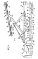
- Fig. 1 is a side view of one embodiment of a pipe handling apparatus in accordance with the present invention in an opened condition;
- Fig. 2 is a side view of the pipe handling apparatus in a partially collapsed condition;
- Fig. 3 is a partially broken side view of the pipe handling apparatus in an almost fully collapsed condition;
- Fig. 4 is an enlarged sectional view taken along lines 4-4 of Fig. 3;
- Fig. 5 is a partial longitudinal sectional view taken generally along line 5-5 of Fig. 4, but showing the pipe handling apparatus in an opened configuration and in a position for swivelling about a vertical axis; and
- Fig. 6 is a partial sectional view taken along line 6-6 of Fig. 4.
- Referring to the drawings, there is shown a
pipe handling apparatus 1 comprising achassis 3 which is adapted for over-the-road travel by the use of conventional wheel andaxle assemblies 5. Thechassis 3 is attachable to and transportable by atractor 7 in a well known manner. At least twopipe raising arms 8 are rotatably mounted to each side of the chassis. - Carried in the
chassis 3 for linear and rotational motion relative thereto is acarriage 9. Thecarriage 9 includes a base 11 which reciprocates longitudinally along the chassis withintracks vertical axis 14. Swivelling is possible only when the carriage has ascended theramps tracks platform 15 by means of ascissors lift 17. The scissors lift 17 is designed to raise and lower theplatform 15 by imparting thereto only vertical motion. When fully collapsed, theplatform 15 nests within the chassis 3 (see Figs. 3 and 4). - Supported by the
platform 15 is aconveyor 19. Theconveyor 19 is movable relative to the platform in both vertical and horizontal directions through the action of a modified scissors lift 21. Referring to Figs. 1 and 4, theconveyor 19 includes a plurality of in-line belts 23 located at the bottom of atrough 24. Thebelts 23 are driven in unison by asuitable power source 25. When the modified scissors lift 21 is fully collapsed, the conveyor nests within the platform (see Figs. 3 and 4). - To increase the horizontal range of the pipe handling apparatus, the
platform 15 is horizontally slidable to the right or left, as viewed in Figs. 1 and 5, with respect to the scissors lift 17. A horizontallyextensible brace 27 withsupport legs 29 is slidably mounted within theplatform 15, so that the platform is supported at its distal end as theplatform 15 slides off thesupport rollers 28 of the scissors lift 17. Thesupport legs 29 are pivotable so as to fold against the horizontallyextensible brace 27 when the brace is retracted into theplatform 15. To provide additional horizontal range, theconveyor 19 is also translatable relative to the modified scissors lift 21. - In operation, the
chassis 3 is parked next to a stack of pipes, not shown, so that the longitudinal axes of the pipes andchassis 3 are parallel. Theconveyor 19 andplatform 15 are completely collapsed. A pipe is rolled onto thepipe raising arms 8, and thearms 8 are swung upwardly to lift the pipe from the ground. Continued rotation of thepipe raising arms 8 cause the pipe to roll onto the top of the platform and into the trough 24 (see Fig. 4). Either or both scissors lift 17 and modified scissors lift 21 are operated to raise the conveyor so that theconveyor takeoff point 31 is near the desired height. Additional horizontal and/or vertical positioning is accomplished by moving thecarriage 9 along thechassis 3, by moving theplatform 15 on the-scissors lift 17, and by moving the conveyor on the modified scissors lift 21. If necessary to reach the derrick platform, thecarriage 9 is moved up theramps power source 25 is energized to cause thebelts 23 to axially move the pipe P, thereby enabling the rig pipe elevators, (not illustrated), to grab and lift the pipe from theconveyor 19. To return the pipe from the derrick to the stack on the ground, the foregoing procedure is essentially reversed. - The
chassis 3 is constructed as a semi-trailer, having a pair oflongitudinal beams 32 rigidly joined by cross members and having conventional wheel andaxle assemblies 5 mounted near theback end 33. Thechassis 3 is built with thebeams 32 as low to the ground as practicable. Consequently, thefront end 35 is fabricated withmembers conventional tractor 7. Under normal conditions, themembers hydraulic cylinders 42 in the angled configuration shown in Fig. 1. To the lowerside ofmember 39 is mounted a support and bearing 43 for pivotally mounting the front end of the chassis to the fifth wheel 44 to thetractor 7, as is well known. - To enable the
chassis 3 to accommodate exceptionally long pipes, theangled members Conventional outriggers 45 are mounted to each side of thechassis 3. When it is necessary to handle exceptionally long pipes, theoutriggers 45 are lowered to support thefront end 35, and thetractor 7 is driven away. Thehydraulic cylinders 42 are operated to lower themembers outriggers 45 may be used at any time when transferring pipe. - To raise a pipe from the ground onto the apparatus, a pair of
pipe raising arms 8 are rotatably mounted to the outside of eachchassis beam 32. In the construction illustrated in Figs. 1 and 4, eachpipe raising arm 8 contains aslot 47 adapted to fit over asquare shaft 49 which extends longitudinally along thechassis 3 and is supported for rotation within bearinghousings 51 mounted at intervals to the beam. Screws and nuts 53 prevent the arms from falling off thesquare shaft 49 during rotation. The square shaft can be rotated by ahydraulic motor 55 mounted to the bearinghousing 51. Having thepipe raising arms 8 connected to a common shaft facilitates raising and lowering a pipe which is not symmetrically loaded on the arms and hence which would produce unequal resistance to individual arm hydraulic circuits. The hydraulic controls for operating thehydraulic motor 55, as well as all other power mechanisms, as will be hereinafter described, are preferably located within acommon control station 56 mounted to the top ofmember 39. In addition, certain functions may be controlled from a handheld portable control box (not shown). - The inside face of each
longitudinal beam 32 supports a pair oftracks horizontal sections respective ramps upper sections - The
carriage 9 is mounted for reciprocable and swivelling motion with respect to thetracks carriage 9 includes a base 11 having a pair offront rollers 57 which ride intrack 12 and a pair ofback rollers 59 which ride intrack 10. The longitudinal spread between thefront rollers 57 and theback rollers 59 is equal to the longitudinal distance between theramps base 11 is reciprocable along thetracks ramps carriage 9 is preferably reciprocated under power, for example, by a hydraulic motor acting through a speed reducing unit and endless chain or cable (not illustrated). - Mounted on the
base 11 for swivelling about avertical axis 14 is a table 13. The table 13 is supported on the base by a circle of steel balls 61 which ride within suitable opposed grooves in thebase 11 and table 13 (see Fig. 6). Acentre post 63 connected to thebase 11 and extending vertically through the table 13 serves as a radial bearing and thereby prevents lateral movement of the table relative to the base. To prevent the possibility of the table overturning under extreme overhang conditions, the table 13 may include anannular flange 65 which slidably bears against a corresponding undersurface of thebase 11. - The
platform 15 is supported on the table 13 for vertical movement relative thereto by a scissors lift 17 (see Fig. 1). In the construction illustrated in Fig. 4, theplatform 15 is fabricated with two outer longitudinaltubular beams 75 and two inner channel beams 77. For clarity, theplatform 15 is not shown in the fully collapsed position, but rather the platform is shown in a slightly elevated condition relative to thechassis 3. For additional clarity, the clearances between some of the platform and conveyor structural members have been exaggerated. - The four
beams 75 and 77 are joined to each other on the ends of theplatform 15 by transverse braces, not shown. Each outer longitudinaltubular beam 75 is rigidly joined to the adjacent inner channel beam 77 bycross members 79 ar regular intervals along the beams. To enable a worker to walk on theplatform 15, thecross pieces 79 are covered withhardwood deckings 81. - The scissors lift 17 is preferably of conventional construction, having fixed and rolling pivot points 67 and 69, respectively, on the table, Fig. 5, and fixed and rolling pivots on the platform as will be described presently. The scissors lift 17 may be raised and lowered under the control of a pair of
hydraulic cylinders 82. - The
platform 15 is capable of horizontal motion relative to the scissors lift 17. For that purpose, at least one and preferably both inner channel beams 77 are provided with a rack 83 running longitudinally therealong (see Fig. 4). Mounted for rotation in the upper end of scissors liftarm 84 and meshing with the rack 83 is a pinion 85 (see Figs. 1 and 5). Thepinion 85 serves to support theplatform 15 on the scissors lift 17. Thepinion 85 may be driven by ahydraulic motor 87 andgear box 89. Thehydraulic motor 87 is not actuated when the scissors lift 17 is being expanded or collapsed, so that the pinion serves as a fixed pivot similar to thepivot point 67. The upper end of scissors liftarm 91 supports thesupport rollers 28 which engage tracks 95 joined to the inner channel beams 77. Thus, after theplatform 15 has been raised to the desired height, operation ofhydraulic motor 87 rotatespinion 85 and drives theplatform 15 outward toward the drill rig, which is not illustrated. It will be understood that the means for reciprocating theplatform 15 relative to the scissors lift 17 is not limited to a rack and pinion drive. For example, reciprocating motion may be accomplished through a hydraulic cylinder. In that case, thepinion 85 and rack 83 would be replaced by a roller and track assembly similar to supportrollers 28 and tracks 95. - The
platform 15 may be driven completely off thesupport rollers 28, so that only thepinions 85 support the platform on the scissors lift 17. To hold the platform in such a situation, theplatform 15 includes a horizontallyextensible brace 27 which is extendible out of the platform. The outer end of thebrace 27 is provided with pivotable ground contactingsupport legs 29 which fold up so as to be in the same plane as the horizontally extensible brace for retraction with the brace into the platform 15 (see Figs. 4 and 5). Thesupport legs 29 are vertically adjustable by any suitable means so that they support the brace regardless of height of theplatform 15 above the ground. - The
conveyor 19 is supported on theplatform 15 by a modified scissors lift 21. As illustrated in Fig. 4, theconveyor 19 includes a generallyU-shaped channel member 96. The lower end of each pair oflegs 97 of the modified scissors lift 21 is fixedly pivoted at 99 to the platform 15 (see Fig. 5). The lower end of eachleg 101 includes aroller 102 which slidably engages atrack 103 in theplatform 15.Legs common pin 104. Theupper end 113 of eachleg 101 slidably engages atrack 105 in thechannel 96 by means of a roller 106 (see Figs 2 and 4). Theupper end 111 of eachleg 97 mounts apinion 110 which meshes with arack 107 in a similar manner to that described previously in conjunction with platform rack 83 andpinion 85.Pinions 110 are driven by suitable motors andgear boxes 108. - As the modified scissors lift 21 is expanded under the action of
cylinders 109, thepinions 110, which are held against rotation by thegear boxes 108, sweep along arcs having their centers at thepivots 99. Consequently, thelegs 97 impart a horizontal components of motion to theconveyor 19. - The
upper end 111 of eachleg 97 is substantially shorter than the upper ends 113 oflegs 101. Consequently, as the modified scissors lift 21 expands, theconveyor 19 acquires a tilt upwardly toward theback end 33 of thechassis 3. The preferred angle of inclination of theconveyor 19 with the horizontal when the modified scissors lift 21 is completely expanded is about 25 degrees. To provide additional horizontal and vertical movement to theconveyor 19 with respect to the modified scissors lift 21, the motor andgear boxes 108 are actuated to rotatepinions 110. Thus, theconveyor takeoff point 31 may be extended upwardly and to the right as viewed in Figs. 1, 2 and 5. As with theplatform 15, theconveyor 19 may be reciprocated by means other than the rack and pinion, as, for example, by a hydraulic cylinder. - The
conveyor 19 includes at least two and preferably three sections of endless belts orchains 23. Referring to Figs. 1 and 4, the upper surfaces of the belts are coplanar within theU-shaped channel member 96, thereby creating atrough 24 for receiving a pipe P. The belts are connected by conventional chains andsprockets 115 for being driven in unison byhydraulic power source 25 to convey the pipe P to the derrick platform. - The purpose of the three belt conveyor is to facilitate removing the pipe from the
trough 24 during the pipe unloading operation. Referring to Figs. 2, 3 and 4, a pair ofspades 117 having taperedsurfaces 119 are removably attached to crosspieces 121 between the corresponding upper ends 111 and 113 of modified scissors lift 21. Thespades 117 are removed during the pipe loading process, but they are inserted in place during the pipe unloading process. As the modified scissors lift 21 collapses, the spades protrude into the gaps between thebelts 23. The pipe previously lying on the belts is thus raised off the belts and ejected out of the trough. The tapered surfaces 119 deflect the pipe to one side of the platform. Thespades 117 are reversible, so that the pipe being unloaded may be deflected to either side of the platform. - To operate the pipe handling apparatus described, the
chassis 3 is driven by thetractor 7 so that thechassis 3 is adjacent and parallel to a supply of pipes stacked on the ground near a drilling rig. If the pipe length requires, theoutriggers 45 are lowered to support thefront end 35 of thechassis 3, thetractor 7 is driven away, and thecylinders 42 are actuated to lower angledmembers outriggers 45 may be set up to stabilise thechassis 3 regardless of whether thetractor 7 is driven away. - The proper controls at
control station 56 are actuated to rotatehydraulic motor 55 and thereby rotatesquare shaft 49 to lower thepipe raising arms 8 on the selected side of the chassis 3 (Fig. 4). A pipe P is rolled onto thearms 8, and thearms 8 are raised so that the pipe rolls off the arms onto thehardwood decking 81 of thecollapsed platform 15. The pipe then rolls or is pushed across thedecking 81 into thetrough 24 of the collapsedconveyor 19. - The
platform 15 andconveyor 19 are manipulated through any of several of combinations of motion to position theconveyor takeoff point 31 accurately under the pipe elevator at the derrick platform. Scissors lift 17 may be operated to vertically raise theplatform 15. The horizontallyextensible brace 27 withsupport legs 29 may be pulled out of theplatform 15, thesupport legs 29 adjusted to contact the ground, and thehydraulic motor 87 actuated to move theplatform 15 horizontally off therollers 28 so that the platform is supported bylegs 29 and pinions 85. - The
carriage 9 may be moved along and up thetracks back end 33 of thechassis 3, and the table 13 may be swivelled through the desired angle. Carriage translation and swivelling would occur prior to moving theplatform 15 off therollers 28. - It is anticipated that the modified scissors lift 21 will always be operated to impart horizontal and vertical motions to the
conveyor 19. Theconveyor 19 may be translated by means ofpinions 110. When theconveyor takeoff point 31 is as close to the required location as possible, thepower source 25 is actuated to cause thebelts 23 to convey the pipe lengthwise to the derrick elevator. - To return a pipe from the derrick to the supply stack, the opposite sequence of operations is performed. However, the modified scissors lift 21 is always the last member to be collapsed. Prior to collapsing the modified scissors lift 21, the
spades 117 are attached to thecross pieces 121. As the modified scissors lift 21 approaches the fully collapsed configuration, thespades 117 enter the gaps between thebelt sections 23 to eject the pipe P from thetrough 24 and deflect the pipe to the desired side of theplatform 15. The pipe rolls across thehardwood decking 81 to theupraised arms 8, which are then operated to lower the pipe to the ground. Several pipes can be stored on thehardwood decking 81 when loading and unloading pipe, hence, the equipment does not have to be fully collapsed for each pipe being transferred. Railings (not shown) can be employed to contain the pipes on thehardwood decking 81.
Claims (22)
characterized in that:
characterized in that the platform means (15) is adapted to nest within the chassis when in the lowered position; and
Priority Applications (1)
| Application Number | Priority Date | Filing Date | Title |
|---|---|---|---|
| AT85306752T ATE43402T1 (en) | 1984-09-24 | 1985-09-23 | LOADING DEVICE FOR PIPES. |
Applications Claiming Priority (2)
| Application Number | Priority Date | Filing Date | Title |
|---|---|---|---|
| US654199 | 1984-09-24 | ||
| US06/654,199 US4684314A (en) | 1984-09-24 | 1984-09-24 | Pipe handling apparatus |
Publications (2)
| Publication Number | Publication Date |
|---|---|
| EP0176335A1 EP0176335A1 (en) | 1986-04-02 |
| EP0176335B1 true EP0176335B1 (en) | 1989-05-24 |
Family
ID=24623857
Family Applications (1)
| Application Number | Title | Priority Date | Filing Date |
|---|---|---|---|
| EP85306752A Expired EP0176335B1 (en) | 1984-09-24 | 1985-09-23 | Pipe handling apparatus |
Country Status (6)
| Country | Link |
|---|---|
| US (1) | US4684314A (en) |
| EP (1) | EP0176335B1 (en) |
| AT (1) | ATE43402T1 (en) |
| CA (1) | CA1257881A (en) |
| DE (1) | DE3570482D1 (en) |
| NO (1) | NO853754L (en) |
Families Citing this family (99)
| Publication number | Priority date | Publication date | Assignee | Title |
|---|---|---|---|---|
| US4907935A (en) * | 1987-12-04 | 1990-03-13 | Standard Manufacturing Company, Inc. | Cargo transporter |
| US5122023A (en) * | 1991-02-13 | 1992-06-16 | Nabors Industries, Inc. | Fully articulating ramp extension for pipe handling apparatus |
| FR2682069A1 (en) * | 1991-10-08 | 1993-04-09 | Faivre Jacques | TURRET FOR A MATERIAL TRANSPORT VEHICLE AND TELESCOPIC CONVEYOR MOUNTED ON SUCH A TURRET. |
| US5451134A (en) * | 1991-10-22 | 1995-09-19 | Bryfogle; Mark D. | Material handling devices and controllers |
| US5394959A (en) * | 1992-12-15 | 1995-03-07 | Simon Aerials, Inc. | Scissor lift apparatus for work platforms and the like |
| GB2322348B (en) * | 1995-12-29 | 2001-02-14 | Australian Longwall Pty Ltd | A conveyor assembly |
| US5979642A (en) * | 1997-02-19 | 1999-11-09 | Australian Longwall Pty Limited | Extendable modular conveyor assembly |
| US6079925A (en) * | 1998-06-19 | 2000-06-27 | Morgan; Carl | Method and apparatus for lifting oilfield goods to a derrick floor |
| MXPA01002891A (en) * | 2000-03-21 | 2002-04-24 | M Lutz David | Expandable over and under line feed system. |
| US6877942B2 (en) * | 2000-04-18 | 2005-04-12 | Circle T Service & Rental Ltd. | Ramp trailer for oil field tubulars |
| AT410355B (en) * | 2000-05-17 | 2003-04-25 | Voest Alpine Bergtechnik | DEVICE FOR EXTENDING OR SHORTING PIPELINES |
| US6598702B1 (en) * | 2000-07-13 | 2003-07-29 | Mcgillewie, Jr. Garth E. | Under bridge access apparatus with cross-linking member connecting tower with vehicular chassis |
| US20030196791A1 (en) * | 2002-02-25 | 2003-10-23 | N-I Energy Development, Inc. | Tubular handling apparatus and method |
| US6974123B2 (en) | 2002-04-03 | 2005-12-13 | Advance Lifts, Inc. | Platform centering device |
| NL1020310C2 (en) * | 2002-04-04 | 2003-10-07 | Huisman Spec Lifting Equip Bv | Offshore drilling, comprises use of rotary drill head at end of fixed drill strand clamped on at least three sides by clamp conveyor |
| WO2003093629A1 (en) * | 2002-05-03 | 2003-11-13 | Weatherford/Lamb, Inc. | Height-adjustable pipe pick-up and laydown machine |
| US6752244B2 (en) * | 2002-08-16 | 2004-06-22 | Sheppard Holdings Ltd. | Apparatus for draining fluids from vehicles |
| US7357616B2 (en) * | 2003-01-30 | 2008-04-15 | Doyon Drilling, Inc. | Method and apparatus for transporting oil rig |
| CA2444446C (en) * | 2003-10-10 | 2010-06-01 | Custom Pipe Handlers Inc. | Multi-position height adjustment system for a pipe handling apparatus |
| US6994505B2 (en) * | 2004-01-09 | 2006-02-07 | Frank's International | Pick-up and lay-down system and method |
| US8191865B2 (en) | 2004-05-17 | 2012-06-05 | Stertil B.V. | Device and system for lifting a motor vehicle |
| US20080008561A1 (en) * | 2004-06-07 | 2008-01-10 | Hontz Carl O Jr | Self-adjusting drywall crane |
| US7540700B2 (en) * | 2004-06-17 | 2009-06-02 | Deere & Company | Grain cart with intermodal container loader |
| US20060045653A1 (en) * | 2004-07-16 | 2006-03-02 | Guidry Mark L | Pick-up and lay-down system and method |
| US7635249B2 (en) * | 2004-08-18 | 2009-12-22 | Guidroz Perry J | Pipe pick-up and laydown apparatus |
| US20060151252A1 (en) * | 2004-11-01 | 2006-07-13 | Spx Corporation | Heavy duty vehicle component lift apparatus and method |
| US7350587B2 (en) * | 2004-11-30 | 2008-04-01 | Varco I/P, Inc. | Pipe guide |
| CA2489877A1 (en) * | 2004-12-13 | 2006-06-13 | Cheryl Gust | Mobile pipe handler and stacker |
| US7614492B2 (en) * | 2005-11-18 | 2009-11-10 | Pop's Laydown Service, L.L.C. | Methods and systems of handling pipe |
| CA2535083C (en) * | 2006-02-01 | 2010-12-14 | Gerald Lesko | Pipe indexer/kicker |
| US20070286708A1 (en) * | 2006-06-09 | 2007-12-13 | Columbia Trailer Co., Inc. | Method and apparatus for handling pipe |
| WO2008022424A1 (en) | 2006-08-24 | 2008-02-28 | Canrig Drilling Technology Ltd. | Oilfield tubular torque wrench |
| CA2661405C (en) | 2006-08-25 | 2013-01-08 | Canrig Drilling Technology Ltd. | Methods and apparatus for automated oilfield torque wrench set-up to make-up and break-out tubular strings |
| US8074537B2 (en) | 2006-09-08 | 2011-12-13 | Canrig Drilling Technology Ltd. | Oilfield tubular spin-in and spin-out detection for making-up and breaking-out tubular strings |
| US20090000218A1 (en) * | 2007-06-28 | 2009-01-01 | Douglas Wayne Lee | Land rig |
| WO2009026205A2 (en) * | 2007-08-20 | 2009-02-26 | Maltby Scott R | Portable drill pipe handling apparatus for use with oil and gas well drilling rigs |
| US7568533B2 (en) * | 2007-11-16 | 2009-08-04 | Rodger Lawrence Felt | Pipehandler |
| US7845498B2 (en) * | 2007-12-04 | 2010-12-07 | John Kauffman | Separation of metals from sand |
| US8157495B1 (en) * | 2008-01-30 | 2012-04-17 | Astec Industries, Inc. | Apparatus and method for a pipe handler |
| US8813436B2 (en) | 2008-02-29 | 2014-08-26 | National Oilwell Varco, L.P. | Pinned structural connection using a pin and plug arrangement |
| US8549815B2 (en) * | 2008-02-29 | 2013-10-08 | National Oilwell Varco L.P. | Drilling rig masts and methods of assembly and erecting masts |
| US8250816B2 (en) | 2008-02-29 | 2012-08-28 | National Oilwell Varco L.P. | Drilling rig structure installation and methods |
| US8047303B2 (en) * | 2008-02-29 | 2011-11-01 | National Oilwell Varco L.P. | Drilling rig drawworks installation |
| US8468753B2 (en) * | 2008-02-29 | 2013-06-25 | National Oilwell Varco L.P. | Drilling rigs and erection methods |
| US8516751B2 (en) * | 2008-05-15 | 2013-08-27 | National Oilwell Varco L.P. | Mobile drilling rig |
| US8240968B2 (en) * | 2008-10-27 | 2012-08-14 | Laibe Corporation | Automated rod handling system |
| US8505684B1 (en) | 2009-02-05 | 2013-08-13 | Marc Bogue | Aerial work platform apparatus and method |
| WO2011011887A1 (en) * | 2009-07-29 | 2011-02-03 | Markwater International B.V. | Pipe kicker/indexer for pipe handling systems |
| US20110226466A1 (en) * | 2010-03-19 | 2011-09-22 | Baker Hughes Incorporated | Electric Submersible Pump Service Truck |
| CA2713051C (en) * | 2010-08-13 | 2019-02-26 | Vince Morelli | Pipe handling system, apparatus and method |
| US8899901B2 (en) * | 2012-06-14 | 2014-12-02 | Warrior Energy Services Corporation | Pipe handling apparatus and method |
| US9267342B2 (en) | 2012-06-14 | 2016-02-23 | Warrior Energy Services Corporation | Pipe handling apparatus and method |
| US8950996B2 (en) * | 2012-06-14 | 2015-02-10 | Warrior Energy Services Corporation | Pipe handling apparatus and method |
| US9091125B2 (en) | 2012-01-16 | 2015-07-28 | National Oilwell Varco, L.P. | Collapsible substructure for a mobile drilling rig |
| CN102536139B (en) * | 2012-02-13 | 2014-04-09 | 常州大学 | Movement mechanism for conveying drill columns for drilling platform |
| US9080397B2 (en) * | 2012-03-21 | 2015-07-14 | Darcy LUDWIG | Pipe handling apparatus |
| AU2013243236A1 (en) * | 2012-04-04 | 2014-11-20 | John Nitschke Nominees Pty Ltd | Conveyor for use with a drill pipe storage sloop |
| US20130279982A1 (en) * | 2012-04-24 | 2013-10-24 | ShoreMaster, LLC | Watercraft Lift System |
| US8807323B2 (en) | 2012-05-17 | 2014-08-19 | A. G. Stacker, Inc. | Conveyor having bottom opening for accommodating a conveyor support structure and method of using same |
| US9109394B2 (en) * | 2012-06-01 | 2015-08-18 | Pablo Hernandez | Adjustable ladder support mechanism |
| US9388647B2 (en) | 2012-08-15 | 2016-07-12 | Liberty Holdings, LLC | Pipe handler |
| US9187269B2 (en) | 2012-10-12 | 2015-11-17 | Chevron Phillips Chemical Company Lp | Polymeric pipe loading |
| WO2014193228A2 (en) * | 2013-05-27 | 2014-12-04 | Itrec B.V. | Drilling vessel |
| US9725970B1 (en) * | 2013-09-18 | 2017-08-08 | CRW Contracting, Inc. | Compact pipe handling trailer |
| US9506303B2 (en) * | 2014-03-17 | 2016-11-29 | Vektor Lift, Llc | Method and apparatus for pipe pickup and laydown |
| DE102014209016A1 (en) | 2014-05-13 | 2015-11-19 | Siemens Aktiengesellschaft | A tiltable patient support apparatus and method for tilting a patient support apparatus |
| US9522625B2 (en) | 2014-05-30 | 2016-12-20 | Troy A. Myers | Boat loading allignment device and method |
| US9624740B2 (en) * | 2014-06-26 | 2017-04-18 | Tammy Sue Molski | Hydraulic pipe handling apparatus |
| US9695024B2 (en) | 2015-01-23 | 2017-07-04 | Jeremy Herauf | Unique roadworthy sidewalk boom trailer, having on-site interchangeable boom, on-site interchangeable ladder, and on-site interchangeable catwalk sized to access narrow openings and nooks over and under bridges |
| CN104533318B (en) * | 2015-01-30 | 2017-02-22 | 杨若森 | Automatic oil pipe dismounting device |
| US10221634B2 (en) * | 2015-04-14 | 2019-03-05 | Nabors Drilling Technologies Usa, Inc. | Catwalk system and method |
| CA2933874C (en) * | 2015-06-24 | 2022-05-17 | Coax Technology Inc. | System and method for delivering a tubular pipe segment to a drill rig floor |
| US9549505B1 (en) * | 2015-09-21 | 2017-01-24 | Deere & Company | Agricultural vehicle conveyance linkage |
| CN105781450B (en) * | 2016-03-21 | 2017-12-08 | 杨发 | Split type hydraulic lifts and automatic push oil pipe slideway |
| CN106593325B (en) * | 2016-11-25 | 2018-02-02 | 山东瑞奥智能设备有限责任公司 | Oil drilling machine packaged type rig floor pipe arranging robot |
| WO2018175376A1 (en) * | 2017-03-24 | 2018-09-27 | Bedgear, Llc | Zero gravity bed |
| US10508507B2 (en) * | 2017-11-15 | 2019-12-17 | Forum Us, Inc. | Tubular transfer system with variable presentation height and presentation angle |
| RU182891U1 (en) * | 2018-02-19 | 2018-09-05 | федеральное государственное бюджетное образовательное учреждение высшего образования "Волгоградский государственный аграрный университет" (ФГБОУ ВО Волгоградский ГАУ) | LIFT FOR CARRYING LOADS |
| CN108545403B (en) * | 2018-03-16 | 2020-07-10 | 福州宏毓建材有限公司 | Brick conveying equipment for building |
| US10494177B1 (en) | 2018-07-20 | 2019-12-03 | Amada America, Inc. | Modular system and method for material storage and conveying |
| US10920504B1 (en) | 2018-07-20 | 2021-02-16 | Hawker Equipment Solutions, LLC. | Pipe grabber |
| US10626687B1 (en) | 2018-09-14 | 2020-04-21 | Hawker Equipment Solutions, LLC. | Wedge system to extend and elevate a pipe handler |
| US10662725B1 (en) | 2018-11-05 | 2020-05-26 | Superior Rig Innovations Ltd. | Tubular handling apparatus and methods |
| CN109592340B (en) * | 2018-11-26 | 2024-03-22 | 浙江湖州中盟智能科技有限公司 | Foldable support leg for logistics conveying line |
| CN109736703B (en) * | 2019-02-21 | 2024-07-02 | 中铁九局集团电务工程有限公司 | Tunnel puncher |
| AU2020254332B2 (en) * | 2019-04-05 | 2024-06-20 | Oshkosh Corporation | Scissor lift descent control systems and methods |
| US11865960B2 (en) * | 2019-10-09 | 2024-01-09 | New Heights, Llc | Material delivery and waste removal trailer |
| CN111071704B (en) * | 2020-03-04 | 2021-07-16 | 南京港龙潭集装箱有限公司 | Intelligent port loading and unloading conveying equipment |
| US11279564B1 (en) | 2021-03-24 | 2022-03-22 | A. G. Stacker Inc. | Conveyor having at least one flexible belt and method of tensioning the at least one belt |
| CN113417583B (en) * | 2021-08-04 | 2024-09-17 | 西安荣拓石油装备技术有限公司 | Lifting device for movable drill rod |
| CN114183083B (en) * | 2021-12-14 | 2023-11-28 | 安徽理工大学 | Automatic migration device of modular drill rod |
| US11885180B2 (en) * | 2022-01-18 | 2024-01-30 | Charles J. Mackarvich | Modular ladder system |
| CN114809955B (en) * | 2022-04-22 | 2025-08-29 | 英特莱福(青岛)海洋装备技术有限公司 | An automated hydraulic lifting oil pipe conveyor |
| CN115159003A (en) * | 2022-06-30 | 2022-10-11 | 中国一冶集团有限公司 | Method for transporting jacking pipe joints in limited space |
| CN115123963B (en) * | 2022-07-08 | 2025-02-18 | 中国建筑一局(集团)有限公司 | A rotating boom type pipe handling lifting vehicle and a method of using the same |
| CN115123962B (en) * | 2022-07-08 | 2025-01-14 | 中国建筑一局(集团)有限公司 | Inclined pipeline carrying lifting vehicle and application method thereof |
| CN115771862B (en) * | 2022-11-30 | 2024-07-26 | 中国化学工程第六建设有限公司 | Construction process for clean pipeline of lithium battery positive factory building |
| CN116513980B (en) * | 2023-05-04 | 2024-05-14 | 江苏中贵重工有限公司 | Pipeline installation device |
| CN118187710B (en) * | 2024-05-20 | 2024-07-19 | 新疆青蓝科技有限公司 | Pipe rod delivery device |
Family Cites Families (42)
| Publication number | Priority date | Publication date | Assignee | Title |
|---|---|---|---|---|
| US711008A (en) * | 1902-03-08 | 1902-10-14 | Alexander Anderson Scott | Elevating-truck. |
| US1139891A (en) * | 1914-07-03 | 1915-05-18 | Carl E M Miller | Lifting-truck. |
| US1423878A (en) * | 1920-07-19 | 1922-07-25 | Potter Laurens Day | Loader device |
| US1826116A (en) * | 1927-04-14 | 1931-10-06 | Andrews Crane Corp | Lift-platform truck |
| US2617547A (en) * | 1949-11-14 | 1952-11-11 | Whetstine B Pridy | Pipe loading device |
| US2676715A (en) * | 1952-04-16 | 1954-04-27 | Whetstine B Pridy | Self-loading truck for heavy pipe |
| US2931519A (en) * | 1954-10-28 | 1960-04-05 | Lockheed Aircraft Corp | Aircraft component dolly |
| US2900091A (en) * | 1955-12-05 | 1959-08-18 | John O Minter | Pipe handling equipment |
| US2922533A (en) * | 1957-12-30 | 1960-01-26 | Labarge Pipe And Steel Company | Lift |
| US3103291A (en) * | 1960-12-23 | 1963-09-10 | Anthony L Cresci | Load carrying vehicle |
| US3168206A (en) * | 1962-12-13 | 1965-02-02 | Nat Homes Corp | Trailer |
| US3268095A (en) * | 1964-04-06 | 1966-08-23 | J W Durbin | Pipe racking device |
| US3259255A (en) * | 1964-05-08 | 1966-07-05 | Paul A Cresci | Tilting body for motor vehicles |
| US3315822A (en) * | 1965-10-04 | 1967-04-25 | Wilson Mfg Co | Drill stem and pipe positioner device |
| DE1267166B (en) * | 1966-02-09 | 1968-04-25 | Luebecker Maschb Ag | Elevation conveyor |
| US3446379A (en) * | 1967-10-17 | 1969-05-27 | Leco Inc | High-lift elevating mechanism |
| US3499498A (en) * | 1968-03-11 | 1970-03-10 | Kendrick Cattle Co | Pipe racking and transfer assembly |
| US3599784A (en) * | 1968-12-16 | 1971-08-17 | Lionello Rossi | Automotive continuous conveyor of an articulated type |
| US3559821A (en) * | 1969-06-19 | 1971-02-02 | Ralph Edward James | Drill pipe handling apparatus |
| US3706347A (en) * | 1971-03-18 | 1972-12-19 | Cicero C Brown | Pipe handling system for use in well drilling |
| US3780883A (en) * | 1971-03-18 | 1973-12-25 | Brown Oil Tools | Pipe handling system for use in well drilling |
| US3792783A (en) * | 1971-03-18 | 1974-02-19 | C Brown | Pipe handling system |
| US3785506A (en) * | 1971-09-10 | 1974-01-15 | Roger A Crocker | Drill pipe handling apparatus |
| US3916500A (en) * | 1972-05-24 | 1975-11-04 | Cicero C Brown | Pipe handling apparatus |
| US3810553A (en) * | 1972-08-31 | 1974-05-14 | R Crocker | Pipe handling device |
| US4054210A (en) * | 1975-09-29 | 1977-10-18 | Crocker Roger A | Apparatus for transporting and handling pipe |
| US4070807A (en) * | 1977-01-12 | 1978-01-31 | Smith Raymond E Jun | Aerial lift |
| US4236861A (en) * | 1978-09-25 | 1980-12-02 | Jlg Industries, Inc. | Scissors lift with pipe handler |
| US4235566A (en) * | 1978-12-04 | 1980-11-25 | Beeman Archie W | Pipe-conveying catwalk |
| FR2449057A1 (en) * | 1979-02-19 | 1980-09-12 | Sovam | Trolley with scissor lift - is used to position load and pivotal about horizontal and vertical axes |
| US4347028A (en) * | 1979-09-17 | 1982-08-31 | Automatic Pipe Racker, Inc. | Pipe handling apparatus |
| US4382738A (en) * | 1980-02-27 | 1983-05-10 | Ingram Corporation | Pipe handling system |
| US4470740A (en) * | 1980-09-10 | 1984-09-11 | Ingram Corporation | Apron for pipe handling system |
| US4426182A (en) * | 1980-09-10 | 1984-01-17 | Ingram Corporation | Tubular handling apparatus |
| US4371302A (en) * | 1980-09-30 | 1983-02-01 | Ingram Corporation | Pipe handling apparatus |
| US4386883A (en) * | 1980-09-30 | 1983-06-07 | Rig-A-Matic, Inc. | Materials lifting apparatus |
| US4491449A (en) * | 1981-05-05 | 1985-01-01 | John J. Kirlin | Load raising vehicle and method |
| US4491450A (en) * | 1981-09-23 | 1985-01-01 | George Albert L | Pick-up and laydown machine |
| US4453872A (en) * | 1981-12-07 | 1984-06-12 | Ingram Corporation | Handling apparatus for pipe and other tubulars |
| US4403898A (en) * | 1981-12-31 | 1983-09-13 | Thompson Carroll R | Pipe pick-up and laydown machine |
| US4474520A (en) * | 1982-03-02 | 1984-10-02 | Ingram Corporation | Pipe handling machine |
| US4552498A (en) * | 1983-05-02 | 1985-11-12 | Branham Industries, Inc. | Pickup and lay-down apparatus |
-
1984
- 1984-09-24 US US06/654,199 patent/US4684314A/en not_active Expired - Fee Related
-
1985
- 1985-09-23 DE DE8585306752T patent/DE3570482D1/en not_active Expired
- 1985-09-23 EP EP85306752A patent/EP0176335B1/en not_active Expired
- 1985-09-23 AT AT85306752T patent/ATE43402T1/en not_active IP Right Cessation
- 1985-09-24 NO NO853754A patent/NO853754L/en unknown
- 1985-09-24 CA CA000491392A patent/CA1257881A/en not_active Expired
Also Published As
| Publication number | Publication date |
|---|---|
| ATE43402T1 (en) | 1989-06-15 |
| EP0176335A1 (en) | 1986-04-02 |
| CA1257881A (en) | 1989-07-25 |
| US4684314A (en) | 1987-08-04 |
| NO853754L (en) | 1986-03-25 |
| DE3570482D1 (en) | 1989-06-29 |
Similar Documents
| Publication | Publication Date | Title |
|---|---|---|
| US4684314A (en) | Pipe handling apparatus | |
| CN104136708B (en) | A device for conveying drill pipe to a drilling rig | |
| CN111511672B (en) | Tray racking equipment | |
| US3795336A (en) | Apparatus for transporting building modules | |
| US6719515B2 (en) | Pipe handling apparatus | |
| US7604134B2 (en) | Portable knockdown trolley hoist | |
| US6079925A (en) | Method and apparatus for lifting oilfield goods to a derrick floor | |
| US3850283A (en) | Air cargo container loader | |
| US3501027A (en) | Pipe racking and transfer assembly | |
| US8950996B2 (en) | Pipe handling apparatus and method | |
| EP0312286A2 (en) | Folded/telescoped drill rig mast for limited space platform | |
| US20080138174A1 (en) | Pick-up and lay-down system and method | |
| US3795326A (en) | Apparatus for handling drill pipe | |
| US3220585A (en) | High lift trailer | |
| US20220176883A1 (en) | Vehicle Cargo Rack System with Powered Lift | |
| US4875547A (en) | Portable conveyor system with telescopic boom assembly and load carrying apparatus | |
| US3313429A (en) | Vehicle loading and unloading apparatus | |
| JP6566996B2 (en) | Transfer device and cargo handling vehicle | |
| US4645406A (en) | Container loader and transport assembly | |
| US3471047A (en) | Pallet loading apparatus | |
| CA2982786C (en) | Catwalk system and method | |
| US20040131449A1 (en) | Pipe handling apparatus for pick-up and lay-down machine | |
| GB2161523A (en) | Cantilever drilling structure | |
| US3822077A (en) | Fitting for lifting cargo containers | |
| US3458055A (en) | Portable pipe-handling apparatus |
Legal Events
| Date | Code | Title | Description |
|---|---|---|---|
| PUAI | Public reference made under article 153(3) epc to a published international application that has entered the european phase |
Free format text: ORIGINAL CODE: 0009012 |
|
| AK | Designated contracting states |
Kind code of ref document: A1 Designated state(s): AT DE FR GB IT NL |
|
| 17P | Request for examination filed |
Effective date: 19860312 |
|
| 17Q | First examination report despatched |
Effective date: 19870505 |
|
| D17Q | First examination report despatched (deleted) | ||
| GRAA | (expected) grant |
Free format text: ORIGINAL CODE: 0009210 |
|
| ITF | It: translation for a ep patent filed | ||
| AK | Designated contracting states |
Kind code of ref document: B1 Designated state(s): AT DE FR GB IT NL |
|
| REF | Corresponds to: |
Ref document number: 43402 Country of ref document: AT Date of ref document: 19890615 Kind code of ref document: T |
|
| REF | Corresponds to: |
Ref document number: 3570482 Country of ref document: DE Date of ref document: 19890629 |
|
| ET | Fr: translation filed | ||
| PGFP | Annual fee paid to national office [announced via postgrant information from national office to epo] |
Ref country code: AT Payment date: 19900711 Year of fee payment: 6 |
|
| PGFP | Annual fee paid to national office [announced via postgrant information from national office to epo] |
Ref country code: FR Payment date: 19900731 Year of fee payment: 6 |
|
| ITTA | It: last paid annual fee | ||
| PGFP | Annual fee paid to national office [announced via postgrant information from national office to epo] |
Ref country code: NL Payment date: 19900930 Year of fee payment: 6 |
|
| PGFP | Annual fee paid to national office [announced via postgrant information from national office to epo] |
Ref country code: GB Payment date: 19910729 Year of fee payment: 7 |
|
| PGFP | Annual fee paid to national office [announced via postgrant information from national office to epo] |
Ref country code: DE Payment date: 19910808 Year of fee payment: 7 |
|
| PG25 | Lapsed in a contracting state [announced via postgrant information from national office to epo] |
Ref country code: AT Effective date: 19910923 |
|
| PLBE | No opposition filed within time limit |
Free format text: ORIGINAL CODE: 0009261 |
|
| STAA | Information on the status of an ep patent application or granted ep patent |
Free format text: STATUS: NO OPPOSITION FILED WITHIN TIME LIMIT |
|
| 26N | No opposition filed | ||
| PG25 | Lapsed in a contracting state [announced via postgrant information from national office to epo] |
Ref country code: NL Effective date: 19920401 |
|
| NLV4 | Nl: lapsed or anulled due to non-payment of the annual fee | ||
| PG25 | Lapsed in a contracting state [announced via postgrant information from national office to epo] |
Ref country code: FR Effective date: 19920529 |
|
| REG | Reference to a national code |
Ref country code: FR Ref legal event code: ST |
|
| PG25 | Lapsed in a contracting state [announced via postgrant information from national office to epo] |
Ref country code: GB Effective date: 19920923 |
|
| GBPC | Gb: european patent ceased through non-payment of renewal fee |
Effective date: 19920923 |
|
| PG25 | Lapsed in a contracting state [announced via postgrant information from national office to epo] |
Ref country code: DE Effective date: 19930602 |