EP0312286A2 - Folded/telescoped drill rig mast for limited space platform - Google Patents
Folded/telescoped drill rig mast for limited space platform Download PDFInfo
- Publication number
- EP0312286A2 EP0312286A2 EP88309475A EP88309475A EP0312286A2 EP 0312286 A2 EP0312286 A2 EP 0312286A2 EP 88309475 A EP88309475 A EP 88309475A EP 88309475 A EP88309475 A EP 88309475A EP 0312286 A2 EP0312286 A2 EP 0312286A2
- Authority
- EP
- European Patent Office
- Prior art keywords
- mast
- section
- guide rail
- transfer frame
- drill rig
- Prior art date
- Legal status (The legal status is an assumption and is not a legal conclusion. Google has not performed a legal analysis and makes no representation as to the accuracy of the status listed.)
- Withdrawn
Links
Images


Classifications
-
- E—FIXED CONSTRUCTIONS
- E21—EARTH DRILLING; MINING
- E21B—EARTH DRILLING, e.g. DEEP DRILLING; OBTAINING OIL, GAS, WATER, SOLUBLE OR MELTABLE MATERIALS OR A SLURRY OF MINERALS FROM WELLS
- E21B15/00—Supports for the drilling machine, e.g. derricks or masts
-
- E—FIXED CONSTRUCTIONS
- E21—EARTH DRILLING; MINING
- E21B—EARTH DRILLING, e.g. DEEP DRILLING; OBTAINING OIL, GAS, WATER, SOLUBLE OR MELTABLE MATERIALS OR A SLURRY OF MINERALS FROM WELLS
- E21B15/00—Supports for the drilling machine, e.g. derricks or masts
- E21B15/003—Supports for the drilling machine, e.g. derricks or masts adapted to be moved on their substructure, e.g. with skidding means; adapted to drill a plurality of wells
Landscapes
- Engineering & Computer Science (AREA)
- Life Sciences & Earth Sciences (AREA)
- Geology (AREA)
- Mining & Mineral Resources (AREA)
- Mechanical Engineering (AREA)
- Physics & Mathematics (AREA)
- Environmental & Geological Engineering (AREA)
- Fluid Mechanics (AREA)
- General Life Sciences & Earth Sciences (AREA)
- Geochemistry & Mineralogy (AREA)
- Earth Drilling (AREA)
Abstract
A folding telescoped drill rig mast (10) having wheel assemblies which travel along the power swivel guide rail to guide the telescoped upper mast (39) as it retracts or extends within the lower mast (30). The fully extended upper mast (39) locks into a transfer frame (70) which moves laterally relative to the lower mast (30) between a first position with the upper guide rail (72) offset from the lower guide rail (52) to a second position with the upper guide rail (72) in longitudinal alignment with the lower guide rail (52). This lateral movement aligning the upper and lower masts (39, 30) enables pinning the upper and lower masts together to transfer the upper mast loading to the support members of the lower mast. The mast includes a base structure (33), a lower mast (30) with a guide rail (52), and an upper mast (39) held within the lower mast (30). The upper mast (39) includes a guide rail (72) for the power swivel. A dolly wheel assembly (85, 86) mounts to the upper mast (39) and engages the lower guide rail (52) to guide the upper mast (39) as it travels between a first position within the lower mast (30) to a second extended position. A transfer frame (70) at the free end of the lower mast (30) connects rigidly to the upper mast (39). The transfer frame (70) and the upper mast (39) are moved laterally relative to the lower mast (30) to align the upper and lower masts (39, 30) and the upper and lower power swivel guide rails (72, 52).
Description
- The present invention relates to folded telescoped mast drilling rigs. More particularly, the present invention relates to a method and apparatus for erecting a folded lower mast and a telescoped upper mast to elevated operating positions on a drill platform, locking the upper mast to a transfer frame, and moving the transfer frame to a position to align upper and lower guide rails for the power swivel and to transfer the load of the upper mast to the lower mast support structure.
- Various folded or telescoped mast drilling rigs may be used in either land or ocean based drilling operations. For desert or other land operations, the folded mast may be supported from a trailer truck for transporting the rig to the drill site. Typically, the folded mast section extends from its pivot point above the rear portion of the trailer towards the front end of the trailer.
- There are various systems which may be employed to erect a lower mast and a pivotally connected upper mast to a vertical position. Hydraulic rams are commonly used to unfold the lower and upper masts together. In other systems a line reeved through sheaves on the mast sections connect to a drawworks which winds the line on a cable reel. Pulling the line pulls the mast into an erect operating position.
- United States Patent No. 3,295,270 issued to Woolslayer, et al. describes a two-section folded oil well mast structure. The back sides of the two sections hinge together permitting the upper mast to fold over the lower mast. In this apparatus the mast structure erects into a vertical operating position by winding a line onto a drawworks cable reel. The line extends along the lower mast and over the pivot hinge to a traveling block near the pivot point. A hook on the traveling block connects to a sling which connects between the lower and the upper mast sections. Winding the line on a cable reel moves the travelling block towards the front of the mast. The hook pulls on the fixed sling to swing the mast sections to an erect position.
- United States Patent 4,134,237 issued to Armstrong describes a modular section mast having telescoped modular mast sections which are inserted at remote land sites or on an offshore platform by a small capacity crane into the open side of the U-shaped lower mast. The upper mast is inserted and raised by cable in the erect lower mast. The intermediate mast is inserted and secured to the lower end of the upper mast. Removable retainer plates guide the upper and intermediate mast sections within the lower mast when being extended by pulling on a pulling line. After the mast is fully erected, the structures are bolted together.
- United States Patent No. 4,393,630 issued to Knox describes a truck mounted telescoping well mast structure which pivotally connects at its lower end to a truck. The mast structure folds over the truck from its pivotal connection at the rear of the truck. In raising the mast, the lower mast structure pivots from a horizontal position to a vertical position. The upper telescope structure then slides or moves upwardly on bearing pads permitting reciprocal travel of the upper structure relative to the lower structure. The upper mast may be extended and retracted by a hydraulic cylinder. A trolly having wheels moves along the inside edge of a vertical member of the lower mast section. The trolly is secured within a housing at the upper end of the lower section by an elongated track connected to the upper section. Securing the trolly locks a cable to allow the racking platform to extend.
- United States Patent No. 2,804,948 issued to Woolslayer, et al. describes a telescoping portable mast having two sections. The lower end of the mast is hinged so that the mast may swing to a horizontal reclining position. The legs of the upper mast have tongues which insert axially into forks on the lower mast. The legs then rigidly connect by splice pins. The legs of the lower section serve as guide rails for grooved wheels to support and guide the upper section when it extends or retracts.
- United States Patent No. 2,804,949 issued to Woolslayer, et al. describes a two-section telescoping portable mast hinged at its lower end to enable a mast to swing to a substantially horizontal position. The legs of the upper mast have tongues which insert axially into forks on the lower mast. The legs are rigidly connected by splice pins. A trolly roller suspended from the top of the lower section engages a rail extending longitudinally along the upper section. The roller and rail cooperate to guide the extension and retraction of the upper mast.
- While folded and telescoped masts provide mobility and stability during transportation, these masts must be secured to withstand the stresses of the mast. During drilling operations, the frame members for the mast sections must be aligned and secured by pinning or other means to transmit the loading on the mast to the mast support structure.
- United States Patent No. 2,336,432 issued to Wilson describes a two-section telescoped oil well mast having corner angle members that are aligned axially. These members laterally support and guide the upper mast section. After the telescoped mast is fully extended, the adjacent portions of the upper and lower mast sections are wedged together to secure the upper mast to the lower mast. It is of concern, however, that this wedging and locking is not able to withstand a significant backlash from the drilling operation. In that situation, the upper and lower sections of the mast may separate causing destruction of the mast and dangerous operating conditions for the drillers.
- Some of these folded and telescoped masts also do not appear adapted to advantageously employ a power swivel for turning the drill string. The present invention enables a compact drill rig mast to use a power swivel for drilling operations. The power swivel is a relatively recent advance in drilling technology. Dolly wheels connected to the power swivel housing run on a pair of flanged guide rails to resist torque and to keep the power swivel aligned with the well centerline. Use of guide rails permits more rapid vertical movement of the traveling block which is suspended from the drawworks cable. A drill rig using a folded or a telescoped mast and a power swivel would have to align the power swivel guide rail in the various mast sections to permit drilling activity.
- In accordance with the present invention there is disclosed a folded telescoped mast drilling system which addresses the disadvantages of drill masts known in the industry. The system of the present invention provides rail guided raising and lowering of the upper mast, alignment of the mast support members and the power swivel guide rail, and secure connection of the upper and lower masts for transferring the load from the mast to the mast support structure.
- Apparatus constructed in accordance with the teachings of the present invention provide for the secure connecting of the upper and lower mast sections so that loads are transmitted safely from the mast to the mast support structure. Further, the raising and lowering of the upper mast is stabilized by dolly wheel assemblies traveling on the rails of the power swivel guide. This reduces the need for mast support members slideably contacting each other during the erection process, and thus minimizes unnecessary damage during assembly and disassembly of the mast. Once the upper mast is fully erected, it is locked into a transfer frame at the upper end of the lower mast. The transfer frame then moves laterally with respect to the lower mast from a first forward position to a second back position. This movement aligns the upper and lower guide rails for the power swivel. The upper and lower masts are then pinned together for added strength and stability of the erected operating drill mast.
- Offshore platforms typically are floated to an ocean drill site and then anchored to the sea bottom. The base structure is installed and a conventional derrick assembled member-by-member at the drill site. Offshore platform installation is expensive, dangerous, and time consuming. Installing a derrick on an offshore platform involves relatively dangerous work for the crew performed at the ocean site over a several week or more period. A folded telescoped mast would reduce the assembly risks and time by enabling the mast to be assembled on land and barged to the anchored platform. A heavy crane on another barge may then hoist the mast to a substructure of the platform. The mast may then be quickly be connected to the substructure and erected. The compact folded, telescoped mast carried in a barge would have a low center of gravity which provides stability to the barge while traveling through the ocean to the drill site.
- Because of the dangers and costs, conventional derricks may not be disassembled from the drill platform after the drilling is completed. The present invention may however be more easily removed. After the wells are drilled (and on offshore platforms, sometimes over 100 wells are drilled at one site) the mast may be telescoped and folded, disconnected from the substructure and hoisted by a crane to a barge for transportation to another platform.
- The present invention comprises a drilling rig having a substructure; a lower mast which has a pivotally connected lower mast support section and an intermediate mast which folds from its pivotal connection with the lower section; an upper mast telescoped within the intermediate mast section; and a transfer frame at the upper end of the intermediate section for securing and aligning the upper mast to the lower mast. The lower and upper masts are each preferably U-shaped in cross-section. The open face of the lower mast permits the lower mast to receive the upper mast which is narrower in cross-section than is the lower mast.
- When the drill rig reaches the drill site, the lower support section and the intermediate mast unfold into a vertical operating position. The lower mast support section and intermediate mast are pinned together to assemble securely the lower mast. A hydraulic ram or line reeved through sheaves to a draw works cable reel may be employed to unfold the intermediate mast section into a vertical position. A preferred embodiment of the present invention uses a hydraulic cylinder to erect the lower mast.
- The upper mast is raised from its telescoped position within the intermediate mast. The telescoping movement of the upper mast is guided by dolly rollers which travel on the lower guide rail for the power swivel. When the upper mast reaches its fully extended position, the lower end of the upper mast is securely pinned to the transfer frame. The upper mast is offset with respect to the lower mast, and the transfer frame slides or moves laterally to align the upper and lower masts and effect a load transferring relation. Embodiments of the present invention use a motor connected to pinion gears to drive the transfer frame. In one embodiment, the motor is electric, while in another the motor is hydraulic. Still another embodiment uses a hydraulic cylinder to push and pull the transfer frame between positions. This lateral movement of the transfer frame also aligns the upper and lower rail for the power swivel guide. Once the upper and intermediate mast sections are aligned, the transfer frame is secured in place by appropriate means such as dog and pin locks.
- The mast of the present invention requires a smaller platform area than the derricks typically erected on platform rigs. Generally, offshore platforms are crowded with crew housing and office facilities, cranes, equipment storage, pipe racks and pipe handling equipment, helicopter landing pads, and more. Thus, the folded telescoped mast disclosed herein will normally have less interference with these other objects on the crowded platform.
- Further, an embodiment of this invention may be useful with older platforms which need work-over drilling on existing wells. For this application the folded telescoped mast would be barged to the drill platform and hoisted by a crane to the platform.
- Objects and advantages of the present invention will become further apparent upon reading the following detailed description and upon reference to the following drawings, in which like elements have like identifiers.
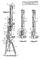
- Figure 1 is a side view of an offshore drill rig platform on which is mounted a folded, telescoped mast of the present invention.
- Figure 2A illustrates an unfolded mast of the present invention with the upper mast section untelescoped outward between its lowest and highest extension.
- Figure 2B is a cut away illustration of the unfolded mast in Figure 2A where the upper mast section is fully extended so that the lower portion of the upper mast is adjacent the transfer frame and the upper portion of the lower mast section.
- Figure 2C is a cut away view of the unfolded mast of 2A where the upper mast section and the transfer frame have moved to a back position to align the upper and lower traveling block guide rails.
- Figure 3 is a cut away view of the dolly rollers secured to the lower portion of the upper mast to guide the upper mast as it extends and retracts relative to the lower mast.
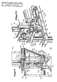
- Figure 4 is a side view, detailed illustration of the transfer frame mounted at the upper end of the lower mast adjacent the lower end of the upper mast.
- Figure 5A is an orthographic view of the back and side of the transfer frame of the present invention adjacent the lower end of the upper mast.
- Figure 5B is an orthographic side view of the front portion of the lower transfer frame member and its connection to the lower mast.
- Figure 6 is a cross section detail view of an upper wheel on the transfer frame, which connects to the upper support member of the lower mast and the drive wheel to move the transfer frame laterally.
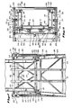
- Figure 7 is a front view of the transfer frame mounted at the upper end of the lower mast as illustrated in Figure 4.
- Figure 8 is a top view of the upper end of the transfer frame taken along lines 8-8 of Figure 2B.
- Figure 9 is a detail illustration of the transfer frame moved to its back position to align the upper and lower masts.
- Figure 10 is a detail illustration of the connection between the upper and lower guide rail for the power swivel.
- Figure 11 is a cross section view of the bolt and plate which connects the upper and lower guide rails illustrated in Figure 10 and taken along lines 11-11 of Figure 10.
- Figure 12 is a detailed illustration of the hydraulic pin assembly which secures the upper mast section to the lower mast section, taken along line 12-12 in Figure 9.
- Figure 13 is a cross section view of a hydraulic pin which secures the upper mast section to the transfer frame, taken along line 13-13 in Figure 5A.
- The present invention enables use of a high rise drill rig mast on limited space drill sites, and particularly on limited space platforms typically used in offshore oil drilling activities. Figure 1 illustrates a side view of a folding
telescoping drill mast 10 of the present invention mounted on a limited areaoffshore platform 12 used to drill wells in the floor of theocean 13. Themast 10 is mounted on thesubstructure 11 of theplatform 12 at pivot points 14 and 16. A skiddingstructure 20 moves on rails and rollers (not illustrated) on themain deck 21 of theplatform 12. - The skidding
structure 20 permits relocating thedrill mast 10 so that a plurality of wells may be drilled at the site. Thevertical lines 23 illustrate various well center lines which may be drilled. The offshore platform includes apipe ramp 24,railing 25 and control andequipment rooms 26. The foldedtelescope drill mast 10 of the present invention includes alower mast 30 which has a lower base orsupport structure 33 and a foldedintermediate section 36. Theintermediate section 36 is cantilevered to thebase structure 33. Thelower mast 30 is U-shaped in cross section and has one open face, which enables anupper mast 39 to nest in theintermediate mast section 36. Ahydraulic jack 42 mounts between thebase section 33 and the foldedintermediate section 36.Hydraulic jack 42 is used to raise foldedintermediate section 36 to the erect position depicted in Figure 2A. During this erection process,leg 99, depicted in Figure 1, rotates about pivot points 14 and 98 to the position shown in Figure 2A. - Figures 2A-C illustrate side views of a folded, telescope-
type mast 10 unfolded and erected on thedrill platform substructure 11. Referring especially to Figure 2A, thebase 33 and theintermediate section 36, after being erected using thehydraulic piston 42, connect at apin 45 and apin 46. Thelower mast section 30 includes a lower powerswivel guide rail 52. The guide rail is a wide flange steel member in which dolly wheels roll against the interior face of the flange. Typically two guide rails are positioned at the back of the mast equidistant laterally from the well centerline. Thelower mast 30 also supports a hydraulic cylinder 54 having a lower guide roller orsheave 56 and an upper guide roller orsheave 58. An upper mast roller orsheave 60 connects to theupper beam 62 of thelower mast section 30. One end of acable sling 64 is secured to abolt 66 on theintermediate mast section 36. Thecable 64 loops over theupper guide roller 58, down and around thelower guide roller 56, up and over theupper mast roller 60 and down to a bolt or tie down 68 on the bottom beam of theupper mast section 39. - Mounted to the upper end of the
lower section 30 is amast support frame 70. Thesupport frame 70 defines a transfer frame which moves theupper mast 39 laterally with respect to thelower mast 30 to a longitudinally aligned drill rig operating position. Theupper mast section 39 includes anupper guide rail 72 for the power swivel. Traveling block pulleys 74 and 76 mount between upwardly extendingflanges shafts upper mast 39.Dolly roller assemblies upper mast section 39 and travel along thelower guide rail 52. - Figure 2B is a cutaway view of the unfolded mast in Figure 2A where the
upper section 39 is fully extended from its telescoped position so that the lower section of theupper mast 39 is adjacent thetransfer frame 70. Thedolly roller assemblies guide rail 87 connected to thetransfer frame 70. Theguide rail dolly wheel assemblies lower guide rail 52 to the transferframe guide rail 87. As illustrated, the lower end of theupper guide rail 72 is adjacent to and offset from the upper end of thelower guide rail 52. Figure 2C however illustrates the extendedupper mast section 39 in a second, back position which places the power swivelupper guide rail 72 and thelower guide rail 52 in alignment. In this second position, thelower mast 30 is pinned to the upper mast. That connection enables transfer of the upper mast loading to the lower mast structural members. - The
transfer frame 70 connects between theupper mast 39 and thelower mast 30. After theupper mast 39 telescopes from thelower mast 30, the lower end of theupper mast 39 rigidly connects to thetransfer frame 70. Thetransfer frame 70, together with theupper mast 39, may then be moved from a first forward position (see Figure 2B) to a second back position (see Figure 2C) to align the upper andlower masts lower guide rails transfer frame 70 are guide roller assemblies (not illustrated) to steady theupper mast 39 as it telescopes in and out of thelower mast 30. Thelower mast 30 also includes roller assemblies (not illustrated) to steady thetransfer frame 70 when it moves between the forward and back positions. Appropriate pin and dog coupling assemblies connect the three structures together rigidly. - To facilitate understanding the structures of the present invention, each of the
lower mast 30, thetransfer frame 70 and theupper mast 39 will be discussed separately with reference to the drawings. Particular emphasis will be placed on the structural members where thelower mast 30, thetransfer frame 70 and theupper mast 39 connect together to permit thetransfer frame 70 and theupper mast 39 to interlock and to move relative to thelower mast 30. Referring to Figures 3-13, elements of thelower mast 30 have identifiers beginning with 200; those of the transfer frame begin with 300; and those for the upper mast elements begin with 400. Considering first thelower mast 30, attention is directed to Figure 8 which is a top view of the telescoping mast of the present invention taken through line 8-8 of Figure 2B. Thelower mast 30 has twoside support members 201 at its top and a connecting backmember 202 which extends between the back ends of theupper support members 201. The front side of the lower mast is open. Afront rail 204 and aback rail 205 extend upwardly from thesupport member 201. Aplate 207 rigidly connects to the upper surface of themember 201. Aflange 208 extends from theplate 207 and ahydraulic cylinder 209 pins to theflange 208. A lateral movementguide roller assembly 211 rigidly connects to the exterior side of themember 201. Theassembly 211 extends up and inwardly and terminates in aroller 213 secured between a pair ofparallel flanges 215. Theflanges 215 rigidly connect to aplate 217 on the side of themember 201. - Turning now to Figure 7, the lower mast section includes a
front leg 219 and anoutside support member 221 which extends upwardly adjacent to thetransfer frame 70. Themember 221 connects to theside member 201. Figure 7 better illustrates how theroller assembly 211 extends up from the side of themember 201 and inwardly towards thetransfer frame 70. Extending across the back of thelower mast 30 is thelower back member 223 as well as various lower mast structural support beams 225. Thelower guide rail 52 extends longitudinally along the interior of the drill mast to thelower back member 223. - Figure 4 is a side view, detailed illustration of the
transfer frame 70 which connects to the upper end of thelower mast 30. Theroller assembly 211 connects throughplate 217 to thesupport beam 201. Theassembly 211 includes theparallel flanges 215 and theroller 213. Also illustrated in Figure 4 is thelower side member 227 which extends between thefront leg 219 and theback leg 229 of thelower mast 30. Extending upwardly from the upper face of themember 227 is afront rail 231 and aback rail 233. Again, thelower guide rail 52 for the power swivel extends up to the upper surface of thelower member 227. Theroller assembly 211 extends over theflange 207 to which is pinned thehydraulic cylinder 209. Ahydraulic pin 237 connects to a flange 239 (not illustrated) mounted between the ends of thelower member 227 and adjacent to the inner end of therail 231. Thehydraulic pin 237 extends through a second flange 241 (not illustrated) on the upper face of themember 227. Thehydraulic pin 237 has a double actuated cylinder which allows the pin to be inserted and removed. - Attention is now directed to the structure of the
transfer frame 70. Thetransfer frame 70 may be considered a substantially rectangular cage-like structure. Turning again to Figure 8, thetransfer frame 70 at its top has afront beam 301, parallel side rails 303 and aback member 305. On the interior side surface of thefront beam 301 is a hydraulic power-drivenpin assembly 307. Thehydraulic pins 307 are double actuated enabling the pin to be inserted and removed. The pins preferably are taper-nosed which allows the pin to wedge through the flange bores and assist alignment of the connection. Theassembly 307 mounts to aflange 311 and includes ahydraulic pin 309. Aparallel flange 313 is spaced apart and is adjacent to theflange 311. Extending upwardly from the upper surface of theback member 305 areparallel flanges 315. Bolted to one of theflanges 315 is a hydraulically actuatedpin 317. Thispin 317 is similar to thepin 309. Four upper-mastguide roller assemblies 319 connect to the upper surface of themember 303. Eachassembly 319 includes a pair ofparallel flanges 321 and aroller 323 disposed between theflanges 321. Twoassemblies 319 are one side of the mast; two are on the laterally opposite side. - Extending through the end of the
front member 301 is ashaft 325 to which is rotatably connected aflanged wheel 327. Theflanged wheel 327 rolls on therail 204. Extending through themember 303 near its back end is ashaft 329. Aflanged wheel 331 mounts to theshaft 329 and theflanged wheel 331 rides on therail 205. The inner flange of thewheel 331 may include as illustrated agear 328. Thegear 328 engages asmaller drive gear 330 connected by adrive shaft 332 to aworm gear reducer 334. Theworm gear 334 engages adrive motor 336. In one embodiment, thedrive motor 336 is hydraulic while in another, the motor is electric. Thedrive shaft 332 is supported bybearings 338 mounted in flanges on the upper face of the back member. Extending outwardly from the exterior of theside member 303 is aflange 333. Pinned to theflange 333 is thepiston 335 of thehydraulic cylinder 209. The hydraulic cylinder thus couples between theflange 333 of the transfer frame and theflange 207 on thelower mast member 201. - Turning now to Figure 7, there is illustrated the power
swivel guide rails 337 on thetransfer frame 70. Therails 337 connect to the interior side of theback member 305. The upper mastguide roller assemblies 319 attach to the upper surfaces of thelower side member 339 and theupper side member 301. In a preferred embodiment, eightguide assemblies 319 are used: four per side with two on theupper member 301; two on thelower member 339. - A better view illustrating the lower
transfer side members 339 is shown in Figure 4. Aside member 341 connects the front end of thelower side member 339 and theupper side member 303. Depending from the lower surface of theside members 339 arewheel assemblies 343. Thewheel assembly 343 includes aflanged wheel 345 which rotates on a pin 347 secured betweenparallel flanges 349. Theflanged wheel 345 rides on therail 231. Awheel assembly 343a depends from the back end of themember 339. The flanged wheel 345a engages and rolls on theback rail 233. - Returning to Figure 8, the
upper mast 39 has two horizontal side beams 401. Aflange 403 having a bore extends from themember 401 and may be engaged by thehydraulic pin 309. On the back side of themember 401 anotherflange 405 extends outwardly. That flange also contains a bore which may be engaged by thehydraulic pin 317. Aback member 407 extends between the back ends of theparallel side members 401. Secured to the inner side face of theback member 407 is theupper guide rail 72. On the laterally opposite face is an uppermast dolly assembly 411. - Figure 7 shows the
legs 413 of the upper mast section. Therollers 323 of the upper mastguide roller assemblies 319 ride on the exterior faces of thelegs 413. Aback support member 415 extends between theparallel legs 413.Appropriate support members 417 connect theback member 415 with alower back member 419.Flanges 421 extend downwardly from thefront legs 413. Theflanges 421 include a bore through which thehydraulic pin 237 may extend. - With the above description of the structural members of the
lower mast 30, thetransfer frame 70, and theupper mast 39, attention is now directed to Figure 5A which is an orthographic view of the back and a side of the transfer frame connections between the three structures discussed above. At the upper end of thelower mast 30 is theside member 201. Attached to the upper surface of themember 201 is theplate 207 and theflange 208 to which is pinned thehydraulic cylinder 209. Thepiston 335 of thecylinder 209 pins to theflange 333 extending from the exterior face of thetransfer side member 303. Theflanged wheel 331 rotatably mounted to theshaft 329 rides on theback rail 205 extending upwardly from the upper face of themember 201.Parallel flanges 321 mount to the upper face of the transferframe side member 303. Pinned between theflanges 321 is theroller 323 which engages the exterior face of thevertical leg 413 of theupper mast 39. Extending from the back face of theleg 413 is theflange 405. Theflange 405 inserts between theparallel flanges 315 on the upper face of theback member 305. Thehydraulic pin 317 bolts to one of theflanges 315. Bores through theflanges hydraulic pin 317 to extend through theflanges transfer frame 70 to theupper mast 39. Figure 5A further provides an illustration of thedolly assembly 411. Thedolly assembly 411 includes aflange 421 which rigidly couples to theback beam 407. Theassembly 411 has a pair ofwheels 423 which are preferably biased outwardly against the flanges of the guide rail in which thedolly 411 is engaged. In this illustration, thewheels 423 press against the flanges of the transferframe guide rail 337. Double wheels reduce the play arising from the difference in the width of the guide rail. - Figure 5B illustrates the connection of the transfer frame and lower mast structures at the front side of the mast. Extending upwardly from the
lower mast member 201 is therail 204. Theflanged wheel 327 rotatably mounted onpin 325 engages therail 204. The transfer frameroller guide assembly 211 mounts with theplate 217 to the exterior face of themember 201.Angled flanges 215 extend up and over the upper face of themember 201 and the upper face of thetransfer member 303. Pinned at the upper end of theflange structure 215 is aroller 213 which engages the upper face of themember 303. Thehydraulic cylinder 209 is pinned at its back end to theflange 208 which connects to thelower mast member 201 by theplate 207. - As noted earlier, Figure 10 is a detailed partial view illustrating the connection between the
upper guide rail 72 and thelower guide rail 52 for the power swivel. Theguide rail 72 has aflange 511 extending perpendicu larly from the back face at the lower end of therail 72. Asimilar flange 513 extends from the back face at the upper end of theguide rail 52. Theflanges bores 515 along the longitudinal axis of the flanges. Aplate 517 having similar bores may be installed on both sides of the flanges. Theplate 517 preferably is U-shaped in cross-section to wedge into theflanges plates 517 and theflanges flanges plate 517 andbolt 519 maintains the guide rails 72 and 52 in alignment and enhances the mast stability. - Figure 9 is a side view of the transfer frame portion of the mast of the present invention after the
upper mast 39 has been fully extended, pinned to thetransfer frame 70 and thetransfer frame 70 moved from a first forward position to a second back position. The movement of thetransfer frame 70 aligns theupper mast 39 with thelower mast 30 and in particular aligns the powerswivel guide rails upper frame 39 may be coupled by thehydraulic pin 237 to thelower mast section 30. This pin coupling enables the upper mast loading to be transferred to the lower mast support structures. Also the guide rails 72 and 52 may be secured together by bolting theplate 517 to theback flanges - Figure 13 provides a detailed illustration of the
hydraulic pin 317 as illustrated in Figure 5A. Thehydraulic cylinder 317 is double acting and hashydraulic tubings parallel flanges 315 which rigidly connect to the upper face of the transfer frame backmember 305. Theflange 405 mounted to the back face of theleg 413 on theupper mast 39 extends between theparallel flanges 315. Apin 505 extends through the bores in theflanges transfer frame 70 with theupper mast 39. - Figure 12 is a detailed illustration taken along line 12-12 of Figure 9 of the
hydraulic pin 237 which couples theupper mast 39 to thelower mast 30. Thepin 237 mounts to anoutside flange 239 extending upwardly from the upper face of themember 227. A second flange 241 extends upwardly adjacent theflange 239.Flanges 421 depend from the lower end of theleg 413. Theflanges hydraulic cylinder 237 extends. Thedouble flanges 239 and 241 provide a stronger connection with theflanges 421 than would a single flange supporting thehydraulic pin 237. Asimilar pin 237 andflange connection - Figure 6 provides a detailed cut away view of an alternate drive for the transfer frame. The
flanged wheel 331 rotatably mounts to ashaft 329 which connects to the transferframe side member 303 adjacent to the transfer frame backmember 305. Theflanged wheel 331 engages theback rail 205 which extends upwardly from the lowermast side member 201. As also illustrated in Figure 5A, thewheel 331 has agear 328 which engages thepinion gear 330. Thegear 330 is driven by theshaft 332. - Figure 3 illustrates the transfer
frame guide rail 337 coupled to the lowermast guide rail 52. The uppermast guide rail 72 is interconnected through thewheel assemblies 411. Aflange 521 extends from the lower end of theguide rail 337 on its back face. The lower end of theflange 521 has a bore which accepts a bolt. Theflange 521 interconnects with theflange 513 of the lowermast guide rail 52 by abolt 519. The lower and theupper dolly assembly 411 are positioned on both sides of theguide rails wheels 423 of theassemblies 411 are preferably biased outwardly against the flanges of the guide rails. Double wheels are gainfully employed to reduce the amount of play in the width of thewide flange members wheel assemblies 411 have a double set of wheels on both sides of the guide rails. - As illustrated in Figure 1, the limited area
offshore platform 12 having a limited amount of area on which to install a crane, housing and offices, a drill mast, and other drill rig items used to drill wells in the floor of theocean 13 is floated to the drill site. The foldeddrill mast 10 of the present invention may be mounted to the sub-structure 11 before theplatform 12 moves to the ocean site. The platform with the folded telescoped mast is stable while floating to the drill site because the compact folded mast of the present invention has a low center of gravity. In the alternative, the platform may first be floated to the drill site and anchored to the sea bottom. The mast may then be barged to the site and hoisted to thesubstructure 11 by a crane. Themast 10 is pivotally connected to thesubstructure 11. The pivot points 14 and 16 permit thelower section 33 and the intermediate section of thelower mast 30 to elevate into an erect position. In this regard, there are various methods which may be used to elevate or lower folded masts; the illustrated embodiment in Figure 1 uses ahydraulic jack 42 coupled between thelower base section 33 and theintermediate section 36 to unfold thelower mast 30. After the lower mast is erected, thebase 33 andintermediate section 36 are rigidly connected at thepin 45 and thepin 46. - The
upper mast 39 may then be erected. Theupper mast 39 cradles in the U-shaped lower mast, and connects to thelower guide rail 52 bydolly assemblies cable sling 64 is secured to thebolt 66 on theintermediate mast section 36. Thecable 64 cooperates with the hydraulic cylinder 54 supported in thelower mast 30 to extend the upper mast (or retract it if the mast is being disassembled). Thecable 64 loops over theupper guide roller 58 which is connected to the piston of the hydraulic cylinder 54. Thecable 64 then loops downward under thelower guide roller 56 at the fixed end of the hydraulic cylinder 54. Thecable 64 threads up and over theupper mast roller 60 connected at theupper end 62 of thelower mast 30. Thecable 64 finally secures to abolt 68 on the bottom beam of theupper mast section 39 below thedolly assembly 86. - Activation of the hydraulic cylinder 54 extends the piston from the cylinder 54. The
line 64 being elevated by thepiston roller 58 pulls theupper mast 39 upward. As illustrated in Figures 2A and 3, thedolly assemblies lower guide rail 52 to guide and to stabilize theupper mast 39. Figures 5A and 7 show that the uppermast guide rollers 323 connected by theflange 321 to the upper face of the transferframe side members 303 also guide and steady theupper mast 39 as it telescopes from thelower mast 30. As best illustrated in Figure 7, the eightguide rollers 323 roll on the exterior face of theupper mast legs 413. - Once the
upper mast 39 is in its fully extended position as illustrated in Figure 2B, the upper mast is pinned to thetransfer frame 70. Thehydraulic pin assemblies flanges transfer frame 70. Thedolly rollers guide rail 52 move on theguide rail 337 of thetransfer frame 70. Theguide rail 337 is similar to theupper guide rail 72 and thelower guide rail 52. As illustrated in Figure 3, theguide rail 337 is bolted to thelower guide rail 52 prior to extending the upper mast. Abolt 519 connects theflanges guide rails - After the upper mast is fully extended, the upper mast is pinned to the transfer frame as explained above. The transfer
frame guide rail 337 illustrated in Figure 3 is disconnected from theflange 513 of thelower guide rail 52 by removing thebolt 519. - The
transfer frame 70 is then ready to move with theupper mast 39 from the forward position to a back position. The lateral movement with respect to thelower mast 30 longitudinally aligns therail 72 with thelower guide rail 52. Such alignment also positions thesupport legs - Figure 8 illustrates two different systems to move the
transfer frame 70 from its forward position to the back position. One involves use of thehydraulic piston 209 connected by theflange 208 to the upper face of thelower mast member 201. Thepiston 335 of thehydraulic cylinder 209 pins to aflange 333 projecting from the side face of thetransfer frame member 303. Activation of thehydraulic cylinder 209 pushes against theflange 333 and moves the transfer frame rearward. Theflanged wheels transfer frame member 303 roll onrails flange wheel assemblies 343 depending from the lowertransfer frame member 339 roll onrails - As illustrated in Figure 5B, the transfer frame
guide roller assembly 211 stabilizes thetransfer frame 70 as thetransfer frame 70 with the extendedupper mast 39 moves from one position to the other. Theroller 213 of theassembly 211 rolls on the upper face of thetransfer frame member 303. - Figure 8 also provides a top view of a second system to move the
transfer frame 70. Theflanged wheel 331 connects on its inner face to agear 328. Thegear 328 engages adrive gear 330 which connects by adrive shaft 332 through aworm gear reducer 334 to adrive motor 336. Thevarious wheel assemblies rails hydraulic cylinder 209 to push and pull thetransfer frame 70 between positions. - Once the transfer frame is moved to the back position as illustrated in Figure 2C, the
upper mast 39 is pinned to thelower mast 30. Thehydraulic cylinder 237 pushes a pin through theflange 239 connected to the upper face of themember 227. The pin extends to theflanges 421 which depend from theleg 413 of theupper mast 39. Securely pinning theupper mast 39 to thelower mast 30 enables transferring the upper mast load to the support structure of thelower mast 30. - Finally, the
upper guide rail 72 and thelower guide rail 52 are securely bolted together. As illustrated in Figures 10 and 11,plates 517 are placed on both sides over the adjoiningflanges rails Appropriate bolts 519 extend through thebores 515 and rigidly connect theflanges - Thus, the present invention provides a folded telescoped drill mast which employs power swivel technology to drive the drill string, without sacrificing the cost effective derrick heights typically used on offshore drilling platforms. These mast heights on typical rigs reach heights of 160 or more feet which is sufficient for three lengths of drill pipe between the drill floor of the
substructure 11 and the power swivel. Alower rail 52 guides and helps stabilize theupper mast 39 as it telescopes in or out of thelower mast 30. Once theupper mast 39 is fully erected, theupper mast 39 is pinned to thetransfer frame 70 which moves theupper mast 39 laterally to align anupper guide rail 72 with thelower rail 52. When such alignment occurs, the structural support legs of theupper mast 39 and thelower mast 30 cooperate to support the structural load on the mast during drilling operations. - To lower the mast, the process is reversed. The
upper rail 72 is disconnected from thelower rail 52 by removing thebolts 519 which secure theplates 517 to the adjoiningflanges upper mast 39 from thelower mast 30. The transfer frame moves from its back position to the forward position. In one embodiment, the transfer frame is moved by retracting thehydraulic cylinder 209. In another embodiment, themotor 336 turns thedrive shaft 332 which drivespinion 330 against thegear 328. In both embodiments, thewheels rails frame guide rail 337 with thelower guide rail 52. As illustrated in Figure 3, theupper guide rail 337 may be rigidly connected to theflange 513 of thelower guide rail 52. - With the
guide rail 337 bolted to thelower guide rail 52, theupper mast 39 is released from its connections with thetransfer frame 70. The pins in thehydraulic pin assemblies flanges cable 64 weaved throughrollers bolt 66 and to the upper mast by abolt 68 cooperates with the cylinder 54 to retract theupper mast 39 into thelower mast 30. - With the
upper mast 39 fully retracted into thelower mast 30, pins 45 and 46 are removed. Thehydraulic cylinder 42 then operates to unfold or collapse thelower section 33 around a pivot point to fold theintermediate section 36 over thelower section 33. The mast may then be disconnected from the substructure, lifted by a crane to a barge, and transported to another drill platform. - The principles, preferred embodiments and modes of operation of the present invention have been described in the foregoing specification. The invention is not to be construed as limited to the particular forms disclosed, since these are regarded as illustrative rather than restrictive. Moreover, variations and changes may be made by those skilled in the art without departing from the spirit of the invention as described by the following claims.
Claims (17)
1. A folding, telescoping drill rig mast, comprising:
a base structure;
a lower mast including a lower support section pivotally connected to the base structure and an intermediate section cantilevered to the lower support section and rotatable from a first horizontal position to a second vertical position;
a guide rail extending longitudinally through the intermediate mast section;
an upper mast slideably nested within the intermediate mast section;
a dolly mounted on the upper mast to engage the lower guide rail to guide the upper mast from a first position within the lower mast to a second position extending beyond the free end of the lower mast; and
a transfer frame at the free end of the lower mast, in which the upper mast is secured, and movable laterally relative to the lower mast between a first position with the upper guide rail offset from the lower guide rail to a second position with the upper guide rail in longitudinal alignment with the lower guide rail.
2. A folding, telescoping drill rig mast as recited in claim 1, further comprising:
a pair of horizontally disposed rails at the free end of the intermediate mast section, and
a wheel with flanges to roll on each rail for rolling the transfer frame from the first position to the second position.
a pair of horizontally disposed rails at the free end of the intermediate mast section, and
a wheel with flanges to roll on each rail for rolling the transfer frame from the first position to the second position.
3. A folding, telescoping drill rig mast as recited in claim 1, wherein the guide rail has a flange.
4. A folding, telescoping drill rig mast as recited in claim 3, wherein the dolly further comprises:
a pair of flanges extending from the back of the upper mast; and
at least one wheel rotatably mounted on a shaft between the flanges, the wheel to engage the guide rail.
a pair of flanges extending from the back of the upper mast; and
at least one wheel rotatably mounted on a shaft between the flanges, the wheel to engage the guide rail.
5. A folding, telescoping drill rig mast as recited in claim 4, wherein the wheel is biased against a flange of the guide rail.
6. A folding, telescoping drill rig mast as recited in claim 4, wherein the dolly has two wheels.
7. A folding, telescoping drill rig mast as recited in claim 6, wherein the wheels are oppositely biased against flanges.
8. A folding, telescoping drill rig mast as recited in claim 3, wherein the dolly has at least one wheel on each side of the flanged guide rail.
9. A folding, telescoping drill rig mast as recited in claim 1, further comprising means to guide the transfer frame as it moves between the first and second position.
10. A folding, telescoping drill rig mast as recited in claim 9, wherein the guide means comprises:
a flange member connected to the free end of the lower mast extending upward and inwardly towards the transfer frame; and
a roller rotatably mounted on a shaft connected to the flange member, the wheel to engage the transfer frame.
a flange member connected to the free end of the lower mast extending upward and inwardly towards the transfer frame; and
a roller rotatably mounted on a shaft connected to the flange member, the wheel to engage the transfer frame.
11. A folding, telescoping drill rig mast as recited in claim 1, further comprising means to steady and guide the upper mast as it extends or retracts from the lower mast.
12. A folding, telescoping drill rig mast as recited in claim 11, wherein the guide means comprises:
a pair of flanges connected to the transfer frame; and
a roller rotatably mounted on a shaft between the flanges, the wheel to engage the upper mast.
a pair of flanges connected to the transfer frame; and
a roller rotatably mounted on a shaft between the flanges, the wheel to engage the upper mast.
13. A folding, telescoping drill rig mast as recited in claim 1, further comprising a power swivel mounted on the guide rail.
14 A foldable, telescoping drill rig comprising:
a base;
a first mast section pivotally mounted at a first end to the base and adapted to pivot between a laterally disposed folded position and a vertically disposed, unfolded position;
a second mast section pivotally mounted at a first end to the second end of the first mast section and adapted to pivot between a folded position along side the first mast section and an unfolded position extending from the second end of the first mast section in longitudinal alignment with the first mast section;
a third mast section mounted within the second mast section in longitudinally telescoping relation and adapted to move between a retracted position within the second mast section and an extended position projecting from the second end of second mast section; and
a mast support member mounted at the upper end of the second mast section in laterally movable relation with the second mast member and configured to support the third mast section from the second mast section, said mast support member adapted to be moved laterally with the third mast section relative to the second mast section between a first position in which the third mast section is in longitudinal alignment with the second mast section and a second position in which the second and third mast sections are parallel but offset.
15. The drilling rig of claim 14, further comprising:
a power swivel mounted within one of the mast sections when the mast sections are folded and retracted and movable longitudinally within all three sections when the three mast sections are unfolded and projected and in longitudinal alignment.
a power swivel mounted within one of the mast sections when the mast sections are folded and retracted and movable longitudinally within all three sections when the three mast sections are unfolded and projected and in longitudinal alignment.
16. A foldable, telescoping drill rig, comprising:
a base;
a first mast section pivoted at a first end to the base to swing around such pivot between a folded, laterally disposed position and an unfolded, vertically disposed position;
a second mast section pivoted at a first end to the second end of the first mast section to swing around the second end of the first mast section between a folded position alongside the first mast and an unfolded position extending from the second end of the first mast section in longitudinal alignment;
a third mast section adapted to fit within the second mast section in longitudinally telescoping relation between a retracted position in the second mast section and an extended position projecting beyond the second end of the second mast section;
a separate set of guide rails in each mast section configured to transport a power swivel along the each said section, the sets of guide rails in the first and second mast sections positioned to be in automatic alignment when these two mast sections are unfolded and vertically disposed;
the set of guide rails in the third mast section being alignable with the set of guide rails in the second mast section when the third mast section is in its extended position.
17. The drilling rig of claim 16 including a power swivel mounted on a set of said guide rails.
Applications Claiming Priority (2)
| Application Number | Priority Date | Filing Date | Title |
|---|---|---|---|
| US108195 | 1987-10-13 | ||
| US07/108,195 US4837992A (en) | 1987-10-13 | 1987-10-13 | Folded/telescoped drill rig mast for limited space platform |
Publications (2)
| Publication Number | Publication Date |
|---|---|
| EP0312286A2 true EP0312286A2 (en) | 1989-04-19 |
| EP0312286A3 EP0312286A3 (en) | 1990-10-31 |
Family
ID=22320815
Family Applications (1)
| Application Number | Title | Priority Date | Filing Date |
|---|---|---|---|
| EP19880309475 Withdrawn EP0312286A3 (en) | 1987-10-13 | 1988-10-11 | Folded/telescoped drill rig mast for limited space platform |
Country Status (2)
| Country | Link |
|---|---|
| US (1) | US4837992A (en) |
| EP (1) | EP0312286A3 (en) |
Cited By (6)
| Publication number | Priority date | Publication date | Assignee | Title |
|---|---|---|---|---|
| ES2048622A1 (en) * | 1991-07-12 | 1994-03-16 | Alquezar Gazulla | Tower for the extraction of liquids by drilling. |
| WO1994023173A1 (en) * | 1993-04-02 | 1994-10-13 | Continental Emsco Company | Vertically erected mast |
| WO2009097574A2 (en) * | 2008-01-30 | 2009-08-06 | Process Manufacturing Corp. | Small footprint drilling rig |
| KR101313204B1 (en) | 2012-05-08 | 2013-09-30 | 삼성중공업 주식회사 | Jack-up platform |
| CN104295241A (en) * | 2014-10-24 | 2015-01-21 | 浙江乔兴建设集团有限公司 | Using-conveniently punching frame |
| US10633931B1 (en) | 2009-09-25 | 2020-04-28 | Swivel Rental & Supply, L.L.C. | Support apparatus for supporting down hole rotary tools |
Families Citing this family (47)
| Publication number | Priority date | Publication date | Assignee | Title |
|---|---|---|---|---|
| NL1006373C2 (en) * | 1997-06-20 | 1999-01-05 | Kema Nv | Method for erecting an emergency high-voltage pylon and design and collection of parts therefor. |
| CA2413825C (en) * | 2002-12-10 | 2007-07-17 | Allan R. Nelson Engineering (1997) Inc. | Telescoping rig with torque carrier |
| US7138038B1 (en) * | 2004-02-23 | 2006-11-21 | James N Britton | Expandable anode pod |
| US20100277584A1 (en) * | 2007-02-12 | 2010-11-04 | Price Larry J | Systems and Methods for Video Surveillance |
| CN100510308C (en) * | 2007-06-15 | 2009-07-08 | 张宝有 | Well drilling top drive guide rail plate |
| US8128332B2 (en) | 2007-10-24 | 2012-03-06 | T & T Engineering Services, Inc. | Header structure for a pipe handling apparatus |
| US7918636B1 (en) * | 2007-10-24 | 2011-04-05 | T&T Engineering Services | Pipe handling apparatus and method |
| US8469648B2 (en) | 2007-10-24 | 2013-06-25 | T&T Engineering Services | Apparatus and method for pre-loading of a main rotating structural member |
| US8419335B1 (en) | 2007-10-24 | 2013-04-16 | T&T Engineering Services, Inc. | Pipe handling apparatus with stab frame stiffening |
| US20090200856A1 (en) * | 2008-02-13 | 2009-08-13 | Chehade Elie J | Methods and systems for raising and lowering a rig mast and substructure by remote control |
| US8468753B2 (en) * | 2008-02-29 | 2013-06-25 | National Oilwell Varco L.P. | Drilling rigs and erection methods |
| US8813436B2 (en) | 2008-02-29 | 2014-08-26 | National Oilwell Varco, L.P. | Pinned structural connection using a pin and plug arrangement |
| US8047303B2 (en) * | 2008-02-29 | 2011-11-01 | National Oilwell Varco L.P. | Drilling rig drawworks installation |
| US8250816B2 (en) * | 2008-02-29 | 2012-08-28 | National Oilwell Varco L.P. | Drilling rig structure installation and methods |
| US8549815B2 (en) * | 2008-02-29 | 2013-10-08 | National Oilwell Varco L.P. | Drilling rig masts and methods of assembly and erecting masts |
| US8550174B1 (en) | 2008-12-22 | 2013-10-08 | T&T Engineering Services, Inc. | Stabbing apparatus for centering tubulars and casings for connection at a wellhead |
| US8256520B2 (en) * | 2009-01-14 | 2012-09-04 | National Oilwell Varco L.P. | Drill ship |
| US8192128B2 (en) | 2009-05-20 | 2012-06-05 | T&T Engineering Services, Inc. | Alignment apparatus and method for a boom of a pipe handling system |
| US9556689B2 (en) | 2009-05-20 | 2017-01-31 | Schlumberger Technology Corporation | Alignment apparatus and method for a boom of a pipe handling system |
| KR101137400B1 (en) * | 2009-10-20 | 2012-04-20 | 대우조선해양 주식회사 | Foldable derrick structure for a ship |
| MX336428B (en) | 2010-12-30 | 2016-01-18 | T & T Engineering Services Inc | Fast transportable drilling rig system. |
| US20120291684A1 (en) * | 2011-05-19 | 2012-11-22 | Gavin Humphreys | Ice Breaking Drilling Vessel With Stowable Mast |
| AU2012262632B2 (en) * | 2011-06-02 | 2016-07-28 | National Oilwell Varco, L.P. | Drilling rig system with self-elevating drill floor |
| US9091128B1 (en) | 2011-11-18 | 2015-07-28 | T&T Engineering Services, Inc. | Drill floor mountable automated pipe racking system |
| US9091125B2 (en) | 2012-01-16 | 2015-07-28 | National Oilwell Varco, L.P. | Collapsible substructure for a mobile drilling rig |
| US9708860B2 (en) * | 2012-06-21 | 2017-07-18 | Superior Energy Services-North America Services, Inc | Ground level rig and method |
| US9926719B2 (en) | 2013-02-13 | 2018-03-27 | Nabors Drilling Technologies Usa, Inc. | Slingshot side saddle substructure |
| US9476267B2 (en) | 2013-03-15 | 2016-10-25 | T&T Engineering Services, Inc. | System and method for raising and lowering a drill floor mountable automated pipe racking system |
| WO2014182991A1 (en) | 2013-05-10 | 2014-11-13 | Devin International, Inc. | Drilling rig transfer system and method |
| US20150197993A1 (en) * | 2014-01-15 | 2015-07-16 | Eunkwang Industrial Co.,Ltd. | Derrick lift system of offshore structure |
| EA036726B1 (en) * | 2014-07-14 | 2020-12-11 | Дреко Энерджи Сервисез Юлс | Mobile drilling rig |
| US10196860B2 (en) | 2014-09-17 | 2019-02-05 | David C. Wright | Telescopic mini-rig |
| RU2577564C1 (en) * | 2014-12-25 | 2016-03-20 | Ооо Нпц "Металлург" | Mechanism of movement and alignment for cluster rig construction of wells |
| US9650840B2 (en) | 2015-04-27 | 2017-05-16 | National Oilwell Varco, L.P. | Method and apparatus for erecting a drilling rig |
| US9988807B2 (en) | 2016-02-24 | 2018-06-05 | National Oilwell Varco, L.P. | Drilling rig with self-elevating drill floor |
| US10822924B2 (en) | 2016-03-07 | 2020-11-03 | National Oilwell Varco, L.P. | Multi-well bop cellar trailer |
| US9970211B2 (en) * | 2016-05-02 | 2018-05-15 | Dreco Energy Services Ulc | Guide rails for mobile drilling rig |
| US10214936B2 (en) | 2016-06-07 | 2019-02-26 | Nabors Drilling Technologies Usa, Inc. | Side saddle slingshot drilling rig |
| US10648240B2 (en) | 2016-07-13 | 2020-05-12 | Nabors Drilling Technologies Usa, Inc. | Mast and substructure |
| US10584541B2 (en) * | 2016-07-28 | 2020-03-10 | Nabors Drilling Technologies Usa, Inc. | Pipe handling apparatus |
| US10293854B2 (en) | 2016-10-05 | 2019-05-21 | Dreco Energy Services Ulc | Movable rig and steering system |
| US10704337B2 (en) | 2016-11-07 | 2020-07-07 | Nabors Drilling Technologies Usa, Inc. | Side-saddle cantilever mast |
| US10815735B1 (en) | 2017-02-23 | 2020-10-27 | Swivel Rental & Supply, L.L.C. | Swivel stand apparatus and associated equipment |
| US10837238B2 (en) | 2018-07-19 | 2020-11-17 | Nabors Drilling Technologies Usa, Inc. | Side saddle slingshot continuous motion rig |
| WO2020028969A1 (en) | 2018-08-06 | 2020-02-13 | Dreco Energy Services Ulc | Drill floor support structures |
| US11603723B2 (en) | 2019-08-30 | 2023-03-14 | Nov Canada Ulc | Cuttings processing unit |
| WO2022051192A1 (en) | 2020-09-01 | 2022-03-10 | Nabors Drilling Technologies Usa, Inc. | Side saddle traversable drilling rig |
Citations (8)
| Publication number | Priority date | Publication date | Assignee | Title |
|---|---|---|---|---|
| US2336432A (en) * | 1941-05-24 | 1943-12-07 | Wilson John Hart | Oil well servicing mast |
| US2804948A (en) * | 1953-09-25 | 1957-09-03 | Moore Corp Lee C | Telescoping portable mast |
| US2804949A (en) * | 1954-03-16 | 1957-09-03 | Moore Corp Lee C | Telescoping portable mast |
| US3295270A (en) * | 1964-11-05 | 1967-01-03 | Moore Corp Lee C | Folded oil well mast structure |
| US3949818A (en) * | 1974-09-30 | 1976-04-13 | Western Gear Corporation | Hydraulic drilling rig and power swivel |
| US4134237A (en) * | 1976-08-02 | 1979-01-16 | Pool Company | Modular section mast |
| GB2081342A (en) * | 1980-08-04 | 1982-02-17 | Patterson Bradley Craig | Support means to transport a drawworks and drilling mast and forming support means at a drilling location |
| US4393630A (en) * | 1981-03-12 | 1983-07-19 | Crane Carrier Corporation | Actuation means for the racking platform of a mast |
Family Cites Families (1)
| Publication number | Priority date | Publication date | Assignee | Title |
|---|---|---|---|---|
| US4371046A (en) * | 1980-04-21 | 1983-02-01 | Vernon Read | Apparatus for and method of drilling a hole into the ground |
-
1987
- 1987-10-13 US US07/108,195 patent/US4837992A/en not_active Expired - Fee Related
-
1988
- 1988-10-11 EP EP19880309475 patent/EP0312286A3/en not_active Withdrawn
Patent Citations (8)
| Publication number | Priority date | Publication date | Assignee | Title |
|---|---|---|---|---|
| US2336432A (en) * | 1941-05-24 | 1943-12-07 | Wilson John Hart | Oil well servicing mast |
| US2804948A (en) * | 1953-09-25 | 1957-09-03 | Moore Corp Lee C | Telescoping portable mast |
| US2804949A (en) * | 1954-03-16 | 1957-09-03 | Moore Corp Lee C | Telescoping portable mast |
| US3295270A (en) * | 1964-11-05 | 1967-01-03 | Moore Corp Lee C | Folded oil well mast structure |
| US3949818A (en) * | 1974-09-30 | 1976-04-13 | Western Gear Corporation | Hydraulic drilling rig and power swivel |
| US4134237A (en) * | 1976-08-02 | 1979-01-16 | Pool Company | Modular section mast |
| GB2081342A (en) * | 1980-08-04 | 1982-02-17 | Patterson Bradley Craig | Support means to transport a drawworks and drilling mast and forming support means at a drilling location |
| US4393630A (en) * | 1981-03-12 | 1983-07-19 | Crane Carrier Corporation | Actuation means for the racking platform of a mast |
Cited By (10)
| Publication number | Priority date | Publication date | Assignee | Title |
|---|---|---|---|---|
| ES2048622A1 (en) * | 1991-07-12 | 1994-03-16 | Alquezar Gazulla | Tower for the extraction of liquids by drilling. |
| WO1994023173A1 (en) * | 1993-04-02 | 1994-10-13 | Continental Emsco Company | Vertically erected mast |
| US5423158A (en) * | 1993-04-02 | 1995-06-13 | Continental Emsco Company | Vertically erected mast |
| WO2009097574A2 (en) * | 2008-01-30 | 2009-08-06 | Process Manufacturing Corp. | Small footprint drilling rig |
| WO2009097574A3 (en) * | 2008-01-30 | 2009-10-29 | Process Manufacturing Corp. | Small footprint drilling rig |
| US7931076B2 (en) | 2008-01-30 | 2011-04-26 | Process Manufacturing Corp. | Small footprint drilling rig |
| US10633931B1 (en) | 2009-09-25 | 2020-04-28 | Swivel Rental & Supply, L.L.C. | Support apparatus for supporting down hole rotary tools |
| KR101313204B1 (en) | 2012-05-08 | 2013-09-30 | 삼성중공업 주식회사 | Jack-up platform |
| CN104295241A (en) * | 2014-10-24 | 2015-01-21 | 浙江乔兴建设集团有限公司 | Using-conveniently punching frame |
| CN104295241B (en) * | 2014-10-24 | 2017-02-15 | 浙江乔兴建设集团有限公司 | Using-conveniently punching frame |
Also Published As
| Publication number | Publication date |
|---|---|
| US4837992A (en) | 1989-06-13 |
| EP0312286A3 (en) | 1990-10-31 |
Similar Documents
| Publication | Publication Date | Title |
|---|---|---|
| US4837992A (en) | Folded/telescoped drill rig mast for limited space platform | |
| RU2564297C2 (en) | Quickly transported drilling rig | |
| US9488013B2 (en) | Bi-directionally raisable drilling rig mast | |
| US9169698B2 (en) | Modular drilling rig system | |
| US6634436B1 (en) | Mobile land drilling apparatus and method | |
| US8863449B2 (en) | Substructure of a mobile drilling rig with a movable center floor section | |
| US4021978A (en) | Mast assembly | |
| US4290495A (en) | Portable workover rig with extendable mast substructure, platform mounted drawworks and adjustable wellhead anchor | |
| US20180230709A1 (en) | Modular drilling rig system and method for assembling the same | |
| US8549815B2 (en) | Drilling rig masts and methods of assembly and erecting masts | |
| US3942593A (en) | Drill rig apparatus | |
| US7306055B2 (en) | Automatic method for installing mobile drilling rig at a drilling site | |
| CA2572663C (en) | Automated system for positioning and supporting the work platform of a mobile workover and well-servicing rig | |
| RU2483186C2 (en) | Method for facilitating drilling plant installation | |
| US8006751B2 (en) | Automated system for positioning and supporting the work platform of a mobile workover and well-servicing rig | |
| US7413393B1 (en) | Method for loading and unloading substructures for a mobile drilling rig | |
| CA2703803A1 (en) | Land rig | |
| MXPA05011502A (en) | Fast moving drilling rig. | |
| WO1994023173A1 (en) | Vertically erected mast | |
| CA2982786C (en) | Catwalk system and method | |
| AU2009225260A1 (en) | Collapsible drilling rig |
Legal Events
| Date | Code | Title | Description |
|---|---|---|---|
| PUAI | Public reference made under article 153(3) epc to a published international application that has entered the european phase |
Free format text: ORIGINAL CODE: 0009012 |
|
| AK | Designated contracting states |
Kind code of ref document: A2 Designated state(s): AT BE CH DE ES FR GB GR IT LI LU NL SE |
|
| PUAL | Search report despatched |
Free format text: ORIGINAL CODE: 0009013 |
|
| AK | Designated contracting states |
Kind code of ref document: A3 Designated state(s): AT BE CH DE ES FR GB GR IT LI LU NL SE |
|
| 17P | Request for examination filed |
Effective date: 19910426 |
|
| STAA | Information on the status of an ep patent application or granted ep patent |
Free format text: STATUS: THE APPLICATION IS DEEMED TO BE WITHDRAWN |
|
| 18D | Application deemed to be withdrawn |
Effective date: 19920501 |