EP0176079A2 - Verfahren und Vorrichtung für Probenaufgabe mit und ohne Abzweigung in Kapillarsäulen mittels einer Injektionsspritze - Google Patents
Verfahren und Vorrichtung für Probenaufgabe mit und ohne Abzweigung in Kapillarsäulen mittels einer Injektionsspritze Download PDFInfo
- Publication number
- EP0176079A2 EP0176079A2 EP85112102A EP85112102A EP0176079A2 EP 0176079 A2 EP0176079 A2 EP 0176079A2 EP 85112102 A EP85112102 A EP 85112102A EP 85112102 A EP85112102 A EP 85112102A EP 0176079 A2 EP0176079 A2 EP 0176079A2
- Authority
- EP
- European Patent Office
- Prior art keywords
- split
- sample
- syringe
- column
- needle
- Prior art date
- Legal status (The legal status is an assumption and is not a legal conclusion. Google has not performed a legal analysis and makes no representation as to the accuracy of the status listed.)
- Granted
Links
Images

Classifications
-
- G—PHYSICS
- G01—MEASURING; TESTING
- G01N—INVESTIGATING OR ANALYSING MATERIALS BY DETERMINING THEIR CHEMICAL OR PHYSICAL PROPERTIES
- G01N30/00—Investigating or analysing materials by separation into components using adsorption, absorption or similar phenomena or using ion-exchange, e.g. chromatography or field flow fractionation
- G01N30/02—Column chromatography
- G01N30/04—Preparation or injection of sample to be analysed
- G01N30/16—Injection
- G01N30/18—Injection using a septum or microsyringe
-
- G—PHYSICS
- G01—MEASURING; TESTING
- G01N—INVESTIGATING OR ANALYSING MATERIALS BY DETERMINING THEIR CHEMICAL OR PHYSICAL PROPERTIES
- G01N30/00—Investigating or analysing materials by separation into components using adsorption, absorption or similar phenomena or using ion-exchange, e.g. chromatography or field flow fractionation
- G01N30/02—Column chromatography
- G01N30/04—Preparation or injection of sample to be analysed
- G01N30/06—Preparation
- G01N30/10—Preparation using a splitter
Definitions
- the invention concerns a device for the split- and splitless sampling (with external vaporization) onto capillary columns by syringe with the aim of improved precision and accuracy of quantitative analysis.
- split sampling is the simplest technique for regulating the sample amount that is to enter capillary columns in order to avoid overloading.
- the sampling volume or the sample amount which is actually entering the column can be varied in a double manner, either by the volume which is adjusted within the syringe cylinder or, over a wider range by the splitting ratio, i. e., the ratio between the splitting-flow of the carrier gas leaving the system, and that smaller part of the carrier-gas-flow that enters the column.
- Splitting ratios are usually varied within the range of 1:10 - 1:500.
- the procedure of split sampling can be described as follows: The sample volume is adjusted within a common syringe of 1-10 -1 total volume; about 0.1-1.0 -1 are dosed. The syringe needle is then introduced via the septum into the hot vaporization chamber of the injector. The sample is extruded from the syringe into the vaporization chamber by piston moving. The sample is vaporized and homogeneously mixed with the carrier gas. Thereby droplet (aerosol) formation is prevented by a packing of deactivated glass or quartz wool. The vaporization temperature within the insert (200 - 300 °C) must be adjusted according to the volatility of the less volatile sample constituents.
- the mixture of carrier gas-sample vapour is quickly transferred from the vaporization part of the insert into its split region by the high carrier-gas-flow, there, where the splitting takes place, according to the splitting ratio (ratio of splitting flow to column flow of carrier gas).
- the splitting ratio ratio of splitting flow to column flow of carrier gas
- the column itself (but not the column inlet which protrudes into the heated vaporization chamber) can be maintained at temperatures which are usually lower than the injector temperatur is during the sample transfer into the column.
- the column temperatures may also be low, if temperature programming is to be applied for the separation.
- the injector temperature must be high, if components of low volatility are, however, contained within the sample.
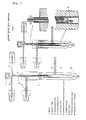
- Fig. 1 and 2 sketcheses of the construction proposed and schemes of operation of this new type of device with which the split sampling errors are being avoided, as discussed above, are shown in Fig. 1 and 2:
- the needle of the syringe is so far moved through the septum 1 and through the tube 6 that the needle tip only just protrudes from the lower end of the cooling mantle into the vaporization chamber.
- the cooling medium enters the device through 3 which leaves the lower end of the tube 3 and then flows upwards along the cooling mantle 4.
- the cooling medium leaves the cooling device at 4 in Fig.
- the tube 4 is closed at the lower end, preventing that the cooling medium enters the vaporization chamber 9.
- a temporary (short time) but, if desired, also a permanent cooling of the whole needle can be attained during the period of the needle introduction as long as the needle is kept within the injector.
- the needle cooling which concerns this invention, is also suited to reduce the discrimination and other sampling errors arising from the wide volatility range of the sample with the known splitless sampling method.
- the cooled needle split or splitless sampling can also be successfully applied to aqueous samples.
- the temperature programmed operation of the whole injector (PTV), as described above, is inferior to the invention concerned CNS technique, mainly, because of the more sophisticated construction and because of the splitting errors which cannot completely suppressed with the PTV-technique cuased by changes of the splitting ratio during the heating period. Discrimination of the more volatile components cannot be avoided.
- the decisive conclusion promoting ,the advantages of the invention concerned technique, in contrary to others, can be made on the basis of comparing the data of the measurement series 4 and 5 (CNS) in Table 1 with the data of series 7 and 9 (cold "on-column" injection) in Table 2.
- a standard split injector with a glasswool packed insert was used in a Varian 3700 GC with PID. The same injector was also used for the series 2-5.
- the temperature of the splitter was 260 °C, the splitting ratio 1:44.
- the selective vaporization from the needle deteriorates the quantitative data, if the injection is performed too slowly, if the splitter temperature is too high, if the solvent is too volatile, and if the carrier gas is hydrogen, etc. (G. Schomburg, H. Husmann, R.Rittmann, J. Chromatogr. 204 (1981) 85). Strong discrimination of the high C-number paraffins is observed because of selective vaporization of the volatile hydrocarbons.
- the additional device which is in conformity with the invention that allows to keep the syringe needle cold during the dosing procedure, was primarily tested without a flow of the ' cooling medium. As with Series 1 much too high areas were found for the less volatile paraffins. The splitting ratio in this series was 1:60.
- the device and the paramters of operation were not changed, but the needle cooling was carried out with cold C0 2 originating from the head space of a C0 2 cylinder.
- the "on-column" injection was executed by using an SGE device originating from the SGE company (D-6108, Rothstadt, GFR). Similar data like with the CNS technique were obtained. The relative standard deviations were below 1 % in average.
- the "on-column" injection was executed using a device originating from the Carlo Erba Company, Milano, Italy. This injector was equipped with the so-called secondary cooling, at which the column inlet can be cooled additionally.
- the data obtained are in good agreement with the CNS data obtained in Series 4 and 5 of Table 1 and prove that samples ranging widely in component volatilities can be introduced into hot splitters without considerable discrimination. Moreover the peak areas obtained (column loads) are directly proportional to the splitting ratio.
Landscapes
- Physics & Mathematics (AREA)
- Health & Medical Sciences (AREA)
- Life Sciences & Earth Sciences (AREA)
- Chemical & Material Sciences (AREA)
- Analytical Chemistry (AREA)
- Biochemistry (AREA)
- General Health & Medical Sciences (AREA)
- General Physics & Mathematics (AREA)
- Immunology (AREA)
- Pathology (AREA)
- Sampling And Sample Adjustment (AREA)
- Treatment Of Liquids With Adsorbents In General (AREA)
Priority Applications (1)
| Application Number | Priority Date | Filing Date | Title |
|---|---|---|---|
| AT85112102T ATE69887T1 (de) | 1984-09-26 | 1985-09-24 | Verfahren und vorrichtung fuer probenaufgabe mit und ohne abzweigung in kapillarsaeulen mittels einer injektionsspritze. |
Applications Claiming Priority (2)
| Application Number | Priority Date | Filing Date | Title |
|---|---|---|---|
| DE3435216 | 1984-09-26 | ||
| DE19843435216 DE3435216A1 (de) | 1984-09-26 | 1984-09-26 | Verfahren und vorrichtung zur split- und splitlosen probenaufgabe mit der spritze auf kapillarsaeulen |
Publications (3)
| Publication Number | Publication Date |
|---|---|
| EP0176079A2 true EP0176079A2 (de) | 1986-04-02 |
| EP0176079A3 EP0176079A3 (en) | 1988-11-30 |
| EP0176079B1 EP0176079B1 (de) | 1991-11-27 |
Family
ID=6246346
Family Applications (1)
| Application Number | Title | Priority Date | Filing Date |
|---|---|---|---|
| EP85112102A Expired - Lifetime EP0176079B1 (de) | 1984-09-26 | 1985-09-24 | Verfahren und Vorrichtung für Probenaufgabe mit und ohne Abzweigung in Kapillarsäulen mittels einer Injektionsspritze |
Country Status (5)
| Country | Link |
|---|---|
| US (2) | US4895032A (de) |
| EP (1) | EP0176079B1 (de) |
| JP (1) | JPS6186653A (de) |
| AT (1) | ATE69887T1 (de) |
| DE (2) | DE3435216A1 (de) |
Families Citing this family (5)
| Publication number | Priority date | Publication date | Assignee | Title |
|---|---|---|---|---|
| JPH0729491Y2 (ja) * | 1987-09-22 | 1995-07-05 | 株式会社島津製作所 | ガスクロマトグラフの試料注入装置 |
| JPH0237371U (de) * | 1988-08-31 | 1990-03-12 | ||
| ES2128243B1 (es) * | 1996-11-11 | 2000-04-01 | Tinto Moliner Antonio | Jeringa de estanqueidad constante. |
| US6484560B1 (en) * | 2000-11-07 | 2002-11-26 | Agilent Technologies, Inc. | In Situ concentration of an analyte |
| US20060063268A1 (en) * | 2004-09-22 | 2006-03-23 | Prest Harry F | Method and article for analyte concentration free of intermediate transfer |
Family Cites Families (12)
| Publication number | Priority date | Publication date | Assignee | Title |
|---|---|---|---|---|
| US3401565A (en) * | 1966-02-28 | 1968-09-17 | Armour & Co | Liquid sampling apparatus for gas chromatography |
| US3482450A (en) * | 1967-12-01 | 1969-12-09 | Precision Sampling Corp | Sample inlet systems for analytical instruments |
| US3798973A (en) * | 1972-07-14 | 1974-03-26 | Perkin Elmer Corp | Sample method and arrangement for gas chromatograph |
| JPS5242175A (en) * | 1975-09-30 | 1977-04-01 | Yokogawa Hokushin Electric Corp | Wind vane |
| JPS5487290A (en) * | 1977-12-23 | 1979-07-11 | Hitachi Ltd | Gas chromatograph |
| GB2030055B (en) * | 1978-09-26 | 1983-01-12 | Erba Strumentazione | Sample injection into gas chromatorgraphic columns |
| US4289029A (en) * | 1979-11-02 | 1981-09-15 | Uop Inc. | High temperature injection and vaporization system for gas chromatography |
| US4300393A (en) * | 1979-12-14 | 1981-11-17 | Stearns Stanley D | Sample introduction apparatus for gas chromatographic analysis using packed or capillary bore open tubular columns and method of testing |
| US4296634A (en) * | 1980-02-20 | 1981-10-27 | Goodale Robert H | Septum for use in gas chromatography and method of operation |
| US4357836A (en) * | 1980-12-19 | 1982-11-09 | Phillips Petroleum Company | Sample injection system for chemical analyzer and method of sample analysis |
| US4422860A (en) * | 1982-01-26 | 1983-12-27 | Varian Associates, Inc. | On-column capillary gas chromatographic injector |
| US4474588A (en) * | 1983-04-11 | 1984-10-02 | Varian Associates, Inc. | Unheated septumless on-column injection system for capillary gas chromatography |
-
1984
- 1984-09-26 DE DE19843435216 patent/DE3435216A1/de not_active Withdrawn
-
1985
- 1985-09-24 DE DE8585112102T patent/DE3584753D1/de not_active Expired - Lifetime
- 1985-09-24 AT AT85112102T patent/ATE69887T1/de not_active IP Right Cessation
- 1985-09-24 EP EP85112102A patent/EP0176079B1/de not_active Expired - Lifetime
- 1985-09-26 JP JP60214462A patent/JPS6186653A/ja active Pending
-
1988
- 1988-09-13 US US07/243,954 patent/US4895032A/en not_active Expired - Fee Related
-
1989
- 1989-08-09 US US07/391,341 patent/US4972729A/en not_active Expired - Fee Related
Also Published As
| Publication number | Publication date |
|---|---|
| EP0176079B1 (de) | 1991-11-27 |
| EP0176079A3 (en) | 1988-11-30 |
| JPS6186653A (ja) | 1986-05-02 |
| US4972729A (en) | 1990-11-27 |
| ATE69887T1 (de) | 1991-12-15 |
| US4895032A (en) | 1990-01-23 |
| DE3435216A1 (de) | 1986-04-03 |
| DE3584753D1 (de) | 1992-01-09 |
Similar Documents
| Publication | Publication Date | Title |
|---|---|---|
| Barwick | Sources of uncertainty in gas chromatography and high-performance liquid chromatography | |
| Grob et al. | On-column injection on to glass capillary columns | |
| US4300393A (en) | Sample introduction apparatus for gas chromatographic analysis using packed or capillary bore open tubular columns and method of testing | |
| Schomburg et al. | Sampling techniques in capillary gas chromatography | |
| Schomburg et al. | “Direct”(on-column) sampling into glass capillary columns: comparative investigations on split, splitless and on-column sampling | |
| US4971915A (en) | Simulated distillation of petroleum residues by capillary SFC | |
| JPH04212056A (ja) | 試料注入装置とクロマトグラフのオンカラム試料注入方法 | |
| Adam et al. | Supercritical fluid chromatography hyphenated with twin comprehensive two-dimensional gas chromatography for ultimate analysis of middle distillates | |
| Sugimura et al. | Fundamental splitting conditions for pyrogram measurements with glass capillary gas chromatography | |
| EP0176079B1 (de) | Verfahren und Vorrichtung für Probenaufgabe mit und ohne Abzweigung in Kapillarsäulen mittels einer Injektionsspritze | |
| JPH0933502A (ja) | ガスクロマトグラフ装置 | |
| Lehotay et al. | There is no time to waste: Low-pressure gas chromatography-mass spectrometry is a proven solution for fast, sensitive, and robust GC-MS analysis | |
| Chopra et al. | Residual solvent analysis with hyper-fast gas chromatography-mass spectrometry and a liquid carbon dioxide cryofocusing in less than 90 s | |
| Schomburg et al. | Quantitation in capillary gas chromatography with emphasis on the problems of sample introduction | |
| Herraiz et al. | Sampling of volatile components using a PTV in the solvent split mode | |
| Trisciani et al. | Characterization of fuel samples by on‐line LC‐GC with automatic group‐type separation of hydrocarbons | |
| Grob et al. | PTV splitless injection of sample volumes up to 20 μl | |
| Peaden | Simulated distillation of petroleum and its products by gas and supercritical fluid chromatography: a review | |
| Mortimer et al. | The determination of normal paraffins in petroleum products | |
| Loyola et al. | Evaluation of a programmed temperature vaporizer for quantitative analysis by split injection | |
| Woodrow et al. | Vapor-pressure measurement of complex hydrocarbon mixtures by headspace gas chromatography | |
| Kirchner et al. | Practical aspects of splitless injection of semivolatile compounds in fast gas chromatography | |
| US8398851B2 (en) | Method of determining the fuel content in a combustion engine lubricating oil | |
| Schomburg et al. | Sampling onto capillary columns. Difficulties with various types of samples a simple accessory to split injectors for avoidance of discrimination | |
| Snell et al. | Parameters affecting the quantitative performance of cold on-column and splitless injection systems used in capillary gas chromatography |
Legal Events
| Date | Code | Title | Description |
|---|---|---|---|
| PUAI | Public reference made under article 153(3) epc to a published international application that has entered the european phase |
Free format text: ORIGINAL CODE: 0009012 |
|
| AK | Designated contracting states |
Kind code of ref document: A2 Designated state(s): AT BE CH DE FR GB IT LI LU NL |
|
| PUAL | Search report despatched |
Free format text: ORIGINAL CODE: 0009013 |
|
| AK | Designated contracting states |
Kind code of ref document: A3 Designated state(s): AT BE CH DE FR GB IT LI LU NL |
|
| 17P | Request for examination filed |
Effective date: 19890105 |
|
| 17Q | First examination report despatched |
Effective date: 19900612 |
|
| GRAA | (expected) grant |
Free format text: ORIGINAL CODE: 0009210 |
|
| AK | Designated contracting states |
Kind code of ref document: B1 Designated state(s): AT BE CH DE FR GB IT LI LU NL |
|
| REF | Corresponds to: |
Ref document number: 69887 Country of ref document: AT Date of ref document: 19911215 Kind code of ref document: T |
|
| ITF | It: translation for a ep patent filed | ||
| REF | Corresponds to: |
Ref document number: 3584753 Country of ref document: DE Date of ref document: 19920109 |
|
| ET | Fr: translation filed | ||
| PLBE | No opposition filed within time limit |
Free format text: ORIGINAL CODE: 0009261 |
|
| STAA | Information on the status of an ep patent application or granted ep patent |
Free format text: STATUS: NO OPPOSITION FILED WITHIN TIME LIMIT |
|
| 26N | No opposition filed | ||
| PGFP | Annual fee paid to national office [announced via postgrant information from national office to epo] |
Ref country code: DE Payment date: 19930811 Year of fee payment: 9 |
|
| PGFP | Annual fee paid to national office [announced via postgrant information from national office to epo] |
Ref country code: FR Payment date: 19930812 Year of fee payment: 9 Ref country code: CH Payment date: 19930812 Year of fee payment: 9 |
|
| PGFP | Annual fee paid to national office [announced via postgrant information from national office to epo] |
Ref country code: BE Payment date: 19930813 Year of fee payment: 9 |
|
| PGFP | Annual fee paid to national office [announced via postgrant information from national office to epo] |
Ref country code: GB Payment date: 19930816 Year of fee payment: 9 |
|
| PGFP | Annual fee paid to national office [announced via postgrant information from national office to epo] |
Ref country code: LU Payment date: 19930819 Year of fee payment: 9 |
|
| PGFP | Annual fee paid to national office [announced via postgrant information from national office to epo] |
Ref country code: AT Payment date: 19930820 Year of fee payment: 9 |
|
| PGFP | Annual fee paid to national office [announced via postgrant information from national office to epo] |
Ref country code: NL Payment date: 19930930 Year of fee payment: 9 |
|
| EPTA | Lu: last paid annual fee | ||
| PG25 | Lapsed in a contracting state [announced via postgrant information from national office to epo] |
Ref country code: LU Free format text: LAPSE BECAUSE OF NON-PAYMENT OF DUE FEES Effective date: 19940924 Ref country code: GB Effective date: 19940924 Ref country code: AT Effective date: 19940924 |
|
| PG25 | Lapsed in a contracting state [announced via postgrant information from national office to epo] |
Ref country code: LI Effective date: 19940930 Ref country code: CH Effective date: 19940930 Ref country code: BE Effective date: 19940930 |
|
| BERE | Be: lapsed |
Owner name: STUDIENG.- KOHLE M.B.H. Effective date: 19940930 |
|
| PG25 | Lapsed in a contracting state [announced via postgrant information from national office to epo] |
Ref country code: NL Effective date: 19950401 |
|
| NLV4 | Nl: lapsed or anulled due to non-payment of the annual fee | ||
| GBPC | Gb: european patent ceased through non-payment of renewal fee |
Effective date: 19940924 |
|
| PG25 | Lapsed in a contracting state [announced via postgrant information from national office to epo] |
Ref country code: FR Effective date: 19950531 |
|
| REG | Reference to a national code |
Ref country code: CH Ref legal event code: PL |
|
| PG25 | Lapsed in a contracting state [announced via postgrant information from national office to epo] |
Ref country code: DE Effective date: 19950601 |
|
| REG | Reference to a national code |
Ref country code: FR Ref legal event code: ST |