EP0175868B1 - Prise de courant et connecteur - Google Patents
Prise de courant et connecteur Download PDFInfo
- Publication number
- EP0175868B1 EP0175868B1 EP85109004A EP85109004A EP0175868B1 EP 0175868 B1 EP0175868 B1 EP 0175868B1 EP 85109004 A EP85109004 A EP 85109004A EP 85109004 A EP85109004 A EP 85109004A EP 0175868 B1 EP0175868 B1 EP 0175868B1
- Authority
- EP
- European Patent Office
- Prior art keywords
- jack
- contact
- cord
- receiving
- housing
- Prior art date
- Legal status (The legal status is an assumption and is not a legal conclusion. Google has not performed a legal analysis and makes no representation as to the accuracy of the status listed.)
- Expired - Lifetime
Links
- 239000004020 conductor Substances 0.000 claims abstract description 64
- 238000003780 insertion Methods 0.000 claims abstract description 19
- 230000037431 insertion Effects 0.000 claims abstract description 19
- 239000000463 material Substances 0.000 claims description 13
- 230000000063 preceeding effect Effects 0.000 claims 4
- 239000004033 plastic Substances 0.000 description 25
- 229920003023 plastic Polymers 0.000 description 25
- 230000005855 radiation Effects 0.000 description 20
- 238000010276 construction Methods 0.000 description 10
- 238000004873 anchoring Methods 0.000 description 5
- 229910052751 metal Inorganic materials 0.000 description 5
- 239000002184 metal Substances 0.000 description 5
- 238000009413 insulation Methods 0.000 description 4
- 229910000906 Bronze Inorganic materials 0.000 description 3
- OAICVXFJPJFONN-UHFFFAOYSA-N Phosphorus Chemical compound [P] OAICVXFJPJFONN-UHFFFAOYSA-N 0.000 description 3
- 229910052782 aluminium Inorganic materials 0.000 description 3
- XAGFODPZIPBFFR-UHFFFAOYSA-N aluminium Chemical compound [Al] XAGFODPZIPBFFR-UHFFFAOYSA-N 0.000 description 3
- 239000010974 bronze Substances 0.000 description 3
- KUNSUQLRTQLHQQ-UHFFFAOYSA-N copper tin Chemical compound [Cu].[Sn] KUNSUQLRTQLHQQ-UHFFFAOYSA-N 0.000 description 3
- 230000008878 coupling Effects 0.000 description 3
- 238000010168 coupling process Methods 0.000 description 3
- 238000005859 coupling reaction Methods 0.000 description 3
- 210000005069 ears Anatomy 0.000 description 3
- 230000000694 effects Effects 0.000 description 3
- 238000000034 method Methods 0.000 description 3
- 238000004891 communication Methods 0.000 description 2
- 239000003989 dielectric material Substances 0.000 description 2
- 230000005670 electromagnetic radiation Effects 0.000 description 2
- 229920002799 BoPET Polymers 0.000 description 1
- RYGMFSIKBFXOCR-UHFFFAOYSA-N Copper Chemical compound [Cu] RYGMFSIKBFXOCR-UHFFFAOYSA-N 0.000 description 1
- 239000005041 Mylar™ Substances 0.000 description 1
- 229910000990 Ni alloy Inorganic materials 0.000 description 1
- HCHKCACWOHOZIP-UHFFFAOYSA-N Zinc Chemical compound [Zn] HCHKCACWOHOZIP-UHFFFAOYSA-N 0.000 description 1
- 238000005299 abrasion Methods 0.000 description 1
- 230000009471 action Effects 0.000 description 1
- 229910045601 alloy Inorganic materials 0.000 description 1
- 239000000956 alloy Substances 0.000 description 1
- 230000000295 complement effect Effects 0.000 description 1
- 238000007796 conventional method Methods 0.000 description 1
- 229910052802 copper Inorganic materials 0.000 description 1
- 239000010949 copper Substances 0.000 description 1
- 230000002939 deleterious effect Effects 0.000 description 1
- 238000013461 design Methods 0.000 description 1
- 238000004512 die casting Methods 0.000 description 1
- 238000006073 displacement reaction Methods 0.000 description 1
- 239000011888 foil Substances 0.000 description 1
- PCHJSUWPFVWCPO-UHFFFAOYSA-N gold Chemical compound [Au] PCHJSUWPFVWCPO-UHFFFAOYSA-N 0.000 description 1
- 239000010931 gold Substances 0.000 description 1
- 229910052737 gold Inorganic materials 0.000 description 1
- 238000001746 injection moulding Methods 0.000 description 1
- 238000004519 manufacturing process Methods 0.000 description 1
- 239000007769 metal material Substances 0.000 description 1
- 238000000465 moulding Methods 0.000 description 1
- 238000001259 photo etching Methods 0.000 description 1
- 238000003825 pressing Methods 0.000 description 1
- 230000009467 reduction Effects 0.000 description 1
- 239000011347 resin Substances 0.000 description 1
- 229920005989 resin Polymers 0.000 description 1
- 230000000717 retained effect Effects 0.000 description 1
- 238000004904 shortening Methods 0.000 description 1
- 238000005476 soldering Methods 0.000 description 1
- 230000003068 static effect Effects 0.000 description 1
- 229910052725 zinc Inorganic materials 0.000 description 1
- 239000011701 zinc Substances 0.000 description 1
Images


Classifications
-
- H—ELECTRICITY
- H01—ELECTRIC ELEMENTS
- H01R—ELECTRICALLY-CONDUCTIVE CONNECTIONS; STRUCTURAL ASSOCIATIONS OF A PLURALITY OF MUTUALLY-INSULATED ELECTRICAL CONNECTING ELEMENTS; COUPLING DEVICES; CURRENT COLLECTORS
- H01R12/00—Structural associations of a plurality of mutually-insulated electrical connecting elements, specially adapted for printed circuits, e.g. printed circuit boards [PCB], flat or ribbon cables, or like generally planar structures, e.g. terminal strips, terminal blocks; Coupling devices specially adapted for printed circuits, flat or ribbon cables, or like generally planar structures; Terminals specially adapted for contact with, or insertion into, printed circuits, flat or ribbon cables, or like generally planar structures
- H01R12/70—Coupling devices
- H01R12/71—Coupling devices for rigid printing circuits or like structures
- H01R12/712—Coupling devices for rigid printing circuits or like structures co-operating with the surface of the printed circuit or with a coupling device exclusively provided on the surface of the printed circuit
- H01R12/716—Coupling device provided on the PCB
-
- H—ELECTRICITY
- H01—ELECTRIC ELEMENTS
- H01R—ELECTRICALLY-CONDUCTIVE CONNECTIONS; STRUCTURAL ASSOCIATIONS OF A PLURALITY OF MUTUALLY-INSULATED ELECTRICAL CONNECTING ELEMENTS; COUPLING DEVICES; CURRENT COLLECTORS
- H01R13/00—Details of coupling devices of the kinds covered by groups H01R12/70 or H01R24/00 - H01R33/00
- H01R13/648—Protective earth or shield arrangements on coupling devices, e.g. anti-static shielding
- H01R13/658—High frequency shielding arrangements, e.g. against EMI [Electro-Magnetic Interference] or EMP [Electro-Magnetic Pulse]
- H01R13/6598—Shield material
- H01R13/6599—Dielectric material made conductive, e.g. plastic material coated with metal
-
- H—ELECTRICITY
- H01—ELECTRIC ELEMENTS
- H01R—ELECTRICALLY-CONDUCTIVE CONNECTIONS; STRUCTURAL ASSOCIATIONS OF A PLURALITY OF MUTUALLY-INSULATED ELECTRICAL CONNECTING ELEMENTS; COUPLING DEVICES; CURRENT COLLECTORS
- H01R12/00—Structural associations of a plurality of mutually-insulated electrical connecting elements, specially adapted for printed circuits, e.g. printed circuit boards [PCB], flat or ribbon cables, or like generally planar structures, e.g. terminal strips, terminal blocks; Coupling devices specially adapted for printed circuits, flat or ribbon cables, or like generally planar structures; Terminals specially adapted for contact with, or insertion into, printed circuits, flat or ribbon cables, or like generally planar structures
- H01R12/70—Coupling devices
- H01R12/7005—Guiding, mounting, polarizing or locking means; Extractors
- H01R12/7011—Locking or fixing a connector to a PCB
- H01R12/7017—Snap means
- H01R12/7023—Snap means integral with the coupling device
-
- H—ELECTRICITY
- H01—ELECTRIC ELEMENTS
- H01R—ELECTRICALLY-CONDUCTIVE CONNECTIONS; STRUCTURAL ASSOCIATIONS OF A PLURALITY OF MUTUALLY-INSULATED ELECTRICAL CONNECTING ELEMENTS; COUPLING DEVICES; CURRENT COLLECTORS
- H01R12/00—Structural associations of a plurality of mutually-insulated electrical connecting elements, specially adapted for printed circuits, e.g. printed circuit boards [PCB], flat or ribbon cables, or like generally planar structures, e.g. terminal strips, terminal blocks; Coupling devices specially adapted for printed circuits, flat or ribbon cables, or like generally planar structures; Terminals specially adapted for contact with, or insertion into, printed circuits, flat or ribbon cables, or like generally planar structures
- H01R12/70—Coupling devices
- H01R12/77—Coupling devices for flexible printed circuits, flat or ribbon cables or like structures
- H01R12/79—Coupling devices for flexible printed circuits, flat or ribbon cables or like structures connecting to rigid printed circuits or like structures
-
- H—ELECTRICITY
- H01—ELECTRIC ELEMENTS
- H01R—ELECTRICALLY-CONDUCTIVE CONNECTIONS; STRUCTURAL ASSOCIATIONS OF A PLURALITY OF MUTUALLY-INSULATED ELECTRICAL CONNECTING ELEMENTS; COUPLING DEVICES; CURRENT COLLECTORS
- H01R13/00—Details of coupling devices of the kinds covered by groups H01R12/70 or H01R24/00 - H01R33/00
- H01R13/02—Contact members
- H01R13/33—Contact members made of resilient wire
-
- H—ELECTRICITY
- H01—ELECTRIC ELEMENTS
- H01R—ELECTRICALLY-CONDUCTIVE CONNECTIONS; STRUCTURAL ASSOCIATIONS OF A PLURALITY OF MUTUALLY-INSULATED ELECTRICAL CONNECTING ELEMENTS; COUPLING DEVICES; CURRENT COLLECTORS
- H01R13/00—Details of coupling devices of the kinds covered by groups H01R12/70 or H01R24/00 - H01R33/00
- H01R13/46—Bases; Cases
- H01R13/502—Bases; Cases composed of different pieces
- H01R13/506—Bases; Cases composed of different pieces assembled by snap action of the parts
-
- H—ELECTRICITY
- H01—ELECTRIC ELEMENTS
- H01R—ELECTRICALLY-CONDUCTIVE CONNECTIONS; STRUCTURAL ASSOCIATIONS OF A PLURALITY OF MUTUALLY-INSULATED ELECTRICAL CONNECTING ELEMENTS; COUPLING DEVICES; CURRENT COLLECTORS
- H01R13/00—Details of coupling devices of the kinds covered by groups H01R12/70 or H01R24/00 - H01R33/00
- H01R13/648—Protective earth or shield arrangements on coupling devices, e.g. anti-static shielding
- H01R13/658—High frequency shielding arrangements, e.g. against EMI [Electro-Magnetic Interference] or EMP [Electro-Magnetic Pulse]
- H01R13/6591—Specific features or arrangements of connection of shield to conductive members
- H01R13/6592—Specific features or arrangements of connection of shield to conductive members the conductive member being a shielded cable
-
- H—ELECTRICITY
- H01—ELECTRIC ELEMENTS
- H01R—ELECTRICALLY-CONDUCTIVE CONNECTIONS; STRUCTURAL ASSOCIATIONS OF A PLURALITY OF MUTUALLY-INSULATED ELECTRICAL CONNECTING ELEMENTS; COUPLING DEVICES; CURRENT COLLECTORS
- H01R24/00—Two-part coupling devices, or either of their cooperating parts, characterised by their overall structure
- H01R24/60—Contacts spaced along planar side wall transverse to longitudinal axis of engagement
- H01R24/62—Sliding engagements with one side only, e.g. modular jack coupling devices
-
- H—ELECTRICITY
- H01—ELECTRIC ELEMENTS
- H01R—ELECTRICALLY-CONDUCTIVE CONNECTIONS; STRUCTURAL ASSOCIATIONS OF A PLURALITY OF MUTUALLY-INSULATED ELECTRICAL CONNECTING ELEMENTS; COUPLING DEVICES; CURRENT COLLECTORS
- H01R4/00—Electrically-conductive connections between two or more conductive members in direct contact, i.e. touching one another; Means for effecting or maintaining such contact; Electrically-conductive connections having two or more spaced connecting locations for conductors and using contact members penetrating insulation
- H01R4/02—Soldered or welded connections
-
- H—ELECTRICITY
- H01—ELECTRIC ELEMENTS
- H01R—ELECTRICALLY-CONDUCTIVE CONNECTIONS; STRUCTURAL ASSOCIATIONS OF A PLURALITY OF MUTUALLY-INSULATED ELECTRICAL CONNECTING ELEMENTS; COUPLING DEVICES; CURRENT COLLECTORS
- H01R4/00—Electrically-conductive connections between two or more conductive members in direct contact, i.e. touching one another; Means for effecting or maintaining such contact; Electrically-conductive connections having two or more spaced connecting locations for conductors and using contact members penetrating insulation
- H01R4/24—Connections using contact members penetrating or cutting insulation or cable strands
Definitions
- the present invention relates to a jack adapted to be connected to a printed circuit board, a modular plug connector and a cord assembly according to the preambles of claims 1, 26 and 39.
- the modular plug connector includes a dielectric housing having a cavity into which an end portion of the cord is received.
- Flat contact terminals corresponding in number to the number of cord conductors are inserted into respective slots which open at one housing side and which are aligned with the conductors so that blade-like portions of the contact terminals pierce respective cord conductors.
- Straight upper edges of the contact terminals are exposed at the side of the housing in position for engagement by respective jack contacts when the modular plug connector is inserted into the jack.
- Conventional jacks of this type generally comprise a one-piece plastic housing having a longitudinal cavity adapted to receive the modular plug connector. Associated with the housing are a plurality of jack contacts adapted to engage the straight edges of the contact terminals of the plug connector when the latter is inserted into the jack receptacle. Each jack contact is held by slots or grooves formed in the jack housing and includes a portion which extends along the rear housing wall and projects below the bottom of the jack housing for insertion into the printed circuit board and a portion which extends through a slot formed through the jack housing top wall into the jack receptacle for engagement with the edge of a respective contact terminal of the plug connector.
- Jacks of this type are not entirely satisfactory for several reasons.
- the jack contacts are exposed externally of the jack both at the rear as well as at the top wall thereof thus subjecting the contacts to possible damage during use.
- portions of the jack contacts tend to be pushed out or become loosened from the slots or grooves which hold them in place.
- cords In order to prevent or at least substantially reduce the emission of interference-causing electromagnetic and radio frequency radiation from multi-conductor cords used in digital-based electronic equipment and to provide at least some protection from interference-causing signals radiated from external equipment, cords have conventionally been provided with "shielding" in the form of a continuous sheath of conductive material between the outer insulation jacket of the cord and the insulated conductors, which sheath surrounds and encloses the conductors along their length.
- the shield can be formed of any suitable conductive material such, for example, as thin Mylar (registered trademark) having a surface coated with aluminum foil or thin conductive filaments braided into a sheath construction.
- the shield acts to suppress or contain the interference-causing electromagnetic and radio frequency signals radiating outwardly from the cord conductors and, conversely, to prevent such high frequency signals generated by external equipment from causing interference in the conductors.
- the radiation shield tends to acquire an electrostatic charge over a period of time and provisions therefore must be made to ground the shield. This has conventionally been accomplished either by means of a so-called "drain wire" which extends through the cord in electrical engagement with the conductive shield, the end of the drain wire passing out of the connector for connection to ground, or by grounding the shield through one of the modular plug connector contact terminals designed to engage a grounded jack contact upon insertion of the connector into the jack.
- drain wire which extends through the cord in electrical engagement with the conductive shield, the end of the drain wire passing out of the connector for connection to ground, or by grounding the shield through one of the modular plug connector contact terminals designed to engage a grounded jack contact upon insertion of the connector into the jack.
- Computers often include components consisting of a plurality of printed circuit boards stacked one over the other in closely spaced overlying relationship. For example, a computer may have printed circuit boards stacked one over the other with adjacent boards being spaced no more than one-half inch from each other.
- a typical printed circuit board has a thickness of about 1.5 mm (.060 inches) and the pin portions of a jack connected to the board should protrude about 1.5 mm (.060 inches) below the board bottom to permit effective soldering connections, an inter-board space of only about 9.5 mm (3/8 inch) would be available to accommodate a jack for receiving a plug connector. Indeed, this dimension may be even somewhat less where the jack is enclosed within an insulating sleeve to prevent electrical engagement with the jack pin portions protruding from the bottom of the next adjacent printed circuit board.
- a modular plug connector and jack assembly is available wherein the outer surfaces of the plug receptacle entrance end of the jack is enclosed within a cap-like member of conductive sheet metal having contact projections which extend around the front of the jack and into the receptacle entrance.
- the cap-like member has pin portions adapted to be connected to ground through a printed circuit board.
- the connector housing is surrounded by a conductive collar which extends through the cord-receiving opening of the connector to terminate the cord shield.
- a jack for a modular plug connector adapted for connection to a printed circuit board is disclosed in application Serial No. 612,722.
- the jack disclosed in said prior application provides effective shielding for the connector and grounding for shield-terminating structure of the connector, a more reliable shielding and grounding is always desired.
- the jack disclosed in said prior application has a height which is too large to permit its use in the limited spaces described above.
- This connector includes a jack having a plurality of jack contacts extending from externally of the jack cavity of a housing of the jack and being adapted for electrically engaging with a modular plug connector which terminates a cord having a plurality of insulated conductors and which includes a dielectric housing having a top wall, a terminal receiving bottom wall, opposed side walls, a forward free end, a rearward cord receiving end and a cavity with a plurality of contact-terminal receiving slots for receiving flat contact terminals adapted to electrically engage with the cord conductors.
- This connector is not able to connect a shield of a shielded cord and is unprotected against electromagnetic radiation.
- US-A4 274 691 describes a modular jack for modular telephone interconnection with one or more shortening components plugably mounted in a wall of the jack to common electrically selected beam contacts which are mounted in a base portion of the jack which protrude outwardly for plugable electrical connection in a circuit board.
- EP-A-0 040 941 discloses an electrical connector shield consisting of a pair of metallic half shells and a metal enclosure which are arranged around the connector as additional members and which are not part of the connector.
- EP-A-0 080 772 shows a multiconnection electrical assembly employing a jack and a complementary plug.
- the jack has cavities for receiving two inserts containing multiple spring wire conductors and a plug containing multiple insulated wires, pierced by insulation displacement contacts.
- EP-A-0 108 477 discloses a special two-part keying system for connector families comprising a plug and a receptacle; a primary keying system is provided which permits the insertion of the plug into the opening of the receptacle, at the same time precluding insertion of a simolar, but more narrow plug.
- the secondary keying system is provided for specifically keying the plug and a receptacle to each other, thereby preventing insertion of another properly sized plug.
- a jack for modular plug connectors designed for connection to a printed circuit board which includes a low profile housing formed of a plurality of parts which when interfitted define an elongated cavity of receptacle for receiving a modular plug connector which terminates a multi-conductor shielded cord.
- a plurality of jack contacts adapted to engage corresponding contact terminals of the modular plug connector are reliably held through the interfitting relationship of the various jack parts preferably such that the jack contacts are entirely enclosed within the housing except for the projecting pin portions thereof which are adapted to be inserted into the printed circuit board.
- the jack contacts are preferably shaped such that they permit the jack to have a low profile.
- the grounding and shielding part of the jack housing substantially surrounds the entire longitudinal extent of the modular plug connector and later is inserted into the plug receiving cavity and is formed of a material which is electrically conductive and which provides good EMI-RFI shielding to thereby attenuate any electromagnetic and radio frequency radiation passing out from or into the jack receptacle. At least substantial portions of the inner surfaces of the conductive grounding and shielding part extend longitudinally from the entrance opening of the plug-receiving receptacle and bound the plug receptacle such that a substantial portion of the length of the receptacle is bounded on all sides by electrically conductive material.
- the modular plug connector is provided with cord shield terminating means which substantially surround the exterior of the connector, the shield terminating means having a portion which passes through the side of the modular plug connector to engage the cord shield.
- the shield terminating means is adapted to electrically engage the inner surface of the conductive jack housing part which surrounds the connector and which bounds a substantial portion of the length of the plug-receiving receptacle upon insertion of the plug into the receptacle to thereby ground the shield.
- the cord assembly makes it easy to attach the cord in the plug connector in a position, in which it is shielded by the jack when the plug is inserted in the jack.
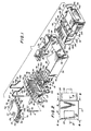
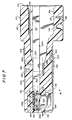
- the jack generally designated 10
- the jack comprises a housing 12 and a plurality of jack contacts 14 having pin portions 118 arranged in a pattern adapted to be received in corresponding receptacles of a socket in a printed circuit board, and contact portions 126 adapted to engage corresponding contact terminals of a modular plug connector 16 also constructed in accordance with the invention, an embodiment of which is best seen in Figs. 1 and 7-11.
- the jack also accommodates ground contacts 15 which are adapted to engage and electrically ground a shielding and grounding part 18 of housing 12 which is formed of electrically conductive material.
- the housing 12 is formed by an interlocked assembly of the shielding and grounding part 18, a contact guide part 20, a contact fixing part 22 and a contact stop part 24.
- parts 18-24 constitute a jack housing 12 which securely holds the plurality of jack contacts 14 and ground contacts 15 (except for their pin portions) entirely enclosed within the housing as described below and which defines an elongated receptacle or cavity 26 for receiving modular plug connector 16.
- the shielding and grounding part 18, best seen in Figs. 1 and 3-5, is preferably molded of a material which is electrically conductive and which provides good electromagnetic (EMI) and radio frequence (RFI) interference shielding, such as ABS with an aluminum flake filling or a known alloy resin.
- part 18 can be manufactured of a metallic material, such as zinc, by die casting techniques.
- Part 18 has substantially rectangular, sleeve-like configuration including opposed top and bottom walls 28 and 30 and opposed side walls 32. The walls extend from a front surface 34 of part 18 which constitutes the front surface of jack housing 12.
- the top and side walls 28 and 32 extend to a rear surface 36 of part 18 which constitutes the rear surface of jack housing 12.
- a relatively large rectangular notch 38 is centrally formed in top wall 28 which extends from rear surface 36 for a length somewhat less than one half the length of part 18 while a smaller notch 40 is formed in the rear end of each of the side walls 32.
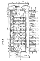
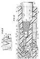
- Bottom wall 30 extends for a substantial distance and terminates at to a rear surface 42 situated at a substantially central region of a receptacle 26 as best seen in Fig. 5.
- the front surface 34 of part 18 is rounded at each of the inner edges of the respective walls to define an entrance into the receptacle 26 for the modular plug connector.
- a pair of parallel inner channels 44 are formed in respective side walls 32, each of which opens at front and rear surfaces 34 and 36.
- a first locking portion 46 having a rearwardly facing locking surface is provided in each inner channel 44 at its front end for locking the modular plug connector within the jack.
- a planar grounding portion 48 projects inwardly from each side wall 32 and extends forwardly from rear surface 36 a short distance.
- the downwardly facing surface of each grounding portion 48 is substantially coplanar with a downwardly facing surface of a respective inner channel 44 as best seen in Fig. 3 and is engaged by a respective one of the ground contacts 15 to electrically ground shielding and grounding part 18 as described in greater detail below.
- a second locking portion 50 having a forwardly facing locking surface for locking an assembly of the contact guide 20 and the contact fixing part 22 to shielding and grounding part 18 projects inwardly from each side wall 32 and extends vertically between the forwardmost region of a respective planar grounding portion 48 and top wall 28.
- Contact guide part 20 is molded of conventional dielectric plastic material and includes a block-shaped major portion 52, a shelf portion 64 projecting forwardly from the bottom of the front of major portion 52, a central platform portion 72 extending forwardly from the forward surface of shelf portion 64 and a pair of end retaining members 74 flanking central platform portion 72.
- Each end retaining member 74 has an upwardly facing support surface 75 and a vertical retaining portion 76.
- a plurality of parallel, equally spaced vertical guide slots 54 are defined at the front of major portion 52 by a plurality of spaced, forwardly extending vertical walls 55.
- Each vertical guide slot 54 communicates with the forward end of a respective horizontal groove 56 formed in the top surface 58 of the major portion 52 of contact guide part 20.
- the rear end of each horizontal groove 56 communicates with the top end of a respective vertical rectangular cross-section stepped bore 60 formed through contact guide part 20, the bottom end of which opens onto the lower surface 62 of contact guide part 20.
- Each of the stepped bores 60 are alternately situated in one of two parallel, transverse planes which are longitudinally spaced from each other in accordance with the desired pattern of the pin portions of the jack contacts.
- the horizontal grooves 56 alternate in length as best seen in Fig. 1.
- the shelf portion 64 has a plurality of horizontal guide slots 66 formed in its upper surface defined by a plurality of spaced forwardly extending vertical walls 67. Each horizontal guide slot 66 is aligned in a common plane with a respective one of the vertical guide slots 54 and the bottom wall of each horizontal guide slot 66 terminates at its forward end in a region 68 of increased thickness.
- a shallow recess 70 is formed in the upwardly facing surface of shelf portion 64 so that coplanar shoulders 71 are defined in vertical walls 67 as best seen in Figs. 1 and 5.
- Each pair of aligned vertical guide slots 54 and horizontal guide slots 66 associated horizontal groove 56 and stepped bore 60 serve to receive and position a respective jack contact 14 and guide the same upon engagement by a contact terminal of the modular plug connector as described below.
- a horizontal rail 78 projects outwardly from each side surface of major portion 52 of contact guide part 20, the horizontal rails 78 adapted to be received in corresponding inner channels 44 of shielding and grounding part 18 during assembly of the jack as described below.
- Each horizontal rail 78 has a blind vertical bore 80 and a through-bore 82 formed therein, a groove 84 formed in a top surface of each horizontal rail 78 interconnecting the top end of each respective pair of bores 80 and 82.
- Each pair of bores 80 and 82 and associated groove 84 serve to receive and position a respective ground contact 15.
- a pair of flanges 86 project laterally from the rear end of the side surfaces of major portion 52 beyond the end surfaces of respective horizontal rails 78.
- a pair of guide projections 114 extend upwardly from the top surface 58 of contact guide part 20 for fixedly positioning contact fixing part 22 with respective to contact guide part 20 during assembly of the jack.
- Posts 140 project downwardly from the lower surface 62 of contact guide part 20 which serve to mechanically affix the assembled jack to the printed circuit board.
- Contact stop part 24 may be formed of either a dielectric material, such as plastic, or electrically conductive material, such as aluminum, depending on its intended function.
- contact stop part 24 in all cases functions to limit the movement of the jack contacts 14 as described below and, where desired, also functions to electrically short or ground the jack contacts upon removal of the modular plug connector from the jack receptacle in which case it is made of a conductive material.
- Contact stop part 24 has a channel-shaped construction including a web 88, an upper flange 90 and a lower flange 94.
- An elongated notch 92 is formed in lower flange 94 and part way through web 88 and has a length slightly greater than the transverse dimension of central platform portion 72 of contact guide part 20 to define lower flange end portions 91a and 91b.
- a pair of ears 96a and 96b extend forwardly and outwardly from the respective edges of web 88.
- Contact fixing part 22 is also molded of conventional dielectric plastic material and has a generally planar rectangular shape including an upper planar portion 98, a shorter and wider lower planar portion 100 integral therewith, a pair of latch members 102 joined to the respective side surfaces of the lower planar portion 100 and five elongate, keys 104a - 104e which extend forwardly from the forward surface 105 of lower planar portion 100 a distance somewhat beyond the forward surface 107 of the upper planar portion 98.
- the upper planar portion 98 has transverse and longitudinal dimensions substantially equal to the corresponding dimensions of rectangular notch 38 formed in the top wall 28 of shielding and grounding part 18 and a thickness substantially equal to that of the top wall 28.
- the lower planar portion 100 has a length equal to the length of the top surface of the major portion 52 of contact guide part 20 so that, upon assembly, it overlies the vertical guide slots 54 as best seen in Fig. 5.
- a flange 106 depends downwardly from the rear end of the lower planar portion 100 which is adapted to interfit with a corresponding notch 108 formed at the rear end of major portion 52 of contact guide part 20.
- the lower planar portion 100 projects laterally beyond the upper planar portion 98 to define a pair of lateral extensions 110 in which openings 112 are formed adapted to align with and receive the guide projections 114 which extend upwardly from the top surface of the major portion 52 of contact guide part 20.
- Each latch member 102 includes an elongate portion which extends forwardly from the region at which it is joined to the respective lateral extensions 110 of the lower planar portion 100 and terminates at a locking portion 116 having a rearwardly facing surface which, upon assembly, is adapted to lockingly engage with the forwardly facing surface of the second locking portion 50 of the shielding and grounding part 18.
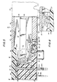
- the jack contacts 14 are preferably formed of suitable conductive material, such as phosphor bronze. In order to maintain a low profile for the jack, the contacts are preferably photoetched from relatively thin sheet material having a thickness, for example, of about 0,3 mm (.012 inches). As best seen in Fig. 5, each of the jack contacts 14 includes a pin portion 118, a bridging portion 120 extending at a right angle from pin portion 118, a rectilinear guide portion 122 connected to bridging portion 120 by a rounded pivot portion 124, a contact portion 126 forming an angle somewhat greater than 90° with guide portion 122 and a terminal stop portion 128.
- suitable conductive material such as phosphor bronze.
- the contacts are preferably photoetched from relatively thin sheet material having a thickness, for example, of about 0,3 mm (.012 inches).
- each of the jack contacts 14 includes a pin portion 118, a bridging portion 120 extending at a right angle from pin portion 118, a
- each jack contact 14 has a length which is greater than the height of the major portion 52 of contact guide part 20 so that when the pin portion 118 is located within its respective stepped bore 60, an end region thereof extends beyond the lower surface 62 to define a jack contact pin 118a adapted for insertion into the socket of the printed circuit board.
- the bridging portion 120 of each contact has a length which corresponds to the length of the horizontal groove 56 in which it is situated. Thus, the bridging portion 120 of the jack contacts 14 will have one of either a shorter or longer length depending upon in which of the two sets of vertical stepped bores 60 the pin portion 118 is situated.
- each jack contact 14 is formed so as to define an angle of about 15° with the horizontal when in its normal position as seen in Fig. 5 to comply with governmental regulations.
- contact portion 126 forms an angle of about 105° with guide portion 122. This angle may be within the range of between about 97° and 112°.
- Contact portion 126 is preferably coined during fabrication to further enhance electrical engagement with a respective contact terminal of the modular plug connector as described below.
- the ground contacts 15 are formed of wire stock and include a pin portion 130, a bridging portion 132 and a fixing portion 134.
- the pin portion 130 is sufficiently long so that when it is located within through-bore 82, an end region extends beyond the lower surface 62 to define a ground contact pin 130a adapted for insertion into a grounded socket of the printed circuit board.
- the bridging portion 132 is adapted to lie within groove 84 with a portion thereof extending slightly above the plane of the top surface of the respective horizontal rail 78 for engagement with conductive shielding and grounding part 18 as described below.
- the fixing portion 134 is captured within the blind vertical bore 80.
- the jack contacts 14 are first associated with contact guide part 20 by inserting their pin portions 118 through the tops of respective stepped bores 60.
- the bridging and guide portions 120 and 122 of each contact are received in respective horizontal grooves 56 and vertical guide slots 54 respectively.
- the pin portions 130 of ground contacts 15 are similarly inserted through the through-bores 82 until their bridging and fixing portions 132 and 134 are received in grooves 84 and blind vertical bores 80 respectively.
- jack contact pins 118a and ground contact pins 130a thereby project below the lower surface 62 of contact guide part 20.
- the contact fixing part 22 is then located over the top surface 58 of contact guide part 20 and is assembled thereto with guide projections 114 of the contact guide part 20 being received in the openings 112 formed in the lateral extensions 110 of contact fixing part 22 to precisely position contact fixing part 22 with respect to contact guide part 20.
- the downwardly facing bottom surface 136 of contact fixing part 22 lies flush against the top surface 58 of contact guide part 20 to close the horizontal grooves 56 and thereby capture the bridging portions 120 of jack contacts 14 in place.
- the jack contacts are formed such that when positioned as described above in their unstressed state, the stop portion 128 of each contact is situated vertically over but not within a respective horizontal guide slot 66. In this connection the contact stop part 24 is then mounted to the assembly of the contact guide and fixing parts 20 and 22. Referring to Figs.
- the terminal stop portions 128 of jack contacts 14 are urged or flexed into their respective horizontal guide slots 66 whereupon contact stop part 24 is positioned such that the end region of shelf portion 64 is received within the channel of part 24 with the upper flange 90 being situated in the shallow recess 70 abutting coplanar shoulder 71 to thereby overlie the end regions of the horizontal guide slots 66 and with the lower flange end portions 94a and 94b underlying the end region of shelf portions 64.
- the elongated notch 92 which extends partially through the web 88 of contact stop part 24 provides a clearance through which the central platform portion 72 extends.
- the stop part 24 is retained in position through the location of ears 96a and 96b in the lateral recesses defined by end retaining members 74. Thus, movement of the stop part 24 in the forward direction is prevented by engagement of the free edges of ears 96a and 96b with the rearwardly facing surfaces of vertical retaining portions 76.
- the terminal stop portions 128 of jack contacts 14 are captured and held within the horizontal guide slots 66 by the upper flange 90 contact stop part 24 as seen in Fig. 5 with the contacts 14 being in a prestressed condition.
- This assembly consisting of the contact guide, contact fixing and contact stop parts 20,22 and 24 with the jack and ground contacts 14 and 15 located therein as described above, is then inserted into the shielding and grounding part 18 from the rear thereof as seen in Fig. 1.
- the horizontal rails 78 of contact guide part 20 are aligned with and inserted into respective inner channels 44 of shielding and grounding part 18 and the assembly is urged forwardly until the forward facing surface 138 of central platform portion 72 abuts against the rear surface 42 of bottom wall 30 of shielding and grounding part 18.
- the locking portions 116 of latch members 102 move into locking engagement with the second locking portions 50 of shielding and grounding part 18 to lock the assembly within the shielding and grounding part 18.
- the elongate keys 104a-104e extend forwardly within the receptacle of cavity 26 beneath the top wall 28 of shielding and grounding part 18 as seen in Figs. 3 and 5.
- the bottom surface of the planar grounding portions 48 of shielding and grounding part 18 are coplanar with the downwardly facing surfaces of inner channels 44.
- the upper surface of the portion of the horizontal rails 78 in which the grooves 84, which receive bridging portions 132 of ground contacts 15, are formed directly underlie and mate substantially flushly with the bottom surfaces of the respective planar grounding portions 48.
- the bridging portions 132 of ground contacts 15 protrude slightly beyond grooves 84 so that upon assembly the bridging portions 132 of the ground contacts engage the planar grounding portions of shielding and grounding part 18 as best seen in Fig. 3. In this manner, the conductive shielding and grounding part 18 is electrically connected to ground contacts 15.
- jack and ground contact pins 118a and 130a project downwardly from the lower surface 62 of contact guide parts 20 for insertion into an appropriate socket of a printed circuit board.
- the posts 140, integrally formed with contact guide part 20, extend downwardly to provide a rigid mechanical connection of the jack to the printed circuit board.
- the ground contact pins 130a are connected through the printed circuit board to ground to thereby connect the conductive shielding and grounding part 18 to ground.
- the two outermost jack contacts may be power transmitting contacts and therefore may be somewhat wider than the other jack contacts.
- the construction described above advantageously permits the jack to have an unusually low profile while complying with requirements specified by governmental regulations and satisfying the other objectives of the invention as described below.
- the available space between adjacent printed circuit boards into which the jack must fit is about 9,5 mm (.375 inches)
- the height of receptacle or cavity 26 of jack 10 is about 6.6 mm (.260 inches) with the height or thickness of the top and bottom walls 28 and 30 of shielding and grounding part 18 being about 0.76 mm (.030) and 1.8 mm (.070 inches) respectively.
- the height of the major portion 52 of shielding and grounding part 20 is about 7.2 mm (.285 inches) while the total height of contact fixing part 22 including the upper and lower planar portions is about 2.2 mm (.085 inches).
- the jack not only has such a low profile as to allow its use in the limited spaces described above but also provides extremely effective EMI/RFI shielding for the connector to attenuate any radiation passing into and out from the jack as well as reliable grounding for shield terminating structure provided on the modular plug connector.
- the side walls 32 of the conductive shielding and grounding part 18 extend over the entire longitudinal extent of the receptacle or cavity 26.
- the top wall 28 of shielding and grounding part 18 overlies the entire longitudinal extent of the top of receptacle or cavity 26 except for the portion of rectangular notch 38 and the bottom wall 30, although terminating at rear surface 42, extends over a substantial longitudinal extent of the bottom of receptacle or cavity 26.
- the walls of the conductive shielding and grounding part substantially surround the plug receiving receptacle on all of its sides substantially over its length thereby providing effective EMI/RFI shielding.
- the inner surfaces of the conductive shielding and grounding part 18 bounding a substantial portion of the length of the receptacle on all of its sides, a reliable electrical engagement between shielding and grounding part 18 and a shield terminating collar surrounding a modular plug connector to ground the same as described below is assured.
- the height of the jack is defined by the distance between the outer surfaces of the top and bottom walls of the shielding and grounding part 18 and can be maintained at a minimum.
- the jack contacts are somewhat important in view of the low profile of the jack.
- the jack contacts are formed of relatively thin conductive sheet material, such as 0.3 mm (.012 inches) thick phosphor bronze sheet material, preferably by photoetching.
- conductive sheet material such as 0.3 mm (.012 inches) thick phosphor bronze sheet material, preferably by photoetching.
- each jack contact when mounted have sufficient resiliency so that when a modular plug connector is inserted into the jack receptacle and the contact portion of the jack contact is engaged by the edge of the flat contact terminal as described below, the jack contact will flex a sufficient amount so that a return force exists which urges the contact portion against the connector contact terminal with sufficient force to ensure a reliable electrical engagement.
- the contact portion 126 of the jack contact should normally form an angle of about 15° with the horizontal in accordance with governmental specifications.
- each jack contact 14 includes a rounded pivot portion 124 which subtends an angle of about 90°, the flexure of the jack contact effectively taking place around a point designated P in Fig. 5.
- the contact portion 126 normally should form an angle of about 15° with the horizontal. It has also been found that in order to assure sufficient springback forces, i.e. sufficient resiliency to ensure a reliable electrical engagement between the jack and connector contacts, the distance between pivot point P and the point of engagement, designated R in Fig.
- the contact portion 126 and the flat contact terminal 142 should be in the range of between about 3,8 mm (.15 inches) and 6.4 mm (.25 inches,) most preferably about 0.5 mm (.20 inches).
- the horizontal guide slots 66 can have a depth of about 1.4 mm (.056 inches) to allow sufficient room for movement of the contact stop portions 128 between their normal unflexed and flexed positions. This rather limited movement ensures adequate life for each jack contact.
- the jack contacts are preferably situated within the contact guide part 20 in a pre-stressed condition as described above to further ensure a reliable electrical engagement with the contact terminals of the modular plug connector.
- the jack contacts 14 are fully enclosed and rigidly supported within the jack housing 12 and are effectively electrically isolated from engagement with the shielding and grounding part 18 of the jack.
- the position and movement of the jack contacts are precisely controlled by guide slots 54 and 66.
- modular plug connector 16 is similar in several respects to the conventional connectors disclosed in the various patents mentioned hereinabove but differs in certain other respects.
- modular plug connector 16 includes a housing 150 formed as a rigid unipartite member of a suitable dielectric material by conventional injection molding techniques.
- the housing 150 has a closed forward free end 152, a cord-receiving rearward end 154 and a terminal-receiving side 156 for receiving flat contact terminals 142.
- the housing 150 defines a longitudinally extending cord-receiving cavity 158 which externally opens through a cord entrance opening 160 formed in the cord receiving rearward end 154 of housing 150.
- the cord-receiving cavity 158 includes a forward conductor-receiving portion 162 and a rearward enlarged jacket-receiving portion 164.
- the cord-receiving cavity 158 substantially encloses the entire end section of the cord with the terminal end portions of the conductors (having the outer jacket stripped therefrom) being received in the conductor-receiving portion 162 and the adjacent jacketed portion of the cord being received within the jacket-receiving portion 164.
- the cord conductors 166 are precisely positioned within the conductor-receiving portion 162 in a manner described below so that they are in direct aligned relationship with respective ones of a plurality of parallely spaced, longitudinally extending terminal-receiving slots 168 formed through the terminal-receiving side 156 of the housing and which open onto the closed forward free end 152 thereof so as to communicate with the conductor-receiving portion 162 of cavity 158.
- a pair of inwardly extending shoulders 170 and 172 are situated at about the mid-height of each slot 168.
- Each flat contact terminal 142 is constructed of electrically conductive material, such as gold plated phosphor bronze, and includes a flat conductive portion having a pair of insulation-piercing tangs 174 and a pair of outwardly extending barbs 176 and 178.
- electrically conductive material such as gold plated phosphor bronze
- the housing 150 includes forward and rear housing sections 180 and 182, the forward housing section 180 having reduced dimensions corresponding to the dimensions of the jack receptacle or cavity 26 so as to be insertable therewithin.
- the rear housing section 182 has increased dimensions sufficient to accommodate the jacket-receiving portion 164 of the cord-receiving cavity 158 and is adapted to remain external of the jack receptacle or cavity 26 as best seen in Fig. 10.
- the forward housing section 180 has a height of about 0.8 mm (.255 inches) while the rear housing section 182 has a height of about 9.5 mm (.375 inches).
- a pair of elongate latching members 184 are connected to the rearward ends of the lateral sides of the rear housing section 182 and extend forwardly to terminate at forward locking portions 186 having rearwardly facing locking surfaces which lie in a plane just forward of the intersection of the forward and rear housing sections. Upon insertion of the modular plug connector into the jack receptacle, the locking surfaces of the forward locking portions 186 engage the locking surfaces of the first locking portions 46 of the jack.
- the housing 150 includes means for securing the connector to the cord.
- a jacket anchoring member 188 is integrally formed within a well provided in the bottom wall of the rear housing section 182.
- Jacket anchoring member 188 is connected to the rear housing section 182 along its forward edge by a plastic hinge 190 and along its rearward edge by a frangible portion 192 which supports the jacket anchoring member 188 when a cord is received within cord-receiving cavity 158.
- the frangible portion 192 is constructed so as to shear upon the application of an inwardly directed force so that the jacket anchoring member 188 pivots about plastic hinge 190 to engage the cord jacket as shown by the dotted line configuration in Fig. 10.
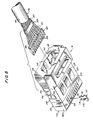
- the cord comprises a multi-conductor round cable comprising a plurality of insulated cord conductors 166.
- the cord conductors 166 are engaged within an outer jacket 198.
- a radiation shield 200 constituting a sleeve formed of braided conductive filaments is situated between the cord conductors 166 and the surrounding outer jacket 198 along substantially the entire length of cord 196.
- a terminal length of the outer jacket 198 is stripped from the cord to expose the radiation shield 200.
- a shorter terminal length of the radiation shield 200 is then removed to expose end portions of the insulated cord conductors 166 while a short length of the radiation shield 200 remains exposed.
- a conductive ferrule 202 formed of thin conductive material is then crimped over the end region of the exposed portion of radiation shield 200 so as to electrically engage the same over a full 360° of its circumference as best seen in Fig. 8.
- the exposed ends of the insulated cord conductors 166 are inserted into respective parallel, longitudinally extending bores 203 formed in a plastic load block 204 (Fig. 8) which serves to facilitate positioning of the cord conductors 166 in the conductor-receiving portion 162 of cord-receiving cavity 158.
- the plastic load block 204 has an outer substantially rectangular configuration adapted to be snugly received in the conductor-receiving portion 162 of cord-receiving cavity 158. Referring to Figs. 1, 8 and 10, a pair of opposed side channels 205a and 205b are formed in cord-receiving cavity 158 extending along its entire length.
- the side channels 205 are configured so as to provide sufficient space that the plastic load block 204 can be received into the cord entrance opening 160 and pushed forwardly until it reaches its forwardmost position in the conductor-receiving portion 162 with its lateral ends supported in the respective side channels 205.
- the upper and lower surfaces of the plastic load block In its final position, substantially mate with the upper and lower surfaces of the conductor-receiving portion 162 and the forward end of the load block engages the inner surface of the forward closing wall of the plug so that the load block is snugly held in position.
- the longitudinally extending bores 203 are precisely formed in plastic load block 204 so that when the plastic load block is positioned within the conductor-receiving portion as described above, each longitudinally extending bore 203 and, therefore, each cord conductor 166 inserted therewithin, is precisely aligned with a respective one of the terminal receiving slots 168.
- the outer wall of one side channel 205b is formed at a certain angle and one of the lateral sides of the plastic load block is formed to slant at a corresponding angle. Thus, if it were attempted to insert plastic load block 204 into the cord receiving cavity in the incorrect orientation, the block would not fit into the respective channels.
- a plurality of parallel, longitudinally extending channels 206 are formed in the surface of plastic load block 204 which faces the terminal receiving slots 168 of modular plug connector 16.
- Each longitudinally extending channel 206 is aligned with and directly overlies a corresponding longitudinally extending bore 203. Accordingly, each longitudinally extending channel will align with a respective one of the terminal receiving slots.
- the plastic load block 204 serves to position each cord conductor 166 of cord 196 in precise alignment with a terminal receiving slot 168 of the modular plug connector.
- the insulation piercing tangs 174 thereof pass through a respective longitudinally extending channel 206 in the plastic load block and pierce a thin layer of plastic to enter a longitudinally extending bore 203 to electrically engage the cord conductor 166 located therewithin in a solderless connection.
- the modular plug connector is provided with means for electrically terminating the radiation shield 200.
- the cord-receiving cavity 158 defines a shield-terminating portion 250, outlined in phantom, between the conductor-receiving portion 162 and the jacket-receiving portion 164.
- the cord 196 is terminated as described above in a manner such that the conductive ferrule 202 will be situated in the shield-terminating portion 250 of cord-receiving cavity 158 when the plastic load block 204 with cord conductors 166 inserted in longitudinally extending bores 203 is situated in its forwardmost position as seen in Fig. 10.
- the upper wall of the forward housing section 180 of connector housing 150 has an elongate latch member 194 formed therein overlying and extending transversely over the substantial width of the shield-terminating portion 250 of the cord-receiving cavity 158.
- Elongate latch member 194 is connected to the housing 150 by a pair of thinned webs 194a and 194b (Fig. 7) which are adapted to facture upon an inward driving force being applied to elongate latch member 194.
- the forward housing section 180 of the modular plug connector 16 is encircled substantially around its entire circumference by a frame or collar 208 formed of a thin sheet of conductive material, such as a copper based nickel alloy.
- the conductive sheet material is pre-formed into the shape of a rectangular collar and then positioned over the housing section 180 so that the collar is received in a shallow recess formed in the outer surfaces therein.
- the transverse free end regions 210 of the conductive sheet are bent inwardly and captured within a slot or groove 212 formed in the side 180a of the forward housing section 180 as seen in Fig. 11.
- a through-slot 252 is formed in the other side 180b of forward housing section 180 which communicates with the shield-terminating portion 250 of cord-receiving cavity 158.
- Through-slot 252 has a relatively short longitudinally extending width and is formed by molding the plug housing with a cutout 216 (Fig. 11) at the lower corner region thereof at side 180b, the cutout having a relatively short longitudinal extent and opening into the shield-terminating portion 250 to define a first shoulder 254.
- a second cutout 256 (Fig. 11) is formed in the forward housing section 180 extending upwardly from the bottom thereof adjacent side 180a, second cutout 256 opening into the shield-terminating portion 250 at its transversely opposite side to define a second shoulder 258.
- the lower surfaces of shoulders 254 and 258 lie in a plane spaced a short distance from the plane of the bottom surface 250a of the shield-terminating portion 250 of cord receiving cavity 158.
- a portion of the conductive frame or collar 208 extends into the shield-terminating portion 250 of cord-receiving cavity 158 in order to electrically engage the conductive ferrule 202 which itself is in electrical engagement with the radiation shield 200 throughout its circumference.
- a contact strip portion 214 is formed from frame or collar 208 by severing the conductive sheet along a pair of parallel lines which extend transversely over the top surface of forward housing section 180 on either side of elongate latching member 184 and which continue part way down the side 180b terminating in the region of through-slot 252 and a connecting end line.
- the contact strip portion 214 so formed is bent at fold line 260 and inserted into through slot 252 as best seen in Fig.
- the free end region of contact strip portion 214 is situated under second shoulder 258 to fix the same in place.
- the part of the area of the frame or collar 208 which is vacated by the contact strip portion 214 overlies the elongate latch member 194 and provides access thereto during termination of the cord.
- the cord end With the cord end prepared as described above and shown in Fig. 8, it is inserted into the cord-receiving cavity 158 so that the plastic load block 204 is positioned at the forwardmost position of the conductor-receiving portion 162 of cord-receiving cavity 158.
- the construction of the plastic load block 204 is such that each cord conductor 166 is situated in aligned relationship with a respective terminal-receiving slot 168.
- the conductive ferrule 202 which is in electrical engagement with the radiation shield 200 over a full 360° is positioned within the shield-terminating portion 250 at a location directly beneath the elongate latch member 194 and at the same time in electrical engagement with the contact strip portion 214 of collar or frame 208.
- the flat contact terminals 142 are inserted into terminal receiving slots 168 whereupon the insulation-piercing tangs 174 of each terminal pierce through the material of the plastic load block 204 and then through a respective cord conductor 166 to effect electrical engagement therewith.
- the jacket anchoring member 188 is driven downwardly to its locked position.
- the elongated latch member 194 is driven downwardly to the position illustrated in Fig. 10.
- the action of elongated latch member 194 is two-fold, firstly compressing the underlying conductive ferrule 202 onto the radiation shield 200 and, secondly, urging the conductive ferrule with a positive force against the contact strip portion 214.
- the 360° electrical engagement of the radiation shield by the conductive ferrule is further enhanced while at the same time providing a positive electrical coupling of the conductive ferrule and the contact strip portion 214.
- the conductive collar or frame 208 which encircles the modular plug connector over a full 360° of its transverse circumference is electrically coupled to and terminates radiation shield 200.
- the modular plug connector is provided with means for terminating the EMI/RFI shield of a cord as a part of the modular plug connector itself so that electromagnetic and radio frequency interference-causing signals conducted through the shield can be conducted through the modular plug connector to be grounded through coupling with a grounded part of the jack as described below.
- a plurality (three shown) of leaf-spring portions 224 are integrally formed in the bottom side of collar or frame 208 and a plurality of upwardly extending dimples 218 are formed in the top side thereof.
- Each of the leaf-spring portions 224 extend rearwardly and slightly outwardly and function to enhance the electrical engagement between the shield terminating collar or frame 208 and the shielding and the inner surfaces of the top and bottom walls of the shielding and grounding part 18 of the jack upon insertion of the plug.
- Each of the first leaf-spring portions 224 terminates at an inwardly directed portion 222 which is disposed within a respective cavity 220 which provides clearance for flexing of the spring portion.
- the modular plug connector 16 terminating the cord 196 as described above is inserted into the receptacle or cavity 26 of jack 10.
- a leading end of the outer edge of each flat contact terminal 142 engages the contact portion 126 of a respective jack contact 14 to effect electrical communication between the jack contacts and the respective cord conductors 166.
- the coining of the contact portions 126 of jack contacts 14 reduces abrasion during electrical engagement thereby approximating the characteristics of standard wire contacts such as are used in telephone jacks while at the same time permitting the jack contacts 14 to be formed of thin sheet metal stock to facilitate reduction in the height of the jack.
- Continued insertion of the plug causes the jack contacts 14 to flex from their rest positions (Fig.
- the outer surface of conductive collar or frame 208 surrounding the modular plug connector engages and electrically communicates with the conductive shielding and grounding part 18 of the jack 10 when the modular plug connector is inserted within the jack receptacle.
- This electrical engagement is enhanced by the dimples 218 and leaf-spring portions 224 which are resilient and flex inwardly upon engagement with shielding and grounding part 18 causing them to be continually urged with a positive force against the inner surfaces of the top and bottom walls of conductive shielding and grounding part 18.
- the sides of collar or frame 208 also at least partially engage the inner surfaces of the side walls of shielding and grounding part 18.
- the electromagnetic and radio frequency interference-causing signals and any electrostatic charge present in the radiation shield 200 will be conducted through the modular plug connector by the contact strip portion 214 to collar or frame 208 and then to the conductive shielding and grounding jack part 18.
- the electrical engagement between the collar or frame 208 and the shielding and grounding part 18 is enhanced by virtue of the construction described above wherein the collar surrounds the connector over substantially its entire circumference and engages the conductive shielding and grounding part 18 substantially over its entire inner circumference.
- the shielding and grounding part 18 is itself grounded through engagement of ground contacts 15 with the planar grounding portions 48 as described above.
- the ground contacts 15 are grounded through ground contact pins 130a which are inserted into grounded openings in the socket of the printed circuit board.
- the shielding and grounding part 18 extends from the forward end of the jack substantially to its rearward end provides additional shielding for the modular plug connector as does the collar or frame 208 which substantially surrounds the connector.
- the jack and modular plug connector have such low profiles as to permit connection to printed circuit boards which are stacked one over the other in closely spaced relationship.
- Unlocking of the modular plug connector from the jack is accomplished by pressing the elongate latching members 184 inwardly to disengage the forward locking portions 186 from the first locking portions 46 of the jack whereupon the modular plug connector can be withdrawn from the jack receptacle.
- the contact stop part 24 may be formed of metallic conductive material so that upon withdrawal of the modular plug connector the terminal stop portions 128 of jack contacts 14 engage the upper flange 90 of contact stop part 24 to ground any static charge which may remain on the contacts.
- the jack is preferably provided with means for permitting selective use of only certain appropriate modular plug connectors therewith.
- each of the five elongate keys 104a-104e is formed in one of two positions, the alternate position of each elongate key being laterally displaced from the one illustrated and shown in phantom in Fig. 3. This is easily accomplished through the provision and removal of appropriate inserts in the mold from which the contact fixing part 22 of the jack is formed.
- the modular plug connector 16 is molded with corresponding keyways 226a-226e, each keyway 226 being appropriately situated so as to receive a corresponding one of the elongate keys 104 as seen in Fig. 10.
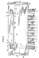
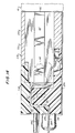
- Jack 230 is adapted such that the contact pins extend from the rear surface of the jack and is used where the connector is to be inserted within the jack in a downward direction.
- Jack 230 includes a housing 232 formed of a plurality of parts which correspond to those which constitute jack housing 12, namely a shielding and grounding part 234, a contact guide part 236, a contact fixing part 238 and a contact stop part 240.
- the shielding and grounding part 234 is essentially identical to the shielding and grounding part 18 and is formed of a conductive material.
- the contact guide part 236 is similar to contact guide part 20 with the exception that a substantial recess 242 is formed in the rearward end portion thereof in which a plurality of vertical grooves of alternating lengths are formed. As seen in Fig. 12, the recess 242 includes a plurality of downwardly extending portions 244.
- the contact fixing part 238 is similar to the contact fixing part 22 but differs therefrom in that its rear end includes downwardly extending projections configured so as to mate with the recess 242 of the contact guide part 236.
- the cooperation of the alternating recesses 243 in the contact guide part 236 and the projections 246 of the contact fixing part define a series of passages through which portions of the jack contacts extend so as to exit from the jack housing at the rear face thereof.
- the various components of jack 230 which correspond to components of jack 10 are marked with corresponding reference numerals, primed.
Landscapes
- Details Of Connecting Devices For Male And Female Coupling (AREA)
- Coupling Device And Connection With Printed Circuit (AREA)
- Connector Housings Or Holding Contact Members (AREA)
- Containers And Packaging Bodies Having A Special Means To Remove Contents (AREA)
Claims (41)
- Prise femelle (10) adaptée pour la connexion à une plaquette de circuits imprimés ou analogue, pour un connecteur de prise mâle modulaire (16), présentant:
un boîtier de prise femelle (12) pour loger le connecteur de prise mâle modulaire (16),
une fiche femelle (26), présentant une ouverture d'entrée (160) sur une extrémité longitudinale (34) du boîtier (12); et
une pluralité de contacts de prise femelle (14, 15), chaque contact présentant une première partie de broche (130, 118) comprenant une partie de broche (118a), s'étendant extérieurement au boîtier adapté pour la connexion à une plaquette de circuits imprimés ou analogue, et une seconde partie de contact (126), s'étendant dans ladite fiche femelle (26) adaptée pour la mise en contact par un contact du connecteur de prise mâle modulaire (16),
caractérisée en ce que:
le connecteur de prise mâle modulaire présente un moyen de contact se terminant en un écran en câble,
le boîtier de prise femelle est formé par une pluralité de parties de prise femelle (14, 15, 18, 20, 22, 24) adaptées pour s'installer les unes entre les autres de manière bloquée, afin de définir la fiche femelle allongée (26), et
la première partie des parties de prise mâle constitue une partie de mise à la terre et d'écrantage (18), formée en un matériau conducteur de l'électricité, et présentant des parois supérieure (28), inférieure (30) et latérales (32) définissant un organe fermé comme une gaine isolante, chacune desdites parois présentant une surface intérieure s'étendant longitudinalement, dont au moins une partie substantielle contient ladite fiche femelle (26) de prise mâle, de sorte qu'une partie substantielle de la longueur de ladite fiche femelle allongée est reliée sur tous ses côtés, grâce au matériau conducteur de l'électricité desdites parties de mise à la terre et d'écrantage (18). - Prise femelle selon la revendication 1, dans laquelle lesdites parois supérieure (28) et inférieure (30) de ladite partie de mise à la terre et d'écrantage (18) présentent des surfaces extérieures, et dans laquelle ledit boîtier de prise femelle (12) est de grande dimension, pratiquement égale à la distance entre lesdites surfaces extérieures desdites parois supérieure (28) et inférieure (30).
- Prise femelle selon la revendication 1 ou 2, dans laquelle chacun desdits contacts de prise femelle (14, 15) comprend au moins une partie supplémentaire (15), et dans laquelle chacune desdites parties de contact supplémentaires sont entièrement contenues à l'intérieur dudit boîtier de prise femelle.
- Prise femelle selon l'une quelconque des revendications précédentes, dans laquelle lesdites parois supérieure (28), inférieure (30) et latérales (32), de ladite partie de mise à la terre et d'écrantage (18), entourent sensiblement ladite prise mâle qui reçoit la fiche femelle (26) sur tous ses côtés, pratiquement sur toute sa longueur.
- Prise femelle selon l'une quelconque des revendications précédentes, dans laquelle une seconde partie de ladite pluralité de parties de prise femelle constitue une partie de guide de contact (20), présentant des surfaces supérieure (58), inférieure, arrière et avant, lesdites surfaces inférieure et arrière constituant les parties d'une surface inférieure et arrière dudit boîtier de prise femelle (12), respectivement, et des moyens de guide de contact de prise femelle (60, 56, 54) formés dans ladite partie de guide de contact (20), pour recevoir et guider les parties correspondantes des contacts de prise femelle (14, 15) respectifs.
- Prise femelle selon la revendication 5, dans laquelle lesdites moyens de guide de contact de prise femelle (60, 56, 54, 84) comprenant une pluralité d'alésages (60), chacun s'ouvrant à ladite surface supérieure de ladite partie de guide de contact (20), pour recevoir ladite partie de broche (130, 118) d'un contact de prise femelle (14, 15) respectif, une pluralité de canaux (56), formés sur ladite surface supérieure (58), chaque canal (56) communiquant avec un alésage (60) respectif, pour recevoir une première partie de pontage (120) supplémentaire d'un contact de prise femelle (54) respectif, et une pluralité de premières rainures (54), formées sur ladite surface avant, chacune de ladite première pluralité de rainures (54) communiquant avec un canal (56) respectif, pour recevoir et guider une seconde partie de guide supplémentaire d'un contact de prise femelle (14, 15) respectif.
- Prise femelle selon la revendication 6, dans laquelle ladite partie de guide de contact (20) comprend en outre une partie de rayon (64), s'étendant à partir de ladite surface avant, une pluralité de secondes rainures (66), formées sur ladite partie de rayon (64), chaque seconde rainure (66) alignée dans un plan commun avec une fente correspondante desdites premières rainures (54), pour recevoir et guider une troisième partie de borne de repos (128) supplémentaire d'un contact de prise femelle (14) respectif.
- Prise femelle selon la revendication 7, dans laquelle une troisième partie desdites parties de prise femelle constitue une partie de repos de contact (24), présentant une partie de bride (90), qui recouvre les zones d'extrémité (71) desdites secondes rainures (66), afin de capturer lesdites parties de borne de repos (128) desdits contacts de prise femelle (14) dans lesdites secondes rainures (66).
- Prise femelle selon la revendication 5, 6, 7 ou 8, dans laquelle ladite partie de guide de contact (20) comprend un couple de rails (78) s'étendant longitudinalement, chaque rail s'étendant transversalement à partir de la surface latérale respective de ladite partie de guide de contact, et dans laquelle un couple de rainures (44) est formé dans lesdites surfaces intérieures desdites parois latérales (32), de ladite partie de mise à la terre et d'écrantage (18), chaque rainure (44) recevant un rail respectif desdits rails (78).
- Prise femelle selon la revendication 1, comprenant en outre un moyen pour relier électriquement ladite partie de mise à la terre et d'écrantage (18), afin de relier à la terre la connexion de ladite mise à la terre à une plaquette de circuits imprimés ou analogue.
- Prise de terre selon la revendication 10, dans laquelle ledit moyen de connexion à la terre comprend au moins un contact de terre (15), présentant une première partie (130) qui définit une broche s'étendant extérieurement du boîtier, pour la connexion à la terre, dans une plaquette de circuits imprimés ou analogue, et une seconde partie (132) en alignement électrique avec ladite partie de mise à la terre et d'écrantage (18).
- Prise femelle selon la revendication 11, dans laquelle une seconde partie de ladite pluralité de parties de prise femelle constitue une partie de guide de contact (20), ladite partie de guide de contact présentant un alésage formé au travers, qui s'ouvre sur une surface de cette partie, et un canal (84), formé dans ladite surface communiquant avec ledit alésage, ledit alésage recevant ladite première partie dudit contact de terre (15), et ledit canal (84) recevant ladite seconde partie dudit contact de terre (15), et dans laquelle ladite partie de mise à la terre et d'écrantage (18) comprend une partie de mise à la terre, présentant une surface qui recouvre ladite surface de partie de guide de contact, et entrant électriquement en contact avec ladite première partie dudit contact de terre (15).
- Prise femelle selon l'une des revendications précédentes, dans laquelle une partie de ladite pluralité de parties de prise femelle constitue une partie de fixation de contact (22), comprenant une partie planaire (98, 100) qui recouvre ladite surface supérieure (58) de ladite partie de guide de contact (20), et qui recouvre les parties desdits contacts de prise femelle (14), logés dans ledit moyen de guide de contact de prise femelle (60, 56, 54), afin de confiner les parties de contact de prise femelle à l'intérieur dudit moyen de guide.
- Prise femelle selon la revendication 13, comprenant en outre un moyen pour monter ladite partie de fixation de contact (22) sur ladite partie de guide de contact (20), en relation mutuelle fixée précise afin de former un sous-ensemble.
- Prise femelle selon la revendication 14, dans laquelle ledit moyen de montage comprend des parties en saillie (114), formées sur la première desdites parties de guide de contact et de fixation de contact, et des ouvertures (112), formées sur l'autre desdites parties de guide de contact et de fixation de contact, adaptées pour loger lesdites parties en saillie (114).
- Prise femelle selon la revendication 14 ou 15, comprenant en outre des moyens de verrouillage (102, 116, 50), formés sur ladite partie de fixation de contact (22) et la partie de mise à la terre et d'écrantage (18), pour connecter ledit sous-ensemble desdites parties de fixation de contact (22) et de guide de contact (20) à ladite partie de mise à la terre et d'écrantage (18).
- Prise femelle selon la revendication 13, 14, 15 ou 16, dans laquelle ladite partie de fixation de contact (22), comprend une partie planaire supérieure (98), adaptée pour s'installer dans un cran (38), formé dans ladite paroi supérieure (28) de ladite partie de mise à la terre et d'écrantage (18), ladite partie planaire supérieure (98) présentant une surface supérieure pratiquement coplanaire avec lesdites surfaces supérieures de ladite partie de mise à la terre et d'écrantage.
- Prise femelle selon la revendication 13, 14, 15, 16 ou 17, dans laquelle ladite partie de fixation de contact (22) comprend une partie planaire inférieure (100), présentant une surface avant (105), et comprenant en outre une pluralité de clés (104) s'étendant depuis ladite surface avant dans ladite fiche femelle (26) de logement de prise mâle, chaque clé étant située dans l'une des deux variantes de position.
- Prise femelle selon l'une des revendications 2 à 18, dans laquelle ladite dimension de hauteur de ladite prise femelle ne dépasse pas à peu près 9,525 mm (0,375 pouces).
- Prise femelle selon la revendication 1, 2, 3 ou 4, dans laquelle la seconde partie de ladite pluralité de parties de prise femelle constitue la partie de guide de contact (22), présentant les surfaces supérieure (58) et avant, la pluralité d'alésages (60), s'ouvrant chacun à ladite surface supérieure (58) de ladite partie de guide de contact (229), et logeant la partie de broche (118, 130) du contact respectif desdits contacts de prise femelle (14, 15), la pluralité de canaux (56), formés dans ladite surface supérieure, chaque canal communiquant avec un alésage respectif, et s'étendant vers ladite surface avant de ladite partie de guide de contact, et la pluralité de rainures de guide (54), formés sur ladite surface avant de ladite partie de guide de contact (22), chaque rainure de guide (54) alignée avec un canal respectif desdits canaux (56), et dans laquelle chaque contact desdits contacts de prise femelle (14, 15) comprend une partie de guide de prise femelle située dans la rainure respective desdites rainures de guide, la partie de pontage de prise femelle (120) située dans le canal respectif reliant lesdites broche et parties de guide, et en formant pratiquement des angles droits avec elles, et dans laquelle la partie de contact de prise femelle (126) s'étend depuis une extrémité d'une partie de guide de prise femelle respective, en formant avec elle un angle qui est supérieur à à peu près 90°.
- Prise femelle selon la revendication 20, dans laquelle ledit angle, formé entre lesdites parties de contact de prise femelle et de guide de prise femelle, est compris dans la plage située entre à peu près 97° et 112°.
- Prise femelle selon la revendication 21, dans laquelle ledit angle est d'à peu près 105°.
- Prise femelle selon la revendication 20, 21 ou 22, dans laquelle chaque contact de prise femelle comprend la partie de borne de repos (128), et ladite partie de guide de contact (22) comprend en outre la pluralité de secondes rainures de guide (66), chacune desdites secondes rainures de guide logeant la partie de borne de repos (128) du contact de prise femelle (14) respectif, et le moyen (24) servant à capturer chacune desdites parties de borne de repos (128) dans la seconde rainure (66) respective.
- Prise femelle selon l'une des revendications précédentes, dans laquelle chacun desdits contacts de prise femelle (14, 15) est fabriqué en matériau en feuille conductrice.
- Prise femelle selon la revendication 20, 21, 22, 23 ou 24, dans laquelle au moins ladite partie de contact de chaque contact de prise femelle est doté d'arêtes vives.
- Connecteur de prise mâle modulaire (16) situé à l'extrémité d'un câble (196), le câble présentant une pluralité de conducteurs isolés (166) compris dans une chemise extérieure (198), présentant un boîtier diélectrique (150), présentant une paroi supérieure, une paroi inférieure opposée de logement de borne, et un couple de parois latérales opposées (180), lesdites parois présentant des surfaces extérieures respectives, une extrémité libre avant (152) et une extrémité arrière logeant le câble, présentant une ouverture d'entrée de câble (160) formée en son sein, et s'ouvrant dans une cavité de logement de câble (158), formée dans le boîtier (150), ladite cavité de logement de câble (158) présentant une partie avant de logement de conducteur (162) et une partie arrière de logement de chemise (164), une pluralité de rainures de contact de logement de borne (168), formées dans ladite paroi inférieure de logement de borne, communiquant avec ladite partie de logement de conducteur (162) de ladite cavité de logement de câble (158), pour recevoir des bornes de contact plates (142), adaptées pour le contact électrique avec les conducteurs respectifs des conducteurs de câble (166),
caractérisé par:
un écran conducteur (200), situé entre la chemise et les conducteurs et entourant ces derniers, et
un moyen d'écrantage se terminant en contact (208, 210, 214, 250), pour le contact électrique avec l'écran en câble (200), et adapté pour venir au contact électrique d'une partie d'une prise femelle (10), fabriquée en un matériau conducteur de l'électricité, lors de l'insertion du connecteur de prise mâle modulaire (16) dans la prise femelle (10), ledit moyen d'écrantage se terminant en contact comprenant l'organe (208), fabriqué en matériau en feuille conducteur de l'électricité, comprenant une partie extérieure qui recouvre une zone de la surface extérieure d'au moins une desdites parois supérieure, inférieure et latérale, et la partie de contact (214), d'un seul tenant avec ladite partie extérieure, s'étendant dans ladite cavité de logement de câble, en ouvrant le moyen (252), formé dans une desdites parois latérales de boîtier. - Connecteur de prise mâle selon la revendication 26, dans lequel ledit moyen d'écrantage se terminant en contact comprend un organe en forme de collier (208), et dans lequel ladite partie extérieure comprend les parties supérieure, inférieure et latérales recouvrant les zones des surfaces extérieures desdites parois de boîtier supérieure, inférieure et latérales respectivement, de manière à entourer la circonférence dudit boîtier.
- Connecteur de prise mâle selon la revendication 26 ou 27, dans lequel ladite partie de contact dudit moyen d'écrantage se terminant en contact comprend une partie de bande de contact (214), s'étendant à travers une rainure, formée dans une des parois desdites parois latérales de boîtier, dans ladite cavité de logement de câble (158), ladite partie de bande contact (214) situé contiguë à une surface (250a), en définissant une partie se terminant en écran (250) de ladite cavité de logement de câble (158).
- Connecteur de prise mâle selon la revendication 26, dans lequel ladite partie extérieure dudit moyen d'écrantage se terminant en contact est formé comme l'organe en collier (208), avec des zones transversales à extrémité libre, capturées dans une rainure qui est formée dans une paroi latérales dudit boîtier (150), et dans lequel ladite partie extérieure dudit organe en collier comprend les parties supérieure, inférieure, et latérales, qui recouvrent les zones des surfaces extérieures desdites parois de boîtier supérieure, inférieure et latérales respectivement, de manière à entourer la circonférence dudit boîtier (150), et dans lequel ladite partie de contact dudit moyen d'écrantage se terminant en contact comprend la partie de bande de contact (214), s'étendant dans ladite cavité de logement de câble (158), à travers une rainure, formée dans l'autre paroi desdites parois latérales de boîtier.
- Connecteur de prise mâle selon la revendication 26, 27, 28 ou 29, comprenant en outre un moyen de verrouillage (194) s'étendant pratiquement transversalement, formé dans une desdites parois supérieure et inférieure dudit boîtier (150), à un endroit pratiquement aligné avec ladite partie se terminant en écran (250) de ladite cavité de logement de câble (158), dans laquelle ladite partie de contact dudit moyen d'écrantage se terminant en contact s'étend, ledit moyen de verrouillage (194) étant relié audit boîtier (150), par un moyen déformable afin de permettre audit moyen de verrouillage d'être entraîné dans ladite cavité de logement de câble (158).
- Connecteur de prise mâle selon la revendication 26, 27, 28, 29 ou 30, dans lequel ladite partie extérieure dudit moyen d'écrantage se terminant en borne comprend au moins une desdites parties supérieure et inférieure recouvrant les zones des surfaces extérieures desdites parois de boîtier supérieure et inférieure respectivement, et un moyen de suspension (218), formé dans ladite partie extérieure, pour presser contre ladite partie de prise femelle (10), fabriquée en matériau conducteur de l'électricité, lors de l'insertion du connecteur de prise mâle modulaire (16) dans la prise femelle (10), de manière à obtenir de façon fiable le contact électrique entre ledit moyen d'écrantage se terminant en borne dans ladite partie de prise femelle.
- Connecteur de prise mâle selon la revendication 27, 28, 29, 30 ou 31, dans lequel des moyens de ressort à lames (224) sont formés dans au moins une desdites parties supérieure et inférieure de l'organe en collier (208), lesdits moyens de ressort à lames comprenant un segment s'étendant vers l'arrière, de ladite partie extérieure, incliné vers l'extérieur par rapport à ladite partie extérieure.
- Connecteur de prise mâle selon la revendication 27, 28, 29, 30, 31 ou 32, dans lequel des dents faisant saillie vers l'extérieur (218) sont formées dans au moins une desdites parties supérieur et inférieure dudit organe en collier (208).
- Connecteur de prise mâle selon la revendication 26, 27, 28, 29, 30, 31, 32 ou 33, dans lequel un couple d'organes de verrouillage allongés (184) sont reliés d'un seul tenant audit boîtier, sur les surfaces extérieures des parois respectives de ses dites parois latérales, lesdits organes de verrouillage (184) étant reliés auxdites parois latérales, à des endroits adjacents à ladite extrémité arrière de logement de câble dudit boîtier (150), et s'étendant vers l'avant vers sa dite extrémité libre avant (152).
- Connecteur de prise mâle selon l'une des revendications 26 à 34, comprenant en outre un couple de canaux opposés (205), formés dans lesdites parois latérales dudit boîtier (150), lesdits canaux s'ouvrant dans ladite cavité de logement de câble (158), et s'étendant de façon continue depuis l'ouverture d'entrée de câble (160), à travers ladite partie de logement de conducteur (162) de ladite cavité.
- Connecteur de prise mâle selon la revendication 35, dans lequel la section transversale du premier desdits canaux (205a) est différente de la section transversale de l'autre desdits canaux (205b).
- Connecteur de prise mâle selon l'une des revendications 26 à 36, comprenant en outre une partie d'extrémité dudit câble (196), présentant la chemise (198) qui en est retirée pour présenter une partie dudit écran conducteur (200), et lesdits conducteurs (166), ladite extrémité de câble insérée dans ladite cavité de logement de câble (158), ladite partie exposée dudit écran conducteur (200) étant située dans la partie se terminant en écran (205) de ladite cavité de logement de câble (158), et le moyen d'écrantage se terminant en contact pour entrer en contact de façon électrique avec ladite partie exposée dudit écran conducteur, et adapté pour venir en contact électrique avec une partie de prise femelle fabriquée en matériau conducteur de l'électricité, lors de l'insertion du connecteur de prise mâle modulaire dans les prises femelles.
- Connecteur de prise mâle selon la revendication 37, dans lequel une ferrure déformable (202), fabriquée en matériau conducteur, entoure ladite partie exposée dudit écran conducteur (200), et est en contact électrique grâce à ladite partie de bande de contact (214).
- Ensemble de câbles, adapté pour se terminer par le connecteur de prise mâle modulaire (16), ce dernier comprenant le boîtier diélectrique (150), présentant les parois inférieure, supérieure et latérales de logement de borne, définissant l'extrémité avant libre de boîtier, l'extrémité arrière de logement de câble de boîtier, présentant l'ouverture d'entrée de câble (160) formée en son sein, et la cavité de logement de câble (158), présentant la partie avant de logement de conducteur (162), et les rainures de logement de borne (168), formées dans la paroi inférieure de boîtier, communiquant avec ladite partie de logement de conducteur de ladite cavité de logement de câble,
une pluralité de conducteurs isolés (166) compris dans la chemise extérieure (198), une partie d'extrémité dudit câble présentant ladite chemise extérieure qui en est retirée, afin d'exposer les zones d'extrémité desdits conducteurs isolés,
caractérisé par:
un bloc de charge (204), présentant une pluralité d'alésages parallèles (203), formés au travers dans une rangée linéaire, chaque alésage logeant une zone d'extrémité d'un conducteur isolé respectif, lesdits alésages étant espacés mutuellement entre eux suivant une distance égale à la distance existant entre les rainures de logement de borne, formées dans ledit boîtier. - Ensemble de câbles selon la revendication 39, dans lequel ledit bloc de charge comprend un couple de zones de bordure transversales opposées, la première zone de bordure transversale dudit bloc de charge présentant une configuration différente de celle de l'autre zone de bordure transversale.
- Ensemble de câbles selon la revendication 39 ou 40, dans lequel une pluralité de canaux parallèles (206) sont formés dans ledit bloc de charge, chaque canal aligné avec un alésage respectif desdits alésages de logement de conducteur.
Priority Applications (1)
| Application Number | Priority Date | Filing Date | Title |
|---|---|---|---|
| AT85109004T ATE70145T1 (de) | 1984-09-28 | 1985-07-18 | Steckbuechse und verbinder. |
Applications Claiming Priority (2)
| Application Number | Priority Date | Filing Date | Title |
|---|---|---|---|
| US06/655,696 US4653837A (en) | 1984-05-21 | 1984-09-28 | Jack and connector |
| US655696 | 1984-09-28 |
Publications (3)
| Publication Number | Publication Date |
|---|---|
| EP0175868A2 EP0175868A2 (fr) | 1986-04-02 |
| EP0175868A3 EP0175868A3 (en) | 1989-01-25 |
| EP0175868B1 true EP0175868B1 (fr) | 1991-12-04 |
Family
ID=24629985
Family Applications (1)
| Application Number | Title | Priority Date | Filing Date |
|---|---|---|---|
| EP85109004A Expired - Lifetime EP0175868B1 (fr) | 1984-09-28 | 1985-07-18 | Prise de courant et connecteur |
Country Status (6)
| Country | Link |
|---|---|
| US (1) | US4653837A (fr) |
| EP (1) | EP0175868B1 (fr) |
| JP (1) | JPH0628183B2 (fr) |
| AT (1) | ATE70145T1 (fr) |
| CA (1) | CA1234607A (fr) |
| DE (1) | DE3584810D1 (fr) |
Families Citing this family (38)
| Publication number | Priority date | Publication date | Assignee | Title |
|---|---|---|---|---|
| EP0614248B1 (fr) * | 1986-06-13 | 1996-11-20 | The Whitaker Corporation | Interface pour un réseau local (LAN) |
| US4838811A (en) * | 1986-08-22 | 1989-06-13 | Hirose Electric Co., Ltd. | Modular connector with EMI countermeasure |
| US4822303A (en) * | 1987-05-18 | 1989-04-18 | Hirose Electric Co., Ltd. | Electrical connector |
| US4906208A (en) * | 1987-05-15 | 1990-03-06 | Hirose Electric Co., Ltd. | Electrical connector |
| BR8900863A (pt) * | 1988-02-26 | 1989-10-17 | Amp Inc | Conjunto de conector eletrico para utilizacao na montagem em um componente eletrico |
| US4963098A (en) * | 1988-02-26 | 1990-10-16 | Amp Incorporated | Blind mate shielded input/output connector assembly |
| US4941833A (en) * | 1988-10-06 | 1990-07-17 | Burndy Corporation | Controlled impedance plug and receptacle |
| GB2227131A (en) * | 1989-01-10 | 1990-07-18 | Itt Ind Ltd | Shielded electrical connectors |
| US4921435A (en) * | 1989-06-02 | 1990-05-01 | Ford Motor Company | Blind mating connector having self-locating feature |
| US4927388A (en) * | 1989-09-29 | 1990-05-22 | Amp Incorporated | Electrical connector shell assembly and module retention clip |
| US5035632A (en) * | 1989-10-10 | 1991-07-30 | Itt Corporation | Card connector with interceptor plate |
| US4950172A (en) * | 1989-10-10 | 1990-08-21 | Itt Corporation | Connector with interceptor plate |
| US5156554A (en) * | 1989-10-10 | 1992-10-20 | Itt Corporation | Connector interceptor plate arrangement |
| JPH0722064Y2 (ja) * | 1989-12-04 | 1995-05-17 | ホシデン株式会社 | コネクタ |
| FR2693845B1 (fr) * | 1992-07-17 | 1997-01-31 | Air Lb International Sa | Connecteur electrique blinde perfectionne. |
| DE4238923C2 (de) * | 1992-11-19 | 1996-03-14 | Gaertner Karl Telegaertner | Stecker |
| FR2701605B1 (fr) * | 1993-02-10 | 1995-03-31 | Interconnection Inf | Connecteur mâle déconnectable pour réseau de communication. |
| ES2161819T3 (es) * | 1994-12-05 | 2001-12-16 | Whitaker Corp | Conector macho modular para transmision de datos a alta velocidad. |
| US5584709A (en) * | 1995-01-30 | 1996-12-17 | Molex Incorporated | Printed circuit board mounted electrical connector |
| US5800192A (en) * | 1996-08-30 | 1998-09-01 | Berg Technology, Inc. | Receptacle with integral sensor device |
| US5899770A (en) * | 1996-11-05 | 1999-05-04 | Hirose Electric Co., Ltd. | Modular plug and modular jack |
| JP3283791B2 (ja) * | 1997-06-12 | 2002-05-20 | 矢崎総業株式会社 | コネクタ及びコネクタの製造方法 |
| TW383957U (en) * | 1998-11-03 | 2000-03-01 | Hon Hai Prec Ind Co Ltd | Combination of electrical connector |
| US6857899B2 (en) | 1999-10-08 | 2005-02-22 | Tensolite Company | Cable structure with improved grounding termination in the connector |
| US6217372B1 (en) | 1999-10-08 | 2001-04-17 | Tensolite Company | Cable structure with improved grounding termination in the connector |
| US6561838B1 (en) | 1999-12-13 | 2003-05-13 | Adc Telecommunications, Inc. | Connector plug and insert for twisted pair cables |
| US6428344B1 (en) | 2000-07-31 | 2002-08-06 | Tensolite Company | Cable structure with improved termination connector |
| WO2002067387A1 (fr) * | 2001-02-23 | 2002-08-29 | Siemens Aktiengesellschaft | Connecteur |
| DE10121762C1 (de) | 2001-05-04 | 2003-02-20 | Siemens Ag | Steckverbinder zum Anschließen von Koaxialleitern |
| US6848943B2 (en) * | 2002-04-16 | 2005-02-01 | Pulse Engineering, Inc. | Shielded connector assembly and method of manufacturing |
| JP3856752B2 (ja) * | 2002-10-31 | 2006-12-13 | 日本航空電子工業株式会社 | コネクタ及びその組立方法 |
| US6786771B2 (en) * | 2002-12-20 | 2004-09-07 | Teradyne, Inc. | Interconnection system with improved high frequency performance |
| USD507535S1 (en) * | 2004-01-14 | 2005-07-19 | Scientific-Atlanta, Inc. | Connector |
| USD507240S1 (en) * | 2004-01-14 | 2005-07-12 | Scientific-Atlanta, Inc | Connector |
| JP3969400B2 (ja) * | 2004-04-09 | 2007-09-05 | 松下電工株式会社 | コネクタ |
| CN102099970B (zh) * | 2008-06-10 | 2014-03-12 | 莫列斯公司 | 具有电容耦合匹配接口的输入/输出连接器 |
| US9640924B2 (en) | 2014-05-22 | 2017-05-02 | Panduit Corp. | Communication plug |
| CA3024542C (fr) * | 2017-11-21 | 2026-03-31 | Legrand DPC, LLC | Verin haute densite protege |
Family Cites Families (18)
| Publication number | Priority date | Publication date | Assignee | Title |
|---|---|---|---|---|
| JPS5247155A (en) * | 1975-10-13 | 1977-04-14 | Nippon Telegr & Teleph Corp <Ntt> | Flat bearing |
| US4457570A (en) * | 1980-02-12 | 1984-07-03 | Virginia Patent Development Corporation | Connector for mating modular plug with printed circuit board |
| US4221458A (en) * | 1978-09-08 | 1980-09-09 | Amp Incorporated | Electrical connector receptacle |
| US4224485A (en) * | 1978-10-16 | 1980-09-23 | Bell Telephone Laboratories, Incorporated | Telephone jack |
| US4274691A (en) * | 1978-12-05 | 1981-06-23 | Amp Incorporated | Modular jack |
| US4211462A (en) * | 1979-01-22 | 1980-07-08 | Stewart Stamping Corporation, A Division Of Insilco Corp. | Electrical connector for termination cords with improved locking means |
| US4501464A (en) * | 1980-12-10 | 1985-02-26 | Virginia Patent Development Corporation | Modular connector with improved housing and contact structure |
| JPS56130089A (en) * | 1980-02-28 | 1981-10-12 | Amp Inc | Plug receptacle electric connector and method of producing same |
| US4327958A (en) * | 1980-05-05 | 1982-05-04 | Amp Incorporated | Connector jack |
| US4337989A (en) * | 1980-05-28 | 1982-07-06 | Amp Incorporated | Electromagnetic shielded connector |
| US4406509A (en) * | 1981-11-25 | 1983-09-27 | E. I. Du Pont De Nemours & Co. | Jack and plug electrical assembly |
| US4408816A (en) * | 1981-11-25 | 1983-10-11 | Midland-Ross Corporation | Terminator connector for shielded cables |
| US4449767A (en) * | 1982-08-30 | 1984-05-22 | Amp Incorporated | Connector assembly having improved keying and latching system |
| EP0108477A1 (fr) * | 1982-09-21 | 1984-05-16 | The Whitaker Corporation | Système de codage pour des familles de connecteurs |
| US4457575A (en) * | 1982-09-21 | 1984-07-03 | Amp Incorporated | Electrical connector having improved shielding and keying systems |
| US4449778A (en) * | 1982-12-22 | 1984-05-22 | Amp Incorporated | Shielded electrical connector |
| US4497526A (en) * | 1983-03-28 | 1985-02-05 | Amp Incorporated | Circuit board housing having self-contained modular jack |
| US4537459A (en) * | 1984-01-16 | 1985-08-27 | Stewart Stamping Corporation | Jack for EMI/RFI shield terminating modular plug connector |
-
1984
- 1984-09-28 US US06/655,696 patent/US4653837A/en not_active Expired - Fee Related
-
1985
- 1985-06-27 JP JP60139246A patent/JPH0628183B2/ja not_active Expired - Lifetime
- 1985-07-18 DE DE8585109004T patent/DE3584810D1/de not_active Expired - Fee Related
- 1985-07-18 AT AT85109004T patent/ATE70145T1/de not_active IP Right Cessation
- 1985-07-18 EP EP85109004A patent/EP0175868B1/fr not_active Expired - Lifetime
- 1985-08-06 CA CA000488112A patent/CA1234607A/fr not_active Expired
Also Published As
| Publication number | Publication date |
|---|---|
| JPS6182691A (ja) | 1986-04-26 |
| ATE70145T1 (de) | 1991-12-15 |
| US4653837A (en) | 1987-03-31 |
| EP0175868A2 (fr) | 1986-04-02 |
| JPH0628183B2 (ja) | 1994-04-13 |
| DE3584810D1 (de) | 1992-01-16 |
| EP0175868A3 (en) | 1989-01-25 |
| CA1234607A (fr) | 1988-03-29 |
Similar Documents
| Publication | Publication Date | Title |
|---|---|---|
| EP0175868B1 (fr) | Prise de courant et connecteur | |
| US4767355A (en) | Jack and connector | |
| EP0224200B1 (fr) | Connecteur fiche et douille blindé | |
| EP0165490B1 (fr) | Douille pour une plaque à circuit imprimé pour un cordon terminé par une fiche connectrice modulaire | |
| US5059140A (en) | Shielded plug and jack connector | |
| US4457570A (en) | Connector for mating modular plug with printed circuit board | |
| US4781626A (en) | Keying system for connector families | |
| US4428636A (en) | Multi-contact connectors for closely spaced conductors | |
| US4516825A (en) | Modular connector for terminating EMI/RFI shielded cordage | |
| US5702271A (en) | Ultra low profile board-mounted modular jack | |
| US4889503A (en) | Shielded plug and jack connector | |
| US4838811A (en) | Modular connector with EMI countermeasure | |
| US4902242A (en) | Panel mount, cable terminable connector with die cast housing and drawn shell | |
| EP0624928B1 (fr) | Ensemble connecteur électrique blindé | |
| EP0928046A1 (fr) | Dispositif de connecteur électrique blindé | |
| EP0671785A1 (fr) | Douille blindée à profil bas | |
| JPH02195675A (ja) | 低プロファイルシールドジャッキ | |
| US4537459A (en) | Jack for EMI/RFI shield terminating modular plug connector | |
| EP0131425B1 (fr) | Connecteur modulaire pour terminer un conducteur protégé contre les interférences électromagnétiques et de fréquence radio et cordon ainsi terminé | |
| US4717217A (en) | Connector for mating modular plug with printed circuit board | |
| EP0231539B1 (fr) | Assemblage de connecteurs électriques blindés et codés | |
| US4501464A (en) | Modular connector with improved housing and contact structure | |
| US5057032A (en) | Board edge connector | |
| US4941848A (en) | Shielded plug jack connector | |
| US6220900B1 (en) | Low profile electrical connector assembly with low insertion force |
Legal Events
| Date | Code | Title | Description |
|---|---|---|---|
| PUAI | Public reference made under article 153(3) epc to a published international application that has entered the european phase |
Free format text: ORIGINAL CODE: 0009012 |
|
| AK | Designated contracting states |
Kind code of ref document: A2 Designated state(s): AT BE CH DE FR GB IT LI LU NL SE |
|
| RAP1 | Party data changed (applicant data changed or rights of an application transferred) |
Owner name: STEWART STAMPING CORPORATION (A DELAWARE CORPORATI |
|
| PUAL | Search report despatched |
Free format text: ORIGINAL CODE: 0009013 |
|
| AK | Designated contracting states |
Kind code of ref document: A3 Designated state(s): AT BE CH DE FR GB IT LI LU NL SE |
|
| 17P | Request for examination filed |
Effective date: 19890510 |
|
| 17Q | First examination report despatched |
Effective date: 19890904 |
|
| GRAA | (expected) grant |
Free format text: ORIGINAL CODE: 0009210 |
|
| AK | Designated contracting states |
Kind code of ref document: B1 Designated state(s): AT BE CH DE FR GB IT LI LU NL SE |
|
| PG25 | Lapsed in a contracting state [announced via postgrant information from national office to epo] |
Ref country code: SE Effective date: 19911204 Ref country code: NL Effective date: 19911204 Ref country code: LI Effective date: 19911204 Ref country code: IT Free format text: LAPSE BECAUSE OF FAILURE TO SUBMIT A TRANSLATION OF THE DESCRIPTION OR TO PAY THE FEE WITHIN THE PRESCRIBED TIME-LIMIT;WARNING: LAPSES OF ITALIAN PATENTS WITH EFFECTIVE DATE BEFORE 2007 MAY HAVE OCCURRED AT ANY TIME BEFORE 2007. THE CORRECT EFFECTIVE DATE MAY BE DIFFERENT FROM THE ONE RECORDED. Effective date: 19911204 Ref country code: CH Effective date: 19911204 Ref country code: BE Effective date: 19911204 Ref country code: AT Effective date: 19911204 |
|
| REF | Corresponds to: |
Ref document number: 70145 Country of ref document: AT Date of ref document: 19911215 Kind code of ref document: T |
|
| ET | Fr: translation filed | ||
| REF | Corresponds to: |
Ref document number: 3584810 Country of ref document: DE Date of ref document: 19920116 |
|
| REG | Reference to a national code |
Ref country code: CH Ref legal event code: PL |
|
| NLV1 | Nl: lapsed or annulled due to failure to fulfill the requirements of art. 29p and 29m of the patents act | ||
| PG25 | Lapsed in a contracting state [announced via postgrant information from national office to epo] |
Ref country code: LU Free format text: LAPSE BECAUSE OF NON-PAYMENT OF DUE FEES Effective date: 19920731 |
|
| PLBE | No opposition filed within time limit |
Free format text: ORIGINAL CODE: 0009261 |
|
| STAA | Information on the status of an ep patent application or granted ep patent |
Free format text: STATUS: NO OPPOSITION FILED WITHIN TIME LIMIT |
|
| 26N | No opposition filed | ||
| PGFP | Annual fee paid to national office [announced via postgrant information from national office to epo] |
Ref country code: FR Payment date: 19980616 Year of fee payment: 14 |
|
| PGFP | Annual fee paid to national office [announced via postgrant information from national office to epo] |
Ref country code: GB Payment date: 19980622 Year of fee payment: 14 |
|
| PGFP | Annual fee paid to national office [announced via postgrant information from national office to epo] |
Ref country code: DE Payment date: 19980831 Year of fee payment: 14 |
|
| PG25 | Lapsed in a contracting state [announced via postgrant information from national office to epo] |
Ref country code: GB Free format text: LAPSE BECAUSE OF NON-PAYMENT OF DUE FEES Effective date: 19990718 |
|
| PG25 | Lapsed in a contracting state [announced via postgrant information from national office to epo] |
Ref country code: FR Free format text: THE PATENT HAS BEEN ANNULLED BY A DECISION OF A NATIONAL AUTHORITY Effective date: 19990731 |
|
| GBPC | Gb: european patent ceased through non-payment of renewal fee |
Effective date: 19990718 |
|
| PG25 | Lapsed in a contracting state [announced via postgrant information from national office to epo] |
Ref country code: DE Free format text: LAPSE BECAUSE OF NON-PAYMENT OF DUE FEES Effective date: 20000503 |
|
| REG | Reference to a national code |
Ref country code: FR Ref legal event code: ST |