EP0175470B1 - Induction heater - Google Patents
Induction heater Download PDFInfo
- Publication number
- EP0175470B1 EP0175470B1 EP85305673A EP85305673A EP0175470B1 EP 0175470 B1 EP0175470 B1 EP 0175470B1 EP 85305673 A EP85305673 A EP 85305673A EP 85305673 A EP85305673 A EP 85305673A EP 0175470 B1 EP0175470 B1 EP 0175470B1
- Authority
- EP
- European Patent Office
- Prior art keywords
- heater
- heating element
- loop
- heated
- axis
- Prior art date
- Legal status (The legal status is an assumption and is not a legal conclusion. Google has not performed a legal analysis and makes no representation as to the accuracy of the status listed.)
- Expired - Lifetime
Links
Images

Classifications
-
- H—ELECTRICITY
- H05—ELECTRIC TECHNIQUES NOT OTHERWISE PROVIDED FOR
- H05B—ELECTRIC HEATING; ELECTRIC LIGHT SOURCES NOT OTHERWISE PROVIDED FOR; CIRCUIT ARRANGEMENTS FOR ELECTRIC LIGHT SOURCES, IN GENERAL
- H05B6/00—Heating by electric, magnetic or electromagnetic fields
- H05B6/02—Induction heating
- H05B6/10—Induction heating apparatus, other than furnaces, for specific applications
- H05B6/105—Induction heating apparatus, other than furnaces, for specific applications using a susceptor
-
- B—PERFORMING OPERATIONS; TRANSPORTING
- B29—WORKING OF PLASTICS; WORKING OF SUBSTANCES IN A PLASTIC STATE IN GENERAL
- B29C—SHAPING OR JOINING OF PLASTICS; SHAPING OF MATERIAL IN A PLASTIC STATE, NOT OTHERWISE PROVIDED FOR; AFTER-TREATMENT OF THE SHAPED PRODUCTS, e.g. REPAIRING
- B29C48/00—Extrusion moulding, i.e. expressing the moulding material through a die or nozzle which imparts the desired form; Apparatus therefor
- B29C48/25—Component parts, details or accessories; Auxiliary operations
- B29C48/36—Means for plasticising or homogenising the moulding material or forcing it through the nozzle or die
- B29C48/50—Details of extruders
- B29C48/505—Screws
- B29C48/507—Screws characterised by the material or their manufacturing process
- B29C48/509—Materials, coating or lining therefor
-
- B—PERFORMING OPERATIONS; TRANSPORTING
- B29—WORKING OF PLASTICS; WORKING OF SUBSTANCES IN A PLASTIC STATE IN GENERAL
- B29C—SHAPING OR JOINING OF PLASTICS; SHAPING OF MATERIAL IN A PLASTIC STATE, NOT OTHERWISE PROVIDED FOR; AFTER-TREATMENT OF THE SHAPED PRODUCTS, e.g. REPAIRING
- B29C48/00—Extrusion moulding, i.e. expressing the moulding material through a die or nozzle which imparts the desired form; Apparatus therefor
- B29C48/25—Component parts, details or accessories; Auxiliary operations
- B29C48/78—Thermal treatment of the extrusion moulding material or of preformed parts or layers, e.g. by heating or cooling
- B29C48/80—Thermal treatment of the extrusion moulding material or of preformed parts or layers, e.g. by heating or cooling at the plasticising zone, e.g. by heating cylinders
- B29C48/84—Thermal treatment of the extrusion moulding material or of preformed parts or layers, e.g. by heating or cooling at the plasticising zone, e.g. by heating cylinders by heating or cooling the feeding screws
- B29C48/845—Heating
-
- B—PERFORMING OPERATIONS; TRANSPORTING
- B29—WORKING OF PLASTICS; WORKING OF SUBSTANCES IN A PLASTIC STATE IN GENERAL
- B29C—SHAPING OR JOINING OF PLASTICS; SHAPING OF MATERIAL IN A PLASTIC STATE, NOT OTHERWISE PROVIDED FOR; AFTER-TREATMENT OF THE SHAPED PRODUCTS, e.g. REPAIRING
- B29C48/00—Extrusion moulding, i.e. expressing the moulding material through a die or nozzle which imparts the desired form; Apparatus therefor
- B29C48/25—Component parts, details or accessories; Auxiliary operations
- B29C48/78—Thermal treatment of the extrusion moulding material or of preformed parts or layers, e.g. by heating or cooling
- B29C48/80—Thermal treatment of the extrusion moulding material or of preformed parts or layers, e.g. by heating or cooling at the plasticising zone, e.g. by heating cylinders
- B29C48/84—Thermal treatment of the extrusion moulding material or of preformed parts or layers, e.g. by heating or cooling at the plasticising zone, e.g. by heating cylinders by heating or cooling the feeding screws
- B29C48/85—Cooling
Definitions
- This invention relates to an induction heater wherein material is heated by contact with an inductively heated heating element.
- Bulk or continuous flow heaters are employed as dryers or calciners.
- a heating member contacts material to be heated so that heat is efficiently transferred from the heating element to the material to be heated.
- FR-A-2339315 discloses an induction heater comprising a wire wound on a toroidal primary core, the core being arranged around a cylindrical heating element having a cavity for holding the material to be heated. Conductive elements join the top and bottom of the cylinder to provide a circuit for the induced currents. Some degree of mixing action to improve contact can also be incorporated with the heating action of the heating element, for example by providing the heating element with fin members, as a result contact between the heating element and the material to be heated is enhanced. However, it is preferable to provide substantially uniform heating of the material to be heated. Consequently, means are required to supply heat uniformly to the heating member and the fin members thereof. Reference may be made, for example, to "Industrial Furnaces" by W. Trinks, published by John Wiley (1963).
- an induction heater comprising an alternating current carrying conductor extending along an axis; a core means substantially encircling said axis to guide magnetic flux resulting from said alternating current; an electrically conducting closed loop encircling magnetic flux in the core means and comprising a heating element for contacting and transferring heat to material to be heated, the heating element being heated by electrical current induced in said closed loop, and being adapted to effect relative movement (A) between material in contact therewith and said axis.
- the heating element is remotely heated by induced electrical currents produced from the magnetic flux flowing in the core means. There is then no requirement to provide mechanical coupling between the heat energy source and the heating element.
- the heater can effect said relative movement by causing the heating element to be moved periodically along or about said axis, or alternatively by causing the heating element to vibrate. Since the heating element is inductively heated, the provision for effecting relative movement does not further complicate supply of heat to the heating element.
- the heating element includes at least one fin member whereby the surface area capable of contacting the material to be heated is increased.
- the fin member forms part of the electrically conducting closed loop encircling the magnetic flux and therefore some electrical current is induced in the fin member to heat it. It can therefore be seen that supply of heat specifically to the fin member is considerably simplified compared with the above mentioned bulk or continuous flow heaters.
- a part of said loop formed by the heating element has an electrical resistance per unit length in the direction around the loop encircling the flux, which is higher than the resistance of the remainder of the loop.
- heat insulating means is provided between said higher resistance part of the loop and the core means.
- cooling means may be provided in or adjacent said remainder of the loop.
- a current carrying conductor 1 is shaped as a loop to pass through a primary transformer 8 at a convenient point.
- the conductor is typically made of copper and may be laminated to reduce the AC resistance.
- a portion of the conductor 1 forms an axis about which is provided a ferromagnetic core 4.
- the core 4 is enclosed within a metal skin formed from concentrically aligned inner cylinder 5 and outer cylinder 7 and end plates 6 and 9. In this way, the skin forms a closed electrically conducting loop about the core 4.
- the core 4 is typically formed from a laminated ferromagnetic material.
- Alternating current set up in the conductor 1 by the toroidally wound transformer 8 sets up an alternating magnetic flux which is guided by the core 4.
- the alternating flux in core 4 induces currents to flow around the above mentioned electrically conducting closed loop. These currents flow in the direction of the axes of the cylinders 5 and 7.
- material to be heated can be placed within the inner cylinder 5 and be heated by the energy produced in the cylinder by the induced axial currents.
- fins 3 are provided on the axially facing side of the cylinder 5. It will be apparent that a suitable protective tube may be required to protect the conductor 1.
- the structure comprising the cylinders 5 and 7 and core 4 can be rotated in the direction of the arrow A. In this way, the material to be heated is moved into and out of contact with the cylinder 5 to allow uniform transfer of heat from the cylinder to the material to be heated. Heating the fin members 3 is advantageous because the material is in contact with a large heated surface area and is continually agitated or mixed.
- Such a heater can be employed as a bulk heater or can be tilted so that material gravitates towards one or other of the end plates 6 and 9 as the structure 2 is rotated.
- This form of heater has particular advantages when high air flows through the heater are undesirable for example when drying fine powders.
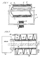
- a continuous flow induction heater is illustrated.
- a motor 21 rotates a screw structure 22.
- the screw structure 22 comprises an outerwall 23 which has a spiral slot cut in it to receive screw flight 24.
- the structure 22 also has an inner wall 25.
- Atoroidal ferromagnetic core 26 is sandwiched between the inner and outer walls 23 and 25.
- the toroidal core is formed of several individual ring cores with stiffening ribs 27 disposed between adjacent rings.
- An electrically conducting conductor 1, corresponding to that shown in Figure 1, runs along the axis of the structure 22. Thus, when alternating electrical current passes through conductor 1 magnetic flux is induced in the toroidal rings 26.
- the inner and outerwalls 23 and 25 are arranged to form an electrically conducting closed loop around the toroidal cores 26 so that induced magnetic flux in the cores also induces electrical currents to flow in the walls 23 and 25 and the screw flight 24.
- the structure 22 is located within a can 28 having an inlet 29 and an outlet 30 as shown. Consequently, material entering at 29 contacts the structure and is urged towards outlet 30 by the screw flight 24 when the motor 21 rotates the structure 22 in the direction of the arrow A.
- Figure 2 illustrates a continuous flow induction heater having a heated screw flight.
- the heating of the flight and the supply of heat to the walls 23 and 25 is provided without complex rotary couplings.
- the heaters shown in Figures 1 and 2 are merely examples of induction heaters embodying the invention.
- the rotary device shown in Figure 2 could be applied to an extruder.
- the induction heater embodying the invention can be used to mix materials and heat them at the same time and has the advantage of providing a high heat transfer area between the heating element of the heater and the material to be heated.
- the maximum operating temperature of the heater is limited by the Curie temperature of the iron core. With the designs illustrated the inner and outer skins and the core tend in time to reach approximately the same temperature.
- Figure 3 illustrates an example of a modification which can allow the hot elements of the heater to operate at temperatures above the temperature of the magnetic core.
- the modification is shown as applied to the embodiment described above with respect to Figure 1.
- the outer cylinder of the electrically conducting closed loop is formed to have an electrical resistance in the direction of the axis which is less than that of the inner cylinder 5 with fins 3.
- the outer cylinder is formed in this example of a copper cylinder 40 which is fastened at each end by means of bolts 41 to a copper mounting ring 42.
- the mounting ring 42 is secured, e.g. by electron beam welding to the associated annular end plate 6 or 9.
- the inner cylinder 5 and fins 3 are made of a metal having the necessary mechanical strength and heat resistant qualities and also having an electrical resistivity such that the resistance along the axis of the combined inner cylinder 5 and fins 3 is higher, preferably substantially higher than the resistance of the copper cylinder 40.
- the inner cylinder 5 and fins 3 may be made of steel for example.
- the outer cylinder 40 may be cooler than the inner cylinder 5, permitting a temperature gradientto be established between the inner and outer cylinders.
- the magnetic core 43 located between the inner and outer cylinder may thus be maintained at a temperature below that of the inner cylinder 5.
- a thermal insulation 44 is provided between the inner cylinder 5 and the magnetic core 43 to maximise the temperature difference between the inner cylinder 5 and the core.
- the outer copper cylinder 40 may be perforated to permit air ventilation of the magnetic core 43.
- An additional outer cylindrical casing 45 may be provided interconnecting the annular end plates 6 and 9 to provide additional mechanical rigidity and strength to the structure.
- the outer casing 45 may then also be perforated to permit passage of ventilating air to cool the core 43.
- the inner wall 25 would be made with an axial resistance lower than that of the outer wall 23 with screw flight 24, and thermal insulation would be provided between the outer wall 23 and the magnetic core 26. Ventilating air would be passed through the interior of the inner wall 25, which might be perforated, to cool the magnetic core.
Abstract
Description
- This invention relates to an induction heater wherein material is heated by contact with an inductively heated heating element.
- Bulk or continuous flow heaters are employed as dryers or calciners. Typically, a heating member contacts material to be heated so that heat is efficiently transferred from the heating element to the material to be heated.
- FR-A-2339315 discloses an induction heater comprising a wire wound on a toroidal primary core, the core being arranged around a cylindrical heating element having a cavity for holding the material to be heated. Conductive elements join the top and bottom of the cylinder to provide a circuit for the induced currents. Some degree of mixing action to improve contact can also be incorporated with the heating action of the heating element, for example by providing the heating element with fin members, as a result contact between the heating element and the material to be heated is enhanced. However, it is preferable to provide substantially uniform heating of the material to be heated. Consequently, means are required to supply heat uniformly to the heating member and the fin members thereof. Reference may be made, for example, to "Industrial Furnaces" by W. Trinks, published by John Wiley (1963).
- The supply of heat to the heating element is particularly problematical where fin members are included. Known dryers incorporate heating by means of gas jets or hot fluid. Consequently, in order to heat such fin members complicated supply tubing must be engineered into the fin member. It is also known to adapt the fin member to enhance the mixing resulting from movement of the heating element. This only serves to further complicate the design of the fin member. Particular problems are encountered with rotary drum dryers and calciners since it is necessary to incorporate rotary couplings for supply of the hot fluid or gases. Consequently, there are a number of drawbacks for heating the heating element of known bulk or continuous flow heaters.
- According to this invention there is provided an induction heater comprising an alternating current carrying conductor extending along an axis; a core means substantially encircling said axis to guide magnetic flux resulting from said alternating current; an electrically conducting closed loop encircling magnetic flux in the core means and comprising a heating element for contacting and transferring heat to material to be heated, the heating element being heated by electrical current induced in said closed loop, and being adapted to effect relative movement (A) between material in contact therewith and said axis.
- In the heater of the invention the heating element is remotely heated by induced electrical currents produced from the magnetic flux flowing in the core means. There is then no requirement to provide mechanical coupling between the heat energy source and the heating element.
- The heater can effect said relative movement by causing the heating element to be moved periodically along or about said axis, or alternatively by causing the heating element to vibrate. Since the heating element is inductively heated, the provision for effecting relative movement does not further complicate supply of heat to the heating element.
- Conveniently, the heating element includes at least one fin member whereby the surface area capable of contacting the material to be heated is increased. The fin member forms part of the electrically conducting closed loop encircling the magnetic flux and therefore some electrical current is induced in the fin member to heat it. It can therefore be seen that supply of heat specifically to the fin member is considerably simplified compared with the above mentioned bulk or continuous flow heaters.
- In a preferred embodiment, a part of said loop formed by the heating element has an electrical resistance per unit length in the direction around the loop encircling the flux, which is higher than the resistance of the remainder of the loop. With this arrangement, a major part of the resistive heating of the heating element loop can take place at said higher resistance part, allowing a temperature gradient to be set up between this part and the remainder of the loop. As a result the magnetic core means located in the loop between the higher resistance part and the remainder, can be at a temperature below that of the high resistance part.
- Preferably, heat insulating means is provided between said higher resistance part of the loop and the core means. Also, cooling means may be provided in or adjacent said remainder of the loop.
- The invention will now be described by way of example with reference to the drawings, in which:
- Figure 1 illustrates a bulk induction heater embodying the invention;
- Figure 2 illustrates a continuous flow induction heater embodying the invention; and
- Figure 3 is a part axial cross-section of a modified version of the Figure 1 embodiment.
- Referring to Figure 1, a current carrying conductor 1 is shaped as a loop to pass through a primary transformer 8 at a convenient point. The conductor is typically made of copper and may be laminated to reduce the AC resistance. A portion of the conductor 1 forms an axis about which is provided a
ferromagnetic core 4. Thecore 4 is enclosed within a metal skin formed from concentrically alignedinner cylinder 5 and outer cylinder 7 andend plates 6 and 9. In this way, the skin forms a closed electrically conducting loop about thecore 4. Thecore 4 is typically formed from a laminated ferromagnetic material. - Alternating current set up in the conductor 1 by the toroidally wound transformer 8 sets up an alternating magnetic flux which is guided by the
core 4. In turn, the alternating flux incore 4 induces currents to flow around the above mentioned electrically conducting closed loop. These currents flow in the direction of the axes of thecylinders 5 and 7. - Consequently, material to be heated can be placed within the
inner cylinder 5 and be heated by the energy produced in the cylinder by the induced axial currents. To enhance contact between the material to be heated and thecylinder 5,fins 3 are provided on the axially facing side of thecylinder 5. It will be apparent that a suitable protective tube may be required to protect the conductor 1. The structure comprising thecylinders 5 and 7 andcore 4 can be rotated in the direction of the arrow A. In this way, the material to be heated is moved into and out of contact with thecylinder 5 to allow uniform transfer of heat from the cylinder to the material to be heated. Heating thefin members 3 is advantageous because the material is in contact with a large heated surface area and is continually agitated or mixed. Such a heater can be employed as a bulk heater or can be tilted so that material gravitates towards one or other of theend plates 6 and 9 as the structure 2 is rotated. This form of heater has particular advantages when high air flows through the heater are undesirable for example when drying fine powders. - It will be apparent that by suitable arrangement of the induced currents flowing in the skin of the structure 2 high temperatures can be achieved, for example up to the Curie temperature of the core, whilst at the same time maintaining a high surface contact area. This has particular uses in calciners.
- Referring to Figure 2, a continuous flow induction heater is illustrated. A
motor 21 rotates ascrew structure 22. Thescrew structure 22 comprises anouterwall 23 which has a spiral slot cut in it to receivescrew flight 24. Thestructure 22 also has aninner wall 25. Atoroidalferromagnetic core 26 is sandwiched between the inner andouter walls stiffening ribs 27 disposed between adjacent rings. An electrically conducting conductor 1, corresponding to that shown in Figure 1, runs along the axis of thestructure 22. Thus, when alternating electrical current passes through conductor 1 magnetic flux is induced in thetoroidal rings 26. The inner andouterwalls toroidal cores 26 so that induced magnetic flux in the cores also induces electrical currents to flow in thewalls screw flight 24. Thestructure 22 is located within acan 28 having aninlet 29 and anoutlet 30 as shown. Consequently, material entering at 29 contacts the structure and is urged towardsoutlet 30 by thescrew flight 24 when themotor 21 rotates thestructure 22 in the direction of the arrow A. - Thus, Figure 2 illustrates a continuous flow induction heater having a heated screw flight. The heating of the flight and the supply of heat to the
walls - It will be apparent that the heaters shown in Figures 1 and 2 are merely examples of induction heaters embodying the invention. For example, the rotary device shown in Figure 2 could be applied to an extruder. The induction heater embodying the invention can be used to mix materials and heat them at the same time and has the advantage of providing a high heat transfer area between the heating element of the heater and the material to be heated.
- The maximum operating temperature of the heater is limited by the Curie temperature of the iron core. With the designs illustrated the inner and outer skins and the core tend in time to reach approximately the same temperature. Figure 3 illustrates an example of a modification which can allow the hot elements of the heater to operate at temperatures above the temperature of the magnetic core.
- In Figure 3, the modification is shown as applied to the embodiment described above with respect to Figure 1. The outer cylinder of the electrically conducting closed loop is formed to have an electrical resistance in the direction of the axis which is less than that of the
inner cylinder 5 withfins 3. Thus, the outer cylinder is formed in this example of acopper cylinder 40 which is fastened at each end by means of bolts 41 to acopper mounting ring 42. The mountingring 42 is secured, e.g. by electron beam welding to the associatedannular end plate 6 or 9. - The
inner cylinder 5 andfins 3 are made of a metal having the necessary mechanical strength and heat resistant qualities and also having an electrical resistivity such that the resistance along the axis of the combinedinner cylinder 5 andfins 3 is higher, preferably substantially higher than the resistance of thecopper cylinder 40. Theinner cylinder 5 andfins 3 may be made of steel for example. - Because of the higher resistance of the
inner cylinder 5 andfins 3, most of the heating energy is delivered to theinner cylinder 5 andfins 3 rather than the copperouter cylinder 40. As a result theouter cylinder 40 may be cooler than theinner cylinder 5, permitting a temperature gradientto be established between the inner and outer cylinders. The magnetic core 43 located between the inner and outer cylinder may thus be maintained at a temperature below that of theinner cylinder 5. - Preferably, a
thermal insulation 44 is provided between theinner cylinder 5 and the magnetic core 43 to maximise the temperature difference between theinner cylinder 5 and the core. Further, theouter copper cylinder 40 may be perforated to permit air ventilation of the magnetic core 43. - An additional outer
cylindrical casing 45, typically of steel, may be provided interconnecting theannular end plates 6 and 9 to provide additional mechanical rigidity and strength to the structure. Theouter casing 45 may then also be perforated to permit passage of ventilating air to cool the core 43. - It will be appreciated that the above preferred construction may also be applied to other embodiments of the invention such as that illustrated in Figure 2. In Figure 2, the
inner wall 25 would be made with an axial resistance lower than that of theouter wall 23 withscrew flight 24, and thermal insulation would be provided between theouter wall 23 and themagnetic core 26. Ventilating air would be passed through the interior of theinner wall 25, which might be perforated, to cool the magnetic core.
Claims (10)
Priority Applications (1)
| Application Number | Priority Date | Filing Date | Title |
|---|---|---|---|
| AT85305673T ATE59522T1 (en) | 1984-08-28 | 1985-08-09 | INDUCTION HEATER. |
Applications Claiming Priority (2)
| Application Number | Priority Date | Filing Date | Title |
|---|---|---|---|
| GB848421762A GB8421762D0 (en) | 1984-08-28 | 1984-08-28 | Induction heater |
| GB8421762 | 1984-08-28 |
Publications (2)
| Publication Number | Publication Date |
|---|---|
| EP0175470A1 EP0175470A1 (en) | 1986-03-26 |
| EP0175470B1 true EP0175470B1 (en) | 1990-12-27 |
Family
ID=10565939
Family Applications (1)
| Application Number | Title | Priority Date | Filing Date |
|---|---|---|---|
| EP85305673A Expired - Lifetime EP0175470B1 (en) | 1984-08-28 | 1985-08-09 | Induction heater |
Country Status (5)
| Country | Link |
|---|---|
| US (1) | US4629844A (en) |
| EP (1) | EP0175470B1 (en) |
| AT (1) | ATE59522T1 (en) |
| DE (1) | DE3581147D1 (en) |
| GB (2) | GB8421762D0 (en) |
Families Citing this family (13)
| Publication number | Priority date | Publication date | Assignee | Title |
|---|---|---|---|---|
| FR2600759B1 (en) * | 1986-06-30 | 1989-07-13 | Electricite De France | CONTINUOUS PROCESSING OVEN FOR PULVERULENT, GRANULOUS OR PASTY MATERIAL |
| GB2205720B (en) * | 1987-06-10 | 1991-01-02 | Electricity Council | Induction heater |
| GB2247141B (en) * | 1990-08-13 | 1994-05-18 | Electricity Ass Services Ltd | Induction heater |
| GB2262693B (en) * | 1991-12-17 | 1995-06-07 | Electricity Ass Tech | Induction heater |
| US5786575A (en) * | 1995-12-20 | 1998-07-28 | Gas Research Institute | Wrap tool for magnetic field-responsive heat-fusible pipe couplings |
| DE19921320C2 (en) * | 1998-05-12 | 2002-10-17 | Usui Kokusai Sangyo Kk | magnet type heater |
| JP3982656B2 (en) * | 1998-05-19 | 2007-09-26 | 臼井国際産業株式会社 | Magnetic heater |
| US6209225B1 (en) * | 1998-10-23 | 2001-04-03 | Danilo Villarroel | Rotatoty dryer for copper concentrate |
| DE19858137B4 (en) * | 1998-12-16 | 2016-12-15 | BSH Hausgeräte GmbH | Heating for heating the rinsing liquid in a dishwasher |
| FR2841475B1 (en) * | 2002-06-28 | 2005-01-14 | Deschamps Lathus Sa | METHOD OF THERMAL TREATMENT BY INDUCTION OF A SANITARY WATER PIPING AND SYSTEM FOR ITS IMPLEMENTATION |
| ITUB20155969A1 (en) * | 2015-11-27 | 2017-05-27 | Fernando Bressan | HEATED EXTRUDER FOR PLASTIC MATERIALS |
| US11336150B2 (en) * | 2017-01-24 | 2022-05-17 | Sumitomo Electric Industries, Ltd. | Energy storage system and system enabling stable utilization of variable electric power |
| WO2021072148A1 (en) * | 2019-10-09 | 2021-04-15 | Heat X, LLC | Magnetic induction furnace, cooler or magnetocaloric fluid heat pump with varied conductive plate configurations |
Citations (2)
| Publication number | Priority date | Publication date | Assignee | Title |
|---|---|---|---|---|
| CH453490A (en) * | 1965-08-19 | 1968-06-14 | Bbc Brown Boveri & Cie | Device for measuring the current in a primary conductor |
| FR2152940A1 (en) * | 1971-09-10 | 1973-04-27 | Tracked Hovercraft Ltd |
Family Cites Families (15)
| Publication number | Priority date | Publication date | Assignee | Title |
|---|---|---|---|---|
| FR515457A (en) * | 1919-04-05 | 1921-04-02 | Oerlikon Maschf | Electric air heater |
| DE434567C (en) * | 1922-01-22 | 1926-09-24 | Otto Titus Blathy Dr | Device for heating circulating iron hollow rollers by means of electrical induction currents |
| FR606564A (en) * | 1925-02-23 | 1926-06-16 | New electric heater | |
| US2181274A (en) * | 1938-05-11 | 1939-11-28 | Utilities Coordinated Res Inc | Induction heater construction |
| US2904664A (en) * | 1957-09-25 | 1959-09-15 | Sealtron Corp | Magnetic heating in extrusion apparatus |
| US3154663A (en) * | 1959-01-30 | 1964-10-27 | Nat Scient Lab Inc | Apparatus and process for thawing temperature sensitive frozen materials |
| GB931298A (en) * | 1959-07-17 | 1963-07-17 | Blaw Knox Co | Eddy current induction heater |
| US3107268A (en) * | 1960-12-09 | 1963-10-15 | Du Pont | Melting furnace |
| GB1043002A (en) * | 1963-01-18 | 1966-09-21 | Allegemeinen Elek Citats Ges | A submerged-resistor type electric induction furnace |
| CH434550A (en) * | 1964-11-21 | 1967-04-30 | Tokushu Denki Kabushiki Kaisha | Electrically heated rotating heating drum |
| US4039794A (en) * | 1976-01-14 | 1977-08-02 | Park-Ohio Industries, Inc. | Apparatus and method for heating ferromagnetic abrasive shot |
| US4145591A (en) * | 1976-01-24 | 1979-03-20 | Nitto Chemical Industry Co., Ltd. | Induction heating apparatus with leakage flux reducing means |
| GB1557590A (en) * | 1976-10-25 | 1979-12-12 | Secr Defence | Gas thrusters |
| DE2731487A1 (en) * | 1977-07-12 | 1979-01-18 | Schuwerk | Heat exchanger system for heating fluids - has fluid flowing over metal tube containing heating resistance wire |
| US4238337A (en) * | 1979-02-09 | 1980-12-09 | Walter Todd Peters | Methane gas producer using biological decomposition of waste matter |
-
1984
- 1984-08-28 GB GB848421762A patent/GB8421762D0/en active Pending
-
1985
- 1985-08-09 DE DE8585305673T patent/DE3581147D1/en not_active Expired - Fee Related
- 1985-08-09 EP EP85305673A patent/EP0175470B1/en not_active Expired - Lifetime
- 1985-08-09 AT AT85305673T patent/ATE59522T1/en not_active IP Right Cessation
- 1985-08-09 GB GB08520031A patent/GB2163930B/en not_active Expired
- 1985-08-28 US US06/770,133 patent/US4629844A/en not_active Expired - Lifetime
Patent Citations (2)
| Publication number | Priority date | Publication date | Assignee | Title |
|---|---|---|---|---|
| CH453490A (en) * | 1965-08-19 | 1968-06-14 | Bbc Brown Boveri & Cie | Device for measuring the current in a primary conductor |
| FR2152940A1 (en) * | 1971-09-10 | 1973-04-27 | Tracked Hovercraft Ltd |
Also Published As
| Publication number | Publication date |
|---|---|
| ATE59522T1 (en) | 1991-01-15 |
| US4629844A (en) | 1986-12-16 |
| DE3581147D1 (en) | 1991-02-07 |
| GB8520031D0 (en) | 1985-09-18 |
| GB8421762D0 (en) | 1984-10-03 |
| GB2163930B (en) | 1987-05-07 |
| GB2163930A (en) | 1986-03-05 |
| EP0175470A1 (en) | 1986-03-26 |
Similar Documents
| Publication | Publication Date | Title |
|---|---|---|
| EP0175470B1 (en) | Induction heater | |
| US3307007A (en) | Electromagnetic heating unit | |
| US7424045B2 (en) | Method and apparatus for heating a workpiece in an inert atmosphere or in vacuum | |
| US5003145A (en) | Inductively operated heating apparatus for plastic materials | |
| US5274207A (en) | Induction heater | |
| BG60656B1 (en) | Device for fluid heating | |
| US5420401A (en) | Microwave oven, in particular for rapid heating to high temperature | |
| US1981632A (en) | Heating apparatus | |
| US5455402A (en) | Induction heater having a conductor with a radial heating element | |
| EP0295072B1 (en) | Induction heater | |
| CA2516737A1 (en) | Continuous extrusion apparatus | |
| US4960967A (en) | Device for protecting the poles of inductors and inductor equipped with such device | |
| JPS5653868A (en) | Heating device of ladle | |
| JP2003100426A (en) | Hot blast generator by induction heating | |
| US2308945A (en) | High-frequency induction furnace | |
| EP0484327A1 (en) | Arrangement for converting electrical energy to heat energy | |
| US5744784A (en) | Low-loss induction coil for heating and/or melting metallic materials | |
| US2937217A (en) | Electric furnace | |
| US2968685A (en) | Apparatus for electro-magnetic stirring | |
| JP2003173865A (en) | Object heating method | |
| JPS60229080A (en) | Toner fixing device | |
| JPH02108998A (en) | Heat-resisting driving coil and control rod driving device | |
| US1859419A (en) | Electric induction furnace | |
| SU1177004A1 (en) | Arrangement for moulding hollow parts with heating | |
| SU1082616A1 (en) | Plate for hot pressing |
Legal Events
| Date | Code | Title | Description |
|---|---|---|---|
| PUAI | Public reference made under article 153(3) epc to a published international application that has entered the european phase |
Free format text: ORIGINAL CODE: 0009012 |
|
| AK | Designated contracting states |
Kind code of ref document: A1 Designated state(s): AT BE CH DE FR GB IT LI LU NL SE |
|
| 17P | Request for examination filed |
Effective date: 19860526 |
|
| 17Q | First examination report despatched |
Effective date: 19880203 |
|
| RBV | Designated contracting states (corrected) |
Designated state(s): AT BE CH DE FR IT LI LU NL SE |
|
| GRAA | (expected) grant |
Free format text: ORIGINAL CODE: 0009210 |
|
| AK | Designated contracting states |
Kind code of ref document: B1 Designated state(s): AT BE CH DE FR IT LI LU NL SE |
|
| REF | Corresponds to: |
Ref document number: 59522 Country of ref document: AT Date of ref document: 19910115 Kind code of ref document: T |
|
| REF | Corresponds to: |
Ref document number: 3581147 Country of ref document: DE Date of ref document: 19910207 |
|
| ITF | It: translation for a ep patent filed |
Owner name: STUDIO TORTA SOCIETA' SEMPLICE |
|
| ET | Fr: translation filed | ||
| PLBE | No opposition filed within time limit |
Free format text: ORIGINAL CODE: 0009261 |
|
| STAA | Information on the status of an ep patent application or granted ep patent |
Free format text: STATUS: NO OPPOSITION FILED WITHIN TIME LIMIT |
|
| 26N | No opposition filed | ||
| PGFP | Annual fee paid to national office [announced via postgrant information from national office to epo] |
Ref country code: LU Payment date: 19920812 Year of fee payment: 8 |
|
| PGFP | Annual fee paid to national office [announced via postgrant information from national office to epo] |
Ref country code: AT Payment date: 19920828 Year of fee payment: 8 |
|
| EPTA | Lu: last paid annual fee | ||
| REG | Reference to a national code |
Ref country code: CH Ref legal event code: PUE Owner name: ELECTRICITY ASSOCIATION SERVICES LIMITED |
|
| PGFP | Annual fee paid to national office [announced via postgrant information from national office to epo] |
Ref country code: BE Payment date: 19930628 Year of fee payment: 9 |
|
| PG25 | Lapsed in a contracting state [announced via postgrant information from national office to epo] |
Ref country code: LU Free format text: LAPSE BECAUSE OF NON-PAYMENT OF DUE FEES Effective date: 19930809 Ref country code: AT Effective date: 19930809 |
|
| PGFP | Annual fee paid to national office [announced via postgrant information from national office to epo] |
Ref country code: CH Payment date: 19930812 Year of fee payment: 9 |
|
| PGFP | Annual fee paid to national office [announced via postgrant information from national office to epo] |
Ref country code: SE Payment date: 19930817 Year of fee payment: 9 |
|
| ITTA | It: last paid annual fee | ||
| REG | Reference to a national code |
Ref country code: FR Ref legal event code: TP |
|
| ITPR | It: changes in ownership of a european patent |
Owner name: CESSIONE;ELECTRICITY ASSOCIATION SERVICES LIMITED |
|
| NLS | Nl: assignments of ep-patents |
Owner name: ELECTRICITY ASSOCIATION SERVICES LIMITED TE LONDEN |
|
| PG25 | Lapsed in a contracting state [announced via postgrant information from national office to epo] |
Ref country code: SE Effective date: 19940810 |
|
| PG25 | Lapsed in a contracting state [announced via postgrant information from national office to epo] |
Ref country code: LI Effective date: 19940831 Ref country code: CH Effective date: 19940831 Ref country code: BE Effective date: 19940831 |
|
| PGFP | Annual fee paid to national office [announced via postgrant information from national office to epo] |
Ref country code: NL Payment date: 19940831 Year of fee payment: 10 |
|
| REG | Reference to a national code |
Ref country code: FR Ref legal event code: TP |
|
| NLS | Nl: assignments of ep-patents |
Owner name: EA TECHNOLOGY LIMITED TE CAPENHURST, GROOT-BRITTAN |
|
| EAL | Se: european patent in force in sweden |
Ref document number: 85305673.7 |
|
| BERE | Be: lapsed |
Owner name: EA TECHNOLOGY LTS Effective date: 19940831 |
|
| REG | Reference to a national code |
Ref country code: CH Ref legal event code: PL |
|
| EUG | Se: european patent has lapsed |
Ref document number: 85305673.7 |
|
| ITPR | It: changes in ownership of a european patent |
Owner name: CESSIONE;EA TECHNOLOGY LIMITED |
|
| PG25 | Lapsed in a contracting state [announced via postgrant information from national office to epo] |
Ref country code: NL Effective date: 19960301 |
|
| NLV4 | Nl: lapsed or anulled due to non-payment of the annual fee |
Effective date: 19960301 |
|
| PGFP | Annual fee paid to national office [announced via postgrant information from national office to epo] |
Ref country code: DE Payment date: 20000630 Year of fee payment: 16 |
|
| PGFP | Annual fee paid to national office [announced via postgrant information from national office to epo] |
Ref country code: FR Payment date: 20000726 Year of fee payment: 16 |
|
| PG25 | Lapsed in a contracting state [announced via postgrant information from national office to epo] |
Ref country code: FR Free format text: LAPSE BECAUSE OF NON-PAYMENT OF DUE FEES Effective date: 20020430 |
|
| PG25 | Lapsed in a contracting state [announced via postgrant information from national office to epo] |
Ref country code: DE Free format text: LAPSE BECAUSE OF NON-PAYMENT OF DUE FEES Effective date: 20020501 |
|
| REG | Reference to a national code |
Ref country code: FR Ref legal event code: ST |