EP0175140A1 - Spent fuel storage cask having continuous grid basket assembly - Google Patents
Spent fuel storage cask having continuous grid basket assembly Download PDFInfo
- Publication number
- EP0175140A1 EP0175140A1 EP85110120A EP85110120A EP0175140A1 EP 0175140 A1 EP0175140 A1 EP 0175140A1 EP 85110120 A EP85110120 A EP 85110120A EP 85110120 A EP85110120 A EP 85110120A EP 0175140 A1 EP0175140 A1 EP 0175140A1
- Authority
- EP
- European Patent Office
- Prior art keywords
- cask
- fuel
- floor
- portions
- basket assembly
- Prior art date
- Legal status (The legal status is an assumption and is not a legal conclusion. Google has not performed a legal analysis and makes no representation as to the accuracy of the status listed.)
- Granted
Links
Images


Classifications
-
- G—PHYSICS
- G21—NUCLEAR PHYSICS; NUCLEAR ENGINEERING
- G21C—NUCLEAR REACTORS
- G21C19/00—Arrangements for treating, for handling, or for facilitating the handling of, fuel or other materials which are used within the reactor, e.g. within its pressure vessel
- G21C19/40—Arrangements for preventing occurrence of critical conditions, e.g. during storage
-
- G—PHYSICS
- G21—NUCLEAR PHYSICS; NUCLEAR ENGINEERING
- G21F—PROTECTION AGAINST X-RADIATION, GAMMA RADIATION, CORPUSCULAR RADIATION OR PARTICLE BOMBARDMENT; TREATING RADIOACTIVELY CONTAMINATED MATERIAL; DECONTAMINATION ARRANGEMENTS THEREFOR
- G21F5/00—Transportable or portable shielded containers
- G21F5/005—Containers for solid radioactive wastes, e.g. for ultimate disposal
- G21F5/008—Containers for fuel elements
- G21F5/012—Fuel element racks in the containers
-
- Y—GENERAL TAGGING OF NEW TECHNOLOGICAL DEVELOPMENTS; GENERAL TAGGING OF CROSS-SECTIONAL TECHNOLOGIES SPANNING OVER SEVERAL SECTIONS OF THE IPC; TECHNICAL SUBJECTS COVERED BY FORMER USPC CROSS-REFERENCE ART COLLECTIONS [XRACs] AND DIGESTS
- Y02—TECHNOLOGIES OR APPLICATIONS FOR MITIGATION OR ADAPTATION AGAINST CLIMATE CHANGE
- Y02E—REDUCTION OF GREENHOUSE GAS [GHG] EMISSIONS, RELATED TO ENERGY GENERATION, TRANSMISSION OR DISTRIBUTION
- Y02E30/00—Energy generation of nuclear origin
- Y02E30/30—Nuclear fission reactors
Definitions
- the present invention is related to the long-term storage of spent fuel that has been removed from a nuclear reactor, and more particularly, to a spent fuel storage cask having a continuous grid basket assembly which supports the spent fuel and which dissipates heat generated by the spent fuel.
- the requirements which must be imposed on such a cask are rather severe.
- the cask must be immune from chemical attack during long-term storage. Furthermore, it must be sufficiently rugged mechanically to avoid even tiny ruptures or fractures during long-term storage and during transportation, when the cask might be subjected to rough treatment or accidents such as drops.
- the cask must be able to transmit heat generated by the spent fuel to the environment while nevertheless shielding the environment from radiation generated by the spent fuel.
- the temperature of the spent fuel rods must be kept below a maximum temperature, such as 375°C, to prevent deterioration of the zirconium alloy housing. Provisions must also be made to ensure that a chain reaction cannot be sustained within the cask; that is, that the effective criticality factor K eff remains less than one so that a self-sustaining reaction does not occur.
- the present invention resides in a cask for long-term storage of spent nuclear fuel comprising: a container having a cavity therein, the cavity including a top portion, a bottom portion defining a floor, and side walls extending between the top and bottom portions; characterized in that a grid basket assembly is disposed within the cavity, said grid basket assembly including a plurality of metal plates joined together to provide a matrix of storage slots for accommodating the spent fuel, and means are provided for transferring heat from said grid basket assembly to said side walls while permitting movement of said grid basket assembly with respect to said side walls in response to temperature changes.
- At least some of the walls of the cells include sheets of boron carbide or other "neutron poison" supported by wrapper elements, which may include apertures to permit visual confirmation that neutron poison is present and to facilitate drainage of borated water when spent fuel is being loaded into the cask.
- a consolidation canister containing fuel rods instead of a cell for receiving a fuel assembly, may be deposited in a storage slot if the slot is to be used for storage of fuel in consolidated form.
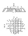
- FIG. 1 illustrates a typical fuel assembly 20 for supplying nuclear fuel to a reactor.
- Assembly 20 includes a bottom nozzle 22 and a top nozzle 24, between which are disposed elongated fuel rods 26.
- Each fuel rod 26 includes a cylindrical housing made of a zirconium alloy such as commercially available "Zircaloy-4", and is filled with pellets of fissionable fuel enriched with U-235.
- tubular guides (not shown) are disposed between nozzles 22 and 24 to accommodate movably mounted control rods (not illustrated) and measuring instruments (not illustrated). The ends of these tubular guides are attached to nozzles 22 and 24 to form a skeletal support for fuel rods 26, which are not permanently attached to nozzles 22 and 24.
- Grid members 28 have apertures through which fuel rods 26 and the tubular guides extend to bundle these elements together.
- Commercially available fuel assemblies for pressurized water reactors include between 179 and 264 fuel rods, depending upon the particular design.
- a typical fuel assembly is about 4.1 meters long, about 19.7 cm wide, and has a mass of about 585 kg., but it will be understood that the precise dimensions vary from one fuel assembly design to another.
- Pool 30 is typically 12.2 meters deep.
- a number of spent fuel racks 32 positioned at the bottom of pool 30 are provided with storage slots 34 to vertically accommodate fuel assemblies 20.
- a cask pad 36 is located at the bottom of pool 30.
- Dry storage casks provide one form of long-term storage for the spent fuel. After the heat generated by each fuel assembly 20 falls to a predetermined amount -such as 0.5 to 1.0 kilowatt per assembly, after perhaps 10 years of storage in pool 30 -- an opened cask is lowered to pad 36. By remote control the spent fuel is transferred to the cask, which is then sealed and drained of borated water. The cask can then be removed from pool 30 and transported to an above-ground storage area for long-term storage.
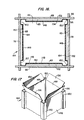
- the cask 38 of the present invention includes a generally cylindrical container 40 having a grid basket assembly 42 disposed therein.
- Grid basket assembly 42 provides an array of storage slots 44, configured much like a matrix of vertically disposed pigeonholes, each accommodating a cell 46.
- the fuel assemblies 20 are placed in the cells 46 for storage.
- container 40 includes a base element 48 having an upper portion configured to receive lid element 50.
- the cavity 51 provided within base element 48 has substantially cylindrical walls 53 rising from floor 55, which is substantially horizontal during long-term storage.
- Elements 48 and 50 include carbon steel portions 52 to which intercladding layers 54 of stainless steel are affixed. Carbon steel portions 52 are approximately 25 cm thick and serve to protect the environment from gamma rays.
- Layer 54 can be applied to base element 48, for example, by placing it on a turntable and rotating it while welding a continuous spiral path around the interior using stainless steel welding rods, thereby applying a stainless steel surface which completely covers the floor 55 and side walls 53 of element 48.
- elements 48 and 50 are provided with a layer about 7.0 cm thick of neutron absorbing material 56, which may be a resin.
- a suitable resin for use as material 56 is commercially available from Bisco Products, Inc., 1420 Renaissance Drive, Park Ridge, Illinois 60068, under Stock No. N.S.-3.
- Surrounding material 56 is outer layer 58 of stainless steel to protect cask 38 from the environment.
- Cask 38 also includes cooling fins 60 of carbon steel, preferably treated to protect the carbon steel from chemical attack by the environment. Fins 60 are welded to portion 52 and extend through material 56 and layer 58.
- cask 38 is approximately 4.8 meters high and has an outer diameter of about 2.5 meters, excluding fins 60. When loaded with spent fuel, cask 38 has a mass of over a hundred thousand kilograms.
- grid basket assembly 42 includes major plates 62, 64, 66, 68, 70, 72, 74, 76, 78 and 80. These plates may be fabricated of aluminum sheets approximately 3.7 meters high and 2.0 cm thick.
- the bottom portion of plate 66 for example, includes five downwardly oriented slots 82 dividing the bottom portion of plate 66 into six segments, each of these six segments forming a portion of one of the four walls 83 ( Figure 3) of a storage slot 44.
- the upper portion of plate 76 for example, includes five upwardly extending slots 84.
- the slots 82 in plate 66 and the slots 84 in plate 76 are about 26.3 cm apart, and it will be apparent that such dimensions provide slots 44 which are positioned about 26.3 cm apart, center-to-center.
- plates 62, 64, 66, 68 and 70 are held at right angles to plates 72, 74, 76, 78 and 80, and the slots 82 are then inserted into slots 84-to provide intersections which run the entire length of the plates.
- the plates are joined by full length fillet welds along opposite sides of the intersections, so that there are two welds running along each intersection. This is best illustrated in Figure 5 where, for example, welds 86 are oppositely disposed along the intersection formed by plates 68 and 78.
- minor plates 88 are welded at one end of plate 66 and minor plates 90 are welded at the other end.
- minor plates 92 are welded at one end of plate 76 and minor plates 94 are welded at the other end.
- Minor plate 96 is welded at the intersection of plates 62 and 72
- minor plate 98 is welded at the intersection of plates 62 and 80
- minor plate 100 is welded at the intersection of plates 80 and 70
- minor plate 102 is welded at the intersection of plates 70 and 72.
- Minor plates 103 are welded to plates 64, 68, 74 and 78.
- tabs 104 are welded to the plates adjacent the intersections.
- Panel portions 106 of stainless steel about .25 cm thick, are bent to provide cell walls 107 and flanges 108, which slidably extend between tabs 104.
- walls 107 contact the sides of fuel assembly 20 to keep it positioned at a predetermined location in slot 44 in order to maintain the spacing between fuel assemblies 20.
- fuel assemblies are positioned centrally within slots 44 and, for the sake of convenience, it will be said that they are "centered" therein by walls 107, although it will be understood that this does not exclude other uniform positioning patterns.
- the sheets 112 and the spacing limit the nuclear interaction between fuel assemblies 20, which are of course designed to promote chain reactions when they are present in a reactor. It is worth noting that sheets 112 have served their purpose after the borated water has been drained from cask 38 during the loading process, since thereafter the potential for a chain reaction is reduced.
- the foregoing details concerning the thickness of the stainless steel elements and the neutron poison are characteristic of the remaining cell embodiments disclosed herein and need not be repeated.
- holes 114 can be provided in portions 110 in order to permit visual confirmation that sheets 112 are present and to facilitate the escape of borated water when cask 38 is drained. During drainage the temperature within cask 38 rises to the boiling temperature of the borated water, so that a prolonged drying time is not required.
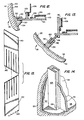
- panel portions 106 include projections 116 which extend beyond grid basket assembly 42 when portions 106 are installed.
- the projections 116 are bent to provide flanges 118.
- brace elements 12.0 are welded to the projections 116 in order to support the portion of cell 46 that extend beyond grid basket assembly 42. It will be apparent from Figure 7 that flanges 118 provide a funnel to guide fuel assemblies 20 into the cell 46 as cask 38 is being loaded.
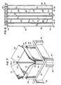
- Figure 8 illustrates cells 46 installed in grid basket assembly 42.
- Cells 46 are mechanically attached to grid basket assembly 42 only at lower portion 122 of assembly 42, so that the upper portions of assembly 42 and cells 46 may move with respect to each other in order to accommodate differences in the thermal coefficients of expansion between cells 46 and assembly 42. Differential expansion between grid 42 and cells 46 may amount two or more centimeters within the range of temperatures encountered during operation of cask 38. It will be noted from Figure 8 that panel portions 106, without poison sheets 112 and wrapper portions 110, provide one wall of each of the two cells 46 between plates 74, 78 and 62.
- the reason for this is that the cell walls lie at the periphery of assembly 42 and consequently neutrons that are generated within these cells and that travel directly to container 40 need not be moderated in order to avoid a critical mass.
- the outer wall of the cells 46 bounded by plates 64, 68 and 72, the outer walls of the cells 46 bounded by plates 74, 78 and 70, and the outer walls of the cells 46 bounded by plates 64, 68 and 80, can be provided by panel portions 106 without wrapper portions 110 and sheets 112 of neutron poison.
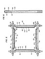
- FIG 10 illustrates grid basket assembly 42, having cells 46 installed therein in order to provide storage slots 44 for receiving fuel assemblies 20, mounted within cask 38.
- cask 38 and grid basket assembly 42 are fabricated separately.
- Cells 46 are installed in grid basket assembly 42 (except for the eight cell walls at the periphery of assembly 42 which are formed by panel portions 106 alone, without portions 110 or sheets 112) and, before assembly 42 is inserted within cask 38, stainless steel channel sections (which will be described below) are fitted to the projecting ends of plates 64, 66, 68, 74, 76, 78 and 96, 98, 100 and 102.
- an elongated channel section 124 is attached via full length fillet welds 126 to the wall 53 of cask 38.
- Channel section 124 has a generally U-shaped channel 128 which is slightly wider than the thickness of plate 66, thereby providing narrow gaps 130, which are perhaps .025-.05 cm wide if the gaps 130 are equal on each side. However, gaps 130 need not be symmetrical, and no adverse consequences arise if plate 66 contacts one side of channel 128.
- an inert gas such as helium, which transmits heat well through narrow gaps. However, other inert gases such as nitrogen can be used and, moreover, cask performance is acceptable with air.
- Figure 12 illustrates an elongated channel section 134 welded to the inner wall 53 of cask 38 in order to accommodate an edge of plate 64
- Figure 13 illustrates an elongated channel section 136 welded to the inner wall 53 of cask 38 in order to accommodate plate 96.
- there are narrow gaps 130 between the plates and the channel sections these narrow gaps producing little hindrance to heat transfer, particularly in a helium atmosphere, and spaces 132 to accommodate differential expansion of the elements.
- Figure 14 illustrates the lower portion 138 of channel section 124 as being solid in order to elevate plate 66.
- the lower portions of the remaining channel sections are, of course, configured in a similar manner.
- the plates of grid basket assembly 42 may be provided with drainage cut-outs.
- Figure 15 illustrates plates 140 and 142, corresponding to plates 66 and 76 of Figure 4, respectively, with drainage cut-outs 143.
- FIG. 16 and 17 A further cell embodiment is illustrated in Figures 16 and 17. Unlike the previous embodiment, the embodiment of Figures 16 and 17 does not require tabs 104. This is advantageous because the usable space in the storage slot 44 is effectively enlarged, so that the same grid basket assembly 42 which is used for storage of fuel assemblies 20 can, alternatively, be employed to store fuel in consolidated form. Use of cask 38 for consolidated storage will be discussed subsequently.
- cell 144 includes a hollow stainless steel shell element 146 having wall portions 148 joined by corner portions 150.
- the particular fuel assembly to be stored in cell 144 determines the cross-sectional area defined by wall portions 148. Corner portions 150 contact grid assembly 42 adjacent the intersections of the plates thereof.
- Four stainless wrapper portions 152 are welded'to shell element 146 between corner portions 150 in order to support neutron poison sheets 154. If desired, wrapper portions 152 may have openings to facilitate drainage of borated water and to permit verification that sheets 154 are present.
- brace elements 120 are unnecessary in order to support the portion of cell 144 that extends above grid assembly 42, since support in this region is provided by corner portions 150.
- the upper ends of wall portions 148 are bent outward to provide flanges 156 to act as funnels for guiding a fuel assembly 26 into the cell.
- the cells 144 can be attached to grid assembly 42 at bottom end 122 thereof in order to permit differential expansion of the cells 144 with respect to assembly 42 at different temperatures.
- cells which can readily be installed in cask 38 after it is fabricated, or removed from cask 38 after storage of fuel assemblies 20 so that cask 38 can be prepared to receive fuel in consolidated form will be deeded "removable" cells. It will be apparent that cells 144 are removable cells, unless they are permanently installed in assembly 42 at the time of manufacture, since they can readily be slid into or out of storage slots 44.
- cell 158 includes a four-sided stainless steel shell element 160 whose upper end is provided with flanges 161 to funnel the fuel assembly 20 into the cell.
- Stainless steel wrapper portions 162 are welded to element 160 in order to support neutron poison sheets 166 between element 160 and portion 162.
- the spacer elements in this embodiment are provided by dimpled portions 168 in shell element 160 adjacent the upper end thereof and dimpled portions 170 positioned at various heights along wrapper portions 162.
- the bottom end of cell 158 can be bolted or welded to the lower end 122 of grid basket assembly 42 in the manner previously described or it may simply rest upon a support element as illustrated in Figures 22 and 23.
- a stainless steel support element 172 is provided with intersecting channels 173 to accommodate the bottoms of the plates of grid basket assembly 42.
- plates 66 and 76 are supported at their intersection, and it will be apparent that the other plate intersections are also provided with support.
- Elements 72 are welded to grid assembly 42 but not to the floor 55 of cask 38, thereby supporting grid 42 above the floor of cask 38 in order to facilitate the drainage of borated water from cask 38 when spent fuel is being loaded while nevertheless permitting differential expansion of cask 38 with respect to grid basket assembly 42.
- Support elements 172 are provided with flanges 174 against which the lower ends of cells 158 rest after they are inserted into storage slots 44 and with sloping walls 175 to center the cells and guide the lower ends towards flanges 174 as they are being inserted. In this way, dimpled portions 168, dimpled portions 170, and flanges 174 properly position the cells 158 within grid basket assembly 42 without bolting, welding, or clamping.
- Figure 20 is similar to that of Figures 18 .and 19 except that dimpled portions 168 are replaced by spacer members 176 that are welded to shell element 178. Although not illustrated in Figure 20, spacer members are also welded to stainless steel wrapper portions 179. The thickness of members 176 is, of course, greater than the thickness of the members welded to wrapper portions 178 so as to facilitate assembly of the cells into the grid basket assembly 42 while also providing lateral support of the cells.
- the removable cell embodiment of Figure 21 does not rest upon support elements 172 or upon floor 55. Instead, stainless steel spacer member 180 having a hooked portion 182 is welded to stainless steel shell element 184. Member 180 not only spaces the cell away from the slot walls 83, in the manner of member 176 in the embodiment of Figure 20, it also supports the cell adjacent the top thereof so that the cell hangs from the top rather than being supported from the bottom. It will be apparent that this arrangement, like the previous embodiments, accommodates differential expansion of the cell with respect to grid basket assembly 42. Although not illustrated in Figure 21, spacing members are also welded to stainless steel wrapper element 186, which supports sheet 188 of a neutron poison such as boron carbide.
- Figure 24 is a graph of the criticality or neutron multiplication K eff' assuming an anomalous condition, within a cask 38 that has been fully loaded with 24 fuel assemblies 20 following storage in pool 30 of borated water for approximately ten years, each of the fuel assemblies 20 having an array of 15 x 15 fuel rods 26.
- the anomalous condition which is assumed in Figure 24 is that fresh, or non-borated, water is introduced into cask 38.
- K eff is higher when fuel assemblies are stored than when fuel stored in consolidated form under conditions that are otherwise identical. The reason for this is that water slows or "thermalizes" neutrons, thereby increasing the probability of a fissionable reaction, and that fuel which is packed tightly effectively removes space which would otherwise be available for water. Accordingly K eff within cask 38 remains below .95 if some or all of the storage slots 44 are used for consolidated storage.
- the fuel rods 26 are removed from the fuel assemblies 20 and placed in a consolidation canister which holds a greater number of fuel rods than the number in a single fuel assembly.
- the nozzles 22 and 24, along with other non-fuel portions of the fuel assemblies 20, such as grid members 28, can then be stored separately in a low-level storage facility.
- FIG 25 illustrates a stainless steel consolidation canister which is filled with spent fuel.
- Canister 190 includes a base portion 192, a hollow body portion 194 having a collar 196 at the upper end thereof, and a lid portion 198 which is affixed by screws 200 to collar 196 in order to close canister 190.
- Bars 202 are welded to lid portion 198 to support rod 204.
- Rod 204 is present in order to accept a hook (not illustrated) for hoisting canister 190 into cask 38 after canister 190 is loaded with spent fuel. Both the loading and hoisting, of course, are accomplished by remote control.
- body portion 194 is provided with projections 206 which contact the walls of a storage slot 44 when canister 190 is inserted in cask 38 in order to provide lateral support for canister 190 within cask 38.
- Body portion 194 is also provided with openings 208 to permit passage of borated water.
- fuel rods 26 can be seen through openings 208.
- FIG. 27 illustrates the upper end of body portion 194 after it has been filled with the spent fuel rods 26 that have been removed from two fuel assemblies 20.
- Divider 210 is provided as part of body portion 194 and includes a stainless steel plate 212 having a flange 214 that is welded to one side of portion 194 and another plate 216 having a flange 218 that is welded to the other side of portion 194.
- a leg 220 terminating in a flange 222 that is welded to plate 216.
- leg 224 of plate 216 has a flange 226 which is welded to plate 212.
- the rods 26 from one fuel assembly 20 are inserted on one side of divider 210 and the rods 26 from another fuel assembly are inserted on the other side.
- Different fuel assembly designs have different numbers of rods, and divider 210 permits the canister 190 to be customized when it is manufactured in accordance with the design of the particular fuel assembly 20 whose rods 26 it will store. That is to say, it will be apparent that the space bounded by plate 212, leg 220, plate 216 and leg 224 can readily be adjusted during fabrication of canister 190 in order to provide a snug fit for the fuel rods 26 that canister 190 is to receive.
- threaded bores 228 through collar 196 of portion 194 are provided for receiving screws 200 (Figure 25) when lid portion 198 ( Figure 25) is attached.
- base portion 19 includes a foot plate 230 of stainless steel.
- the sides of plate 230 have hollowed regions 232 communicating with a passageway (not illustrated) through portion 192 in order to facilitate drainage of borated water from body portion 194.
- Plate 230 also has bevelled regions 234 at the bottom thereof.
- the bevelled regions 234 of plate 230 overlap flanges 174 of elements 172 and permit plate 230 to rest securely on floor 55 of cask 38, with edges 236 of plate 230 being nestled against sides 238 of elements 172.
- stainless steel support 240 is welded to plate 230.
- Support 240 is hollow and has walls which crumple in the event that canister 190 is accidentally dropped along its axis after it has been loaded with spent fuel; this crumpling absorbs energy which might otherwise rupture canister 190 during the accident.
- Stainless steel pedestal 242 is welded to support 240 and provides an outwardly extending rim 224 abutting the lower end of body portion 194.
- Platform portion 246 of pedestal 242 extends slightly into the. interior of body portion 192 and supports the lower ends of fuel rods 26.
- Portion 246 provides another way to customize canisters 190 to the fuel rods 26 of particular fuel assembly designs.
- platform portion 246 is manufactured to telescope further into body portion 194 if relatively short rods 26 are to be stored than if relatively long rods 26 are to be stored. Accordingly, it will be apparent to those skilled in the art that divider 210 and pedestal 242 permit canister 190 to be tailored during manufacture to the fuel rods of particular fuel assemblies 120.
- cask 38 need not be dedicated to either storage mode (that is, storage of intact fuel assemblies or storage of consolidated fuel) or to storage of spent fuel from any particular source (that is, spent fuel, either intact or consolidated, from any particular fuel assembly design). All that is necessary is that appropriately configured cells and/or consolidation canisters be present during the loading operation. Since both the cost and manufacturing lead time for cells and canisters are significantly less than for a storage cask, the versatility of cask 38 is expected to have considerable commercial significance.
- a cask 38 can simultaneously store both consolidated fuel and intact fuel assemblies. Moreover, the storage mode may be changed after storage has begun. For example, if a cask 38 originally stores 24 fuel assemblies 26, it can be returned to pool 30 and opened, the fuel rods 26 can be removed from the fuel assemblies 20 and placed in consolidation canisters 190, and the cask 38 can then be re-loaded with more spent fuel than it originally stored.
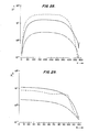
- Figures 28 and 29 indicate the effectiveness of cask 38 in isolating spent fuel from the environment.
- FIGs it is assumed that all 24 storage slots 44 in cask 38 have been loaded with fuel in consolidated form, each canister 190 housing 450 fuel rods 26 following storage thereof in borated water for approximately ten years.
- Figure 28 illustrates the dose rate, in milliroentgen/hour, along the exterior surface of the sides of cask 38 between adjacent fins 60. As can be seen in Figure 28, the dose rate D varies with the height H, in centimeters, above the bottom of the cask.
- the maximum neutron dose rate (solid curve) is less than 20 mrem/hr; the maximum primary gamma dose rate (that is, gamma rays from the interior of cask 38 which have passed through the cask walls) is less than 30 mrem/hr (dotted curve); and the maximum secondary gamma dose rate (gamma rays generated by neutron absorbing material 56 when neutrons are absorbed) is less than three mrem/hr (dot-dash curve). Accordingly, the maximum total dose rate at the side surface of cask 38 is less than 60 mrem/hr, and this dose rate falls rapidly with distance from the side surface.
- Figure 29 illustrates the dose rate D, in milliroentgen/hour, at the external surface of the bottom of cask 38.
- the bottom might be exposed, for example, during transportation of cask 38 to a remote storage location.
- R indicates the distance in centimeters along the bottom surface from the axis of cask 38 to the side walls, and it will be seen that D drops rapidly as the side walls are approached.
- the maximum neutron dose rate (solid curve) is less than 15 mrem/hr; the maximum primary gamma dose rate (dotted curve) is less than 10 mrem/hr; and the maximum secondary gamma dose rate (dot-dash curve) is less than 2 mrem/hr.
- the present invention provides a versatile and mechanically rugged spent fuel storage cask which reliably shields the environment from radiation produced by spent nuclear fuel stored therein despite temperature variations which arise during the loading of the fuel into the cask and long-term storage.
- Heat from fuel assemblies stored in the cells and/or fuel rods stored in consolidation canisters is transmitted by the grid assembly to channel sections affixed to the inner cask walls via narrow gaps between the U-shaped channels and the ends of the plates.
- the channel sections also provide space between the bottoms of the channels and the ends of the plates in order to accommodate radial movement of the grid basket assembly with respect to the cask as temperature changes.
- the various cell embodiments ensure that a sustained nuclear reaction cannot occur as fuel assemblies are loaded into the cask, and moreover, several cell embodiments are disclosed which permit ready conversion of the cask and grid basket assembly for the storage of consolidated fuel.
Abstract
Description
- The present invention is related to the long-term storage of spent fuel that has been removed from a nuclear reactor, and more particularly, to a spent fuel storage cask having a continuous grid basket assembly which supports the spent fuel and which dissipates heat generated by the spent fuel.
- The requirements which must be imposed on such a cask are rather severe. The cask must be immune from chemical attack during long-term storage. Furthermore, it must be sufficiently rugged mechanically to avoid even tiny ruptures or fractures during long-term storage and during transportation, when the cask might be subjected to rough treatment or accidents such as drops. Moreover, the cask must be able to transmit heat generated by the spent fuel to the environment while nevertheless shielding the environment from radiation generated by the spent fuel. The temperature of the spent fuel rods must be kept below a maximum temperature, such as 375°C, to prevent deterioration of the zirconium alloy housing. Provisions must also be made to ensure that a chain reaction cannot be sustained within the cask; that is, that the effective criticality factor Keff remains less than one so that a self-sustaining reaction does not occur.
- Accordingly, it is the principal object of the present invention to provide a mechanically rugged storage cask which prevents fission products and radiation from escaping into the environment while dissipating heat generated by spent fuel contained therein.
- With this object in view, the present invention resides in a cask for long-term storage of spent nuclear fuel comprising: a container having a cavity therein, the cavity including a top portion, a bottom portion defining a floor, and side walls extending between the top and bottom portions; characterized in that a grid basket assembly is disposed within the cavity, said grid basket assembly including a plurality of metal plates joined together to provide a matrix of storage slots for accommodating the spent fuel, and means are provided for transferring heat from said grid basket assembly to said side walls while permitting movement of said grid basket assembly with respect to said side walls in response to temperature changes.
- At least some of the walls of the cells include sheets of boron carbide or other "neutron poison" supported by wrapper elements, which may include apertures to permit visual confirmation that neutron poison is present and to facilitate drainage of borated water when spent fuel is being loaded into the cask. A consolidation canister containing fuel rods, instead of a cell for receiving a fuel assembly, may be deposited in a storage slot if the slot is to be used for storage of fuel in consolidated form.
- The invention will become more readily apparent from the following description of a preferred embodiment thereof shown, by way of example only, in the accompanying drawings, wherein:
- Figure 1 is a perspective view of a typical fuel assembly;
- Figure 2 is a top plan view of a pool for short-term storage of spent fuel assemblies;
- Figure 3 is a top plan view of a grid basket assembly;
- Figure 4 is an exploded perspective view illustrating how two plates of the grid basket assembly fit together;
- Figure 5 is a sectional view, taken parallel to the plane of the paper of Figure 3, illustrating a storage slot formed by the grid basket assembly and one embodiment of a cell for use with spent fuel assemblies;
- Figure 6 is a front elevational view of one of the walls of the cell of Figure 5;
- Figure 7 is a perspective view of the top of the cell embodiment of Figure 5;
- Figure 8 is a front elevational view of the grid basket assembly with cells of the embodiment of Figure 5 installed;
- Figure 9 is a sectional view illustrating a cask and grid basket assembly having cells installed therein for accommodating fuel assemblies;
- Figure 10 is a sectional view, taken along a plane at right angles to the paper of Figure 9, illustrating a storage cask with a grid basket assembly containing cells of the embodiment of Figure 5;
- Figure 11 is a detailed view showing one of the channel sections illustrated in Figure 10 cooperating with the edge of a plate of the grid basket assembly;
- Figure 12 is a detailed view illustrating another of the channel sections of Figure 10 cooperating with the edge of a plate of the grid basket assembly;
- Figure 13 is a detailed view of another of the channel sections illustrated in Figure 10 cooperating with the edge of a plate of the grid basket assembly;
- Figure 14 is a perspective view of the bottom portion of a channel section having a channel that terminates above the floor of the cask in order to elevate the plates of the grid basket assembly to facilitate drainage;
- Figure 15 is a perspective view of two plates in the grid basket assembly with drainage cut-outs to facilitate drainage;
- Figure 16 is a sectional view, taken along a plane parallel to the surface of the paper of Figure 3, showing a storage slot of grid basket assembly and a second embodiment of a cell;
- Figure 17 is a perspective view of the top portion of the cell of Figure 16;
- Figure 18 is a perspective view of the top portion of another embodiment of a cell;
- Figure 19 is a sectional view, taken along the line 19-19 of Figure 18;
- Figure 20 is a sectional view illustrating a modification of the embodiment of Figure 18;
- Figure 21 is a sectional view illustrating a further modification of the embodiment of Figure 18, including a hook portion which hangs the cell from the plates forming the grid basket assembly;
- Figure 22 is a top plan view of a support element which can be used to elevate the grid assembly above the floor of the cask and either support the bottom of a cell or permit the bottom of a consolidation canister to rest on the cask floor;
- Figure 23 is a perspective view of the support element of Figure 22;
- Figure 24 is a "worst case" graph illustrating the neutron multiplication of criticality factor Keff as a function of water density when the cask of the present invention is fully loaded with fuel assemblies and is flooded with fresh water rather than borated water, the solid curve showing Keff when neutron poison is present in the cell walls and the dotted curve showing Keff if neutron poison were not present in the cell walls;
- Figure 25 is a perspective view of a consolidation canister for storing spent fuel rods which have been removed from fuel assemblies;
- Figure 26 is a side view of the energy-absorbing base portion of the consolidation canister of Figure 25;
- Figure 27 is a top view of the body portion of the consolidation canister of Figure 25 when it is fully loaded with spent fuel rods;
- Figure 28 is a graph of the dose rate D (in milliroentgen/hour) as a function of cask height H (in centimeters) at the external side surface of the cask of the present invention when it is fully loaded with fuel in consolidation canisters, with the solid curve showing the neutron dose rate, the dotted curve showing the primary gamma dose rate, and the dot-dash line showing the secondary gamma dose rate; and
- Figure 29 is a graph of the dose rate D (in milliroentgen/hour), as a function of cask radius R (in centimeters from the cask axis) at the external bottom surface of the cask of the present invention when it is fully loaded with fuel in consolidation canisters, with the solid curve showing the neutron dose rate, the dotted curve showing the primary gamma dose rate, and the dot-dash curve showing the secondary gamma dose rate.
- Figure 1 illustrates a
typical fuel assembly 20 for supplying nuclear fuel to a reactor.Assembly 20 includes abottom nozzle 22 and atop nozzle 24, between which are disposedelongated fuel rods 26. Eachfuel rod 26 includes a cylindrical housing made of a zirconium alloy such as commercially available "Zircaloy-4", and is filled with pellets of fissionable fuel enriched with U-235. Within the assembly offuel rods 26, tubular guides (not shown) are disposed betweennozzles nozzles fuel rods 26, which are not permanently attached tonozzles Grid members 28 have apertures through whichfuel rods 26 and the tubular guides extend to bundle these elements together. Commercially available fuel assemblies for pressurized water reactors include between 179 and 264 fuel rods, depending upon the particular design. A typical fuel assembly is about 4.1 meters long, about 19.7 cm wide, and has a mass of about 585 kg., but it will be understood that the precise dimensions vary from one fuel assembly design to another. - After a service life of about 3 years in a pressurized water reactor, the U-235 enrichment of a
fuel assembly 20 is depleted. Furthermore, a variety of fission products, having various half-lives, are present inrods 26. These fission products generate intense radioactivity and heat whenassemblies 20 are removed from the reactor, and accordingly theassemblies 20 are moved to a pool containing boron salts dissolved in water (hereinafter "borated water") for short-term storage. Such a pool is designated byreference number 30 in Figure 2. -
Pool 30 is typically 12.2 meters deep. A number ofspent fuel racks 32 positioned at the bottom ofpool 30 are provided withstorage slots 34 to vertically accommodatefuel assemblies 20. Acask pad 36 is located at the bottom ofpool 30. - During the period when
fuel assemblies 20 are stored inpool 30, the composition of the spent fuel inrods 26 changes. Isotopes with short half-lives decay, and consequently the proportion of fission products having relatively long half-lives increases. Accordingly, the level of radioactivity and heat generated by afuel assembly 20 decreases relatively rapidly for a period and eventually reaches a state wherein the heat and radioactivity decrease very slowly. Even at this reduced level, however,rods 26 must be reliably isolated from the environment for the indefinite future. - Dry storage casks provide one form of long-term storage for the spent fuel. After the heat generated by each
fuel assembly 20 falls to a predetermined amount -such as 0.5 to 1.0 kilowatt per assembly, after perhaps 10 years of storage inpool 30 -- an opened cask is lowered topad 36. By remote control the spent fuel is transferred to the cask, which is then sealed and drained of borated water. The cask can then be removed frompool 30 and transported to an above-ground storage area for long-term storage. - Turning to Figure 9, the
cask 38 of the present invention includes a generallycylindrical container 40 having agrid basket assembly 42 disposed therein.Grid basket assembly 42 provides an array ofstorage slots 44, configured much like a matrix of vertically disposed pigeonholes, each accommodating acell 46. Thefuel assemblies 20 are placed in thecells 46 for storage. - With continuing reference to Figure 9,
container 40 includes abase element 48 having an upper portion configured to receivelid element 50. Thecavity 51 provided withinbase element 48 has substantiallycylindrical walls 53 rising fromfloor 55, which is substantially horizontal during long-term storage.Elements carbon steel portions 52 to which intercladding layers 54 of stainless steel are affixed.Carbon steel portions 52 are approximately 25 cm thick and serve to protect the environment from gamma rays.Layer 54 can be applied tobase element 48, for example, by placing it on a turntable and rotating it while welding a continuous spiral path around the interior using stainless steel welding rods, thereby applying a stainless steel surface which completely covers thefloor 55 andside walls 53 ofelement 48. Outside ofportions 52,elements neutron absorbing material 56, which may be a resin. A suitable resin for use asmaterial 56 is commercially available from Bisco Products, Inc., 1420 Renaissance Drive, Park Ridge, Illinois 60068, under Stock No. N.S.-3. Surroundingmaterial 56 isouter layer 58 of stainless steel to protectcask 38 from the environment.Cask 38 also includes coolingfins 60 of carbon steel, preferably treated to protect the carbon steel from chemical attack by the environment.Fins 60 are welded toportion 52 and extend throughmaterial 56 andlayer 58. In this embodiment,cask 38 is approximately 4.8 meters high and has an outer diameter of about 2.5 meters, excludingfins 60. When loaded with spent fuel,cask 38 has a mass of over a hundred thousand kilograms. Although not illustrated, it is advantageous to affix a pair of trunnions at the top and bottom ofbase element 48 to facilitate handling. - Turning now to Figure 3,
grid basket assembly 42 includesmajor plates plate 66, for example, includes five downwardly orientedslots 82 dividing the bottom portion ofplate 66 into six segments, each of these six segments forming a portion of one of the four walls 83 (Figure 3) of astorage slot 44. In a similar manner, the upper portion ofplate 76, for example, includes five upwardly extendingslots 84. Theslots 82 inplate 66 and theslots 84 inplate 76 are about 26.3 cm apart, and it will be apparent that such dimensions provideslots 44 which are positioned about 26.3 cm apart, center-to-center. During assembly,plates plates slots 82 are then inserted into slots 84-to provide intersections which run the entire length of the plates. The plates are joined by full length fillet welds along opposite sides of the intersections, so that there are two welds running along each intersection. This is best illustrated in Figure 5 where, for example, welds 86 are oppositely disposed along the intersection formed byplates - Returning to Figure 3,
minor plates 88 are welded at one end ofplate 66 andminor plates 90 are welded at the other end. Similarly,minor plates 92 are welded at one end ofplate 76 andminor plates 94 are welded at the other end.Minor plate 96 is welded at the intersection ofplates minor plate 98 is welded at the intersection ofplates minor plate 100 is welded at the intersection ofplates minor plate 102 is welded at the intersection ofplates Minor plates 103 are welded toplates - Turning next to Figures 5 and 6,
cell 46 will now be described. To support the cell panels,tabs 104 are welded to the plates adjacent the intersections.Panel portions 106, of stainless steel about .25 cm thick, are bent to providecell walls 107 andflanges 108, which slidably extend betweentabs 104. During storage,walls 107 contact the sides offuel assembly 20 to keep it positioned at a predetermined location inslot 44 in order to maintain the spacing betweenfuel assemblies 20. In the preferred embodiment, fuel assemblies are positioned centrally withinslots 44 and, for the sake of convenience, it will be said that they are "centered" therein bywalls 107, although it will be understood that this does not exclude other uniform positioning patterns. It will be apparent that the distance by whichwalls 107 project intoslot 44 in order to center the fuel assembly is determined by the dimensions of the particular fuel assembly which thecell 46 will enclose. Stainlesssteel wrapper portions 110, about .076 cm thick, are welded toportions 106 in order to supportsheets 112 of "neutron poison" such as boron carbide.Sheets 112, which are about 19 cm wide and .19 cm thick, are present to moderate neutrons emitted fromfuel assemblies 20 whencask 38 is inpool 30 while the fuel assemblies are being loaded into it.Sheets 112 help to maintain the criticality factor Keff at less than 1 in order to obviate the possibility of a chain reaction. That is, thesheets 112 and the spacing limit the nuclear interaction betweenfuel assemblies 20, which are of course designed to promote chain reactions when they are present in a reactor. It is worth noting thatsheets 112 have served their purpose after the borated water has been drained fromcask 38 during the loading process, since thereafter the potential for a chain reaction is reduced. The foregoing details concerning the thickness of the stainless steel elements and the neutron poison are characteristic of the remaining cell embodiments disclosed herein and need not be repeated. - If desired, holes 114 can be provided in
portions 110 in order to permit visual confirmation thatsheets 112 are present and to facilitate the escape of borated water whencask 38 is drained. During drainage the temperature withincask 38 rises to the boiling temperature of the borated water, so that a prolonged drying time is not required. - With continuing reference to Figure 6,
panel portions 106 includeprojections 116 which extend beyondgrid basket assembly 42 whenportions 106 are installed. Theprojections 116 are bent to provideflanges 118. - Turning now to Figure 7, brace elements 12.0 are welded to the
projections 116 in order to support the portion ofcell 46 that extend beyondgrid basket assembly 42. It will be apparent from Figure 7 thatflanges 118 provide a funnel to guidefuel assemblies 20 into thecell 46 ascask 38 is being loaded. - Figure 8 illustrates
cells 46 installed ingrid basket assembly 42.Cells 46 are mechanically attached togrid basket assembly 42 only atlower portion 122 ofassembly 42, so that the upper portions ofassembly 42 andcells 46 may move with respect to each other in order to accommodate differences in the thermal coefficients of expansion betweencells 46 andassembly 42. Differential expansion betweengrid 42 andcells 46 may amount two or more centimeters within the range of temperatures encountered during operation ofcask 38. It will be noted from Figure 8 thatpanel portions 106, withoutpoison sheets 112 andwrapper portions 110, provide one wall of each of the twocells 46 betweenplates assembly 42 and consequently neutrons that are generated within these cells and that travel directly tocontainer 40 need not be moderated in order to avoid a critical mass. In a similar manner, the outer wall of thecells 46 bounded byplates cells 46 bounded byplates cells 46 bounded byplates panel portions 106 withoutwrapper portions 110 andsheets 112 of neutron poison. - Figure 10 illustrates
grid basket assembly 42, havingcells 46 installed therein in order to providestorage slots 44 for receivingfuel assemblies 20, mounted withincask 38. In accordance with the present invention,cask 38 andgrid basket assembly 42 are fabricated separately.Cells 46 are installed in grid basket assembly 42 (except for the eight cell walls at the periphery ofassembly 42 which are formed bypanel portions 106 alone, withoutportions 110 or sheets 112) and, beforeassembly 42 is inserted withincask 38, stainless steel channel sections (which will be described below) are fitted to the projecting ends ofplates steel cladding layer 54 which will receive the channel sections are machined to provide smooth surfaces, and then assembly 42 with the channel sections attached but not permanently joined thereto is inserted intocask 38. Full length fillet wells (preferably applied by a welding robot) are then used to permanently attach the channel sections tocask 38, following which the eight peripheral cell walls formed bypanel portions 106 alone are installed. Installation of these eight peripheral cell walls is delayed in this manner in order to permit space for welding the channel sections. It should be noted that welding the channel sections aftergrid basket assembly 42 is installed, rather than before, avoids the possibility thatassembly 42 might "hang up" while partially installed due to the close tolerances involved. - Turning now to Figures 11, 12 and 13, the coupling of
grid basket assembly 42 tocask 38 by way of channel sections will now be described in more detail. These Figures illustrate only three such couplings, but it will be understood that a total of 16 connections are actually present, each of these couplings being accomplished in accordance with one of Figures 11-13. - In Figure 11, an
elongated channel section 124 is attached via full length fillet welds 126 to thewall 53 ofcask 38.Channel section 124 has a generallyU-shaped channel 128 which is slightly wider than the thickness ofplate 66, thereby providingnarrow gaps 130, which are perhaps .025-.05 cm wide if thegaps 130 are equal on each side. However,gaps 130 need not be symmetrical, and no adverse consequences arise ifplate 66 contacts one side ofchannel 128. Beforecask 38 is sealed, it is preferably flooded with an inert gas, such as helium, which transmits heat well through narrow gaps. However, other inert gases such as nitrogen can be used and, moreover, cask performance is acceptable with air. There is also aspace 132 at the end ofchannel 128, thereby permittingsection 124 to accommodate variations in the dimensions ofplate 66 due to differential expansion ofcask 38 andassembly 42 at different temperatures. - Figure 12 illustrates an
elongated channel section 134 welded to theinner wall 53 ofcask 38 in order to accommodate an edge ofplate 64, and Figure 13 illustrates anelongated channel section 136 welded to theinner wall 53 ofcask 38 in order to accommodateplate 96. As was the case in Figure 11, there arenarrow gaps 130 between the plates and the channel sections, these narrow gaps producing little hindrance to heat transfer, particularly in a helium atmosphere, andspaces 132 to accommodate differential expansion of the elements. - It is desirable to elevate
grid assembly 42 above thefloor 55 ofcask 38 in order to facilitate the removal of borated water when spent fuel is being prepared for storage in the cask. In order to achieve this elevation, Figure 14 illustrates thelower portion 138 ofchannel section 124 as being solid in order to elevateplate 66. The lower portions of the remaining channel sections are, of course, configured in a similar manner. Alternatively, the plates ofgrid basket assembly 42 may be provided with drainage cut-outs. Figure 15 illustratesplates plates outs 143. - A further cell embodiment is illustrated in Figures 16 and 17. Unlike the previous embodiment, the embodiment of Figures 16 and 17 does not require
tabs 104. This is advantageous because the usable space in thestorage slot 44 is effectively enlarged, so that the samegrid basket assembly 42 which is used for storage offuel assemblies 20 can, alternatively, be employed to store fuel in consolidated form. Use ofcask 38 for consolidated storage will be discussed subsequently. - With reference to Figures 16 and 17,
cell 144 includes a hollow stainlesssteel shell element 146 havingwall portions 148 joined bycorner portions 150. As in other cell embodiments, the particular fuel assembly to be stored incell 144 determines the cross-sectional area defined bywall portions 148.Corner portions 150contact grid assembly 42 adjacent the intersections of the plates thereof. Fourstainless wrapper portions 152 arewelded'to shell element 146 betweencorner portions 150 in order to supportneutron poison sheets 154. If desired,wrapper portions 152 may have openings to facilitate drainage of borated water and to permit verification thatsheets 154 are present. In the embodiment of Figures 16 and 17,brace elements 120 are unnecessary in order to support the portion ofcell 144 that extends abovegrid assembly 42, since support in this region is provided bycorner portions 150. However, the upper ends ofwall portions 148 are bent outward to provideflanges 156 to act as funnels for guiding afuel assembly 26 into the cell. As was the case with the previous embodiment, thecells 144 can be attached togrid assembly 42 atbottom end 122 thereof in order to permit differential expansion of thecells 144 with respect toassembly 42 at different temperatures. - However, differential expansion is still permitted if, instead of affixing
cells 144 togrid assembly 42, the cell bottoms are allowed to rest directly on floor 55 (in which case drainage cut-outs, similar to cut-outs 143 in Figure 15, should be provided). This alternative is, of course, advantageous, since thecells 144 would not have to be installed inassembly 42 beforeassembly 42 is inserted incontainer 40, so that it would be unnecessary to dedicatecask 38 at the time of manufacture to the storage offuel assemblies 20 having particular dimensions.Cells 144 having interior dimensions appropriate forparticular fuel assemblies 20 can be installed after cask 38 is manufactured, or cells can be omitted entirely if fuel is to be stored in consolidated form, as will be discussed subsequently. Thus,cask 38 need not be tailored to a particular storage application, a factor which contributes significantly to the versatility of the cask. - For the sake of convenience, cells which can readily be installed in
cask 38 after it is fabricated, or removed fromcask 38 after storage offuel assemblies 20 so thatcask 38 can be prepared to receive fuel in consolidated form, will be deeded "removable" cells. It will be apparent thatcells 144 are removable cells, unless they are permanently installed inassembly 42 at the time of manufacture, since they can readily be slid into or out ofstorage slots 44. - Turning next to Figures 18 and 19, another removable cell embodiment, one having spacer elements on the walls of the cell in order to center the cell within a
storage slot 44, will now be discussed. In theseFigures cell 158 includes a four-sided stainlesssteel shell element 160 whose upper end is provided withflanges 161 to funnel thefuel assembly 20 into the cell. Stainlesssteel wrapper portions 162 are welded toelement 160 in order to supportneutron poison sheets 166 betweenelement 160 andportion 162. The spacer elements in this embodiment are provided bydimpled portions 168 inshell element 160 adjacent the upper end thereof anddimpled portions 170 positioned at various heights alongwrapper portions 162. The bottom end ofcell 158 can be bolted or welded to thelower end 122 ofgrid basket assembly 42 in the manner previously described or it may simply rest upon a support element as illustrated in Figures 22 and 23. - In Figures 22 and 23, a stainless
steel support element 172 is provided with intersectingchannels 173 to accommodate the bottoms of the plates ofgrid basket assembly 42. In Figure 22,plates Elements 72 are welded togrid assembly 42 but not to thefloor 55 ofcask 38, thereby supportinggrid 42 above the floor ofcask 38 in order to facilitate the drainage of borated water fromcask 38 when spent fuel is being loaded while nevertheless permitting differential expansion ofcask 38 with respect togrid basket assembly 42.Support elements 172 are provided withflanges 174 against which the lower ends ofcells 158 rest after they are inserted intostorage slots 44 and with slopingwalls 175 to center the cells and guide the lower ends towardsflanges 174 as they are being inserted. In this way,dimpled portions 168,dimpled portions 170, andflanges 174 properly position thecells 158 withingrid basket assembly 42 without bolting, welding, or clamping. - The embodiment of Figure 20 is similar to that of Figures 18 .and 19 except that dimpled
portions 168 are replaced byspacer members 176 that are welded toshell element 178. Although not illustrated in Figure 20, spacer members are also welded to stainlesssteel wrapper portions 179. The thickness ofmembers 176 is, of course, greater than the thickness of the members welded towrapper portions 178 so as to facilitate assembly of the cells into thegrid basket assembly 42 while also providing lateral support of the cells. - Unlike the embodiments of Figures 18-20, the removable cell embodiment of Figure 21 does not rest upon
support elements 172 or uponfloor 55. Instead, stainlesssteel spacer member 180 having a hookedportion 182 is welded to stainlesssteel shell element 184.Member 180 not only spaces the cell away from theslot walls 83, in the manner ofmember 176 in the embodiment of Figure 20, it also supports the cell adjacent the top thereof so that the cell hangs from the top rather than being supported from the bottom. It will be apparent that this arrangement, like the previous embodiments, accommodates differential expansion of the cell with respect togrid basket assembly 42. Although not illustrated in Figure 21, spacing members are also welded to stainlesssteel wrapper element 186, which supportssheet 188 of a neutron poison such as boron carbide. - When cask 38 is loaded entirely with
fuel assemblies 20, the cell embodiments previously described prevent a self-sustaining reaction before the borated water is drained both by supporting neutron poison and by positioning thefuel assemblies 20 instorage slots 44 provided bygrid basket assembly 42 in order to ensure thatfuel assemblies 20 are adequately spaced apart. These factors are sufficient to prevent criticality even under anomalous conditions. Figure 24 is a graph of the criticality or neutron multiplication Keff' assuming an anomalous condition, within acask 38 that has been fully loaded with 24fuel assemblies 20 following storage inpool 30 of borated water for approximately ten years, each of thefuel assemblies 20 having an array of 15 x 15fuel rods 26. The anomalous condition which is assumed in Figure 24 is that fresh, or non-borated, water is introduced intocask 38. In Figure 24 the abscissa indicates fresh water density D in grams/cm , that is, the mass of the liquid water and water vapor incask 38 divided by the total volume of liquid which can be contained by the cask. It will be apparent that a density of 1.0 gm/cc indicates that the cask is fully flooded with fresh water, and Keff is highest under this condition both for the cells disclosed herein (solid curve) and for cells which lack neutron poison (dotted curve). It will be noted that the solid curve lies below Keff = .95 even at maximum fresh water density. Moreover, as indicated by the dotted curve, Keff would remain less than 1.0, untilcask 38 is over half full of fresh water, even if neutron poison were omitted from all the cells. Particularly if the wrapper portions have openings through which the presence of neutron poison can be visually confirmed, this possibility is extremely remote and does not present a creditable condition for evaluating the performance ofcask 38. Moreover, if all of the cells were to lack poison sheets but the cask were to be flooded with borated water rather than fresh water, the maximum Keff would be approximately .83. Thus, Keff remains below .95 under one anomalous condition (cask flooded with fresh water) or another (all poison sheets absent), and only the theoretical possibility that both anomalous conditions might, somehow, occur simultaneously, would result in criticality. Of course, the only water which should ever find its way intocask 38 is borated and the opportunity for visual inspection would ensure that the cells are adequately provided with poison sheets. With poison sheets, Keff reaches approximately .74 whencask 38 is flooded with borated water. - It is generally recognized in the art that Keff is higher when fuel assemblies are stored than when fuel stored in consolidated form under conditions that are otherwise identical. The reason for this is that water slows or "thermalizes" neutrons, thereby increasing the probability of a fissionable reaction, and that fuel which is packed tightly effectively removes space which would otherwise be available for water. Accordingly Keff within
cask 38 remains below .95 if some or all of thestorage slots 44 are used for consolidated storage. - As is known in the art, in consolidated storage the
fuel rods 26 are removed from thefuel assemblies 20 and placed in a consolidation canister which holds a greater number of fuel rods than the number in a single fuel assembly. Thenozzles fuel assemblies 20, such asgrid members 28, can then be stored separately in a low-level storage facility. - Figure 25 illustrates a stainless steel consolidation canister which is filled with spent fuel.
Canister 190 includes abase portion 192, ahollow body portion 194 having acollar 196 at the upper end thereof, and alid portion 198 which is affixed byscrews 200 tocollar 196 in order to closecanister 190.Bars 202 are welded tolid portion 198 to supportrod 204.Rod 204 is present in order to accept a hook (not illustrated) for hoistingcanister 190 intocask 38 aftercanister 190 is loaded with spent fuel. Both the loading and hoisting, of course, are accomplished by remote control. - With continuing reference to Figure 25, the exterior of body.
portion 194 is provided withprojections 206 which contact the walls of astorage slot 44 whencanister 190 is inserted incask 38 in order to provide lateral support forcanister 190 withincask 38.Body portion 194 is also provided withopenings 208 to permit passage of borated water. In Figure 25,fuel rods 26 can be seen throughopenings 208. - Figure 27 illustrates the upper end of
body portion 194 after it has been filled with the spentfuel rods 26 that have been removed from twofuel assemblies 20.Divider 210 is provided as part ofbody portion 194 and includes astainless steel plate 212 having aflange 214 that is welded to one side ofportion 194 and anotherplate 216 having a flange 218 that is welded to the other side ofportion 194. On the side ofplate 212opposite flange 214 is a leg 220 terminating in aflange 222 that is welded toplate 216. In a similar manner,leg 224 ofplate 216 has a flange 226 which is welded toplate 212. - With continuing reference to Figure 27, the
rods 26 from onefuel assembly 20 are inserted on one side ofdivider 210 and therods 26 from another fuel assembly are inserted on the other side. Different fuel assembly designs, however, have different numbers of rods, anddivider 210 permits thecanister 190 to be customized when it is manufactured in accordance with the design of theparticular fuel assembly 20 whoserods 26 it will store. That is to say, it will be apparent that the space bounded byplate 212, leg 220,plate 216 andleg 224 can readily be adjusted during fabrication ofcanister 190 in order to provide a snug fit for thefuel rods 26 thatcanister 190 is to receive. - With continuing reference to Figure 27, threaded
bores 228 throughcollar 196 ofportion 194 are provided for receiving screws 200 (Figure 25) when lid portion 198 (Figure 25) is attached. - Turning next to Figure 26, base portion 19: includes a
foot plate 230 of stainless steel. The sides ofplate 230 have hollowedregions 232 communicating with a passageway (not illustrated) throughportion 192 in order to facilitate drainage of borated water frombody portion 194.Plate 230 also has bevelledregions 234 at the bottom thereof. In the event that acanister 190 is used with acask 38 having agrid basket assembly 42 that is supported by elements 172 (see Figures 22 and 23), the bevelledregions 234 ofplate 230overlap flanges 174 ofelements 172 andpermit plate 230 to rest securely onfloor 55 ofcask 38, withedges 236 ofplate 230 being nestled againstsides 238 ofelements 172. - With continuing reference to Figure 26,
stainless steel support 240 is welded toplate 230.Support 240 is hollow and has walls which crumple in the event that canister 190 is accidentally dropped along its axis after it has been loaded with spent fuel; this crumpling absorbs energy which might otherwise rupturecanister 190 during the accident.Stainless steel pedestal 242 is welded to support 240 and provides an outwardly extendingrim 224 abutting the lower end ofbody portion 194.Platform portion 246 ofpedestal 242 extends slightly into the. interior ofbody portion 192 and supports the lower ends offuel rods 26.Portion 246 provides another way to customizecanisters 190 to thefuel rods 26 of particular fuel assembly designs. That is,platform portion 246 is manufactured to telescope further intobody portion 194 if relativelyshort rods 26 are to be stored than if relativelylong rods 26 are to be stored. Accordingly, it will be apparent to those skilled in the art that divider 210 andpedestal 242permit canister 190 to be tailored during manufacture to the fuel rods ofparticular fuel assemblies 120. Thus, during manufacture,cask 38 need not be dedicated to either storage mode (that is, storage of intact fuel assemblies or storage of consolidated fuel) or to storage of spent fuel from any particular source (that is, spent fuel, either intact or consolidated, from any particular fuel assembly design). All that is necessary is that appropriately configured cells and/or consolidation canisters be present during the loading operation. Since both the cost and manufacturing lead time for cells and canisters are significantly less than for a storage cask, the versatility ofcask 38 is expected to have considerable commercial significance. - A
cask 38 can simultaneously store both consolidated fuel and intact fuel assemblies. Moreover, the storage mode may be changed after storage has begun. For example, if acask 38 originally stores 24fuel assemblies 26, it can be returned topool 30 and opened, thefuel rods 26 can be removed from thefuel assemblies 20 and placed inconsolidation canisters 190, and thecask 38 can then be re-loaded with more spent fuel than it originally stored. - Figures 28 and 29 indicate the effectiveness of
cask 38 in isolating spent fuel from the environment. In these Figures, it is assumed that all 24storage slots 44 incask 38 have been loaded with fuel in consolidated form, eachcanister 190 housing 450fuel rods 26 following storage thereof in borated water for approximately ten years. Figure 28 illustrates the dose rate, in milliroentgen/hour, along the exterior surface of the sides ofcask 38 betweenadjacent fins 60. As can be seen in Figure 28, the dose rate D varies with the height H, in centimeters, above the bottom of the cask. Between heights of approximately 100 and 350 cm, the maximum neutron dose rate (solid curve) is less than 20 mrem/hr; the maximum primary gamma dose rate (that is, gamma rays from the interior ofcask 38 which have passed through the cask walls) is less than 30 mrem/hr (dotted curve); and the maximum secondary gamma dose rate (gamma rays generated byneutron absorbing material 56 when neutrons are absorbed) is less than three mrem/hr (dot-dash curve). Accordingly, the maximum total dose rate at the side surface ofcask 38 is less than 60 mrem/hr, and this dose rate falls rapidly with distance from the side surface. Figure 29 illustrates the dose rate D, in milliroentgen/hour, at the external surface of the bottom ofcask 38. The bottom might be exposed, for example, during transportation ofcask 38 to a remote storage location. In Figure 29, "R" indicates the distance in centimeters along the bottom surface from the axis ofcask 38 to the side walls, and it will be seen that D drops rapidly as the side walls are approached. At the bottom surface, the maximum neutron dose rate (solid curve) is less than 15 mrem/hr; the maximum primary gamma dose rate (dotted curve) is less than 10 mrem/hr; and the maximum secondary gamma dose rate (dot-dash curve) is less than 2 mrem/hr. - From the foregoing description it will be apparent that the present invention provides a versatile and mechanically rugged spent fuel storage cask which reliably shields the environment from radiation produced by spent nuclear fuel stored therein despite temperature variations which arise during the loading of the fuel into the cask and long-term storage. Heat from fuel assemblies stored in the cells and/or fuel rods stored in consolidation canisters is transmitted by the grid assembly to channel sections affixed to the inner cask walls via narrow gaps between the U-shaped channels and the ends of the plates. The channel sections also provide space between the bottoms of the channels and the ends of the plates in order to accommodate radial movement of the grid basket assembly with respect to the cask as temperature changes. The various cell embodiments ensure that a sustained nuclear reaction cannot occur as fuel assemblies are loaded into the cask, and moreover, several cell embodiments are disclosed which permit ready conversion of the cask and grid basket assembly for the storage of consolidated fuel.
Claims (18)
Applications Claiming Priority (2)
| Application Number | Priority Date | Filing Date | Title |
|---|---|---|---|
| US64672284A | 1984-09-04 | 1984-09-04 | |
| US646722 | 1984-09-04 |
Publications (2)
| Publication Number | Publication Date |
|---|---|
| EP0175140A1 true EP0175140A1 (en) | 1986-03-26 |
| EP0175140B1 EP0175140B1 (en) | 1989-04-26 |
Family
ID=24594199
Family Applications (1)
| Application Number | Title | Priority Date | Filing Date |
|---|---|---|---|
| EP85110120A Expired EP0175140B1 (en) | 1984-09-04 | 1985-08-13 | Spent fuel storage cask having continuous grid basket assembly |
Country Status (7)
| Country | Link |
|---|---|
| EP (1) | EP0175140B1 (en) |
| JP (1) | JPS6166194A (en) |
| KR (1) | KR860002832A (en) |
| BE (1) | BE903159A (en) |
| DE (1) | DE3569848D1 (en) |
| ES (1) | ES8703048A1 (en) |
| ZA (1) | ZA856435B (en) |
Cited By (14)
| Publication number | Priority date | Publication date | Assignee | Title |
|---|---|---|---|---|
| US4770844A (en) * | 1987-05-01 | 1988-09-13 | Westinghouse Electric Corp. | Basket structure for a nuclear fuel transportation cask |
| GB2203377A (en) * | 1987-04-06 | 1988-10-19 | British Nuclear Fuels Plc | Flask for radioactive material |
| US4800283A (en) * | 1987-05-01 | 1989-01-24 | Westinghouse Electric Corp. | Shock-absorbing and heat conductive basket for use in a fuel rod transportation cask |
| EP0343410A2 (en) * | 1988-05-24 | 1989-11-29 | Westinghouse Electric Corporation | Shipping cask for nuclear fuel |
| EP0385187A1 (en) * | 1989-03-01 | 1990-09-05 | Siemens Aktiengesellschaft | Fuel element storage rack |
| US4997618A (en) * | 1988-05-24 | 1991-03-05 | Westinghouse Electric Corp. | Fuel rod shipping cask having peripheral fins |
| WO1997029489A1 (en) * | 1996-02-06 | 1997-08-14 | British Nuclear Fuels Plc | Sealed basket for pressurised water reactor fuel assemblies |
| EP0858079A1 (en) * | 1997-02-10 | 1998-08-12 | Société Atlantique de Techniques Avancées | Storage rack for nuclear fuel assemblies with neutron abosrobing members being held in position by frames |
| WO2010000846A1 (en) * | 2008-07-04 | 2010-01-07 | Tn International | Storage rack for fresh or spent nuclear fuel assemblies |
| EP2887359A1 (en) * | 2013-12-20 | 2015-06-24 | GNS Gesellschaft für Nuklear-Service mbH | Method for drying transport and/or storage containers for radioactive wastes |
| CN107610793A (en) * | 2017-09-04 | 2018-01-19 | 中国船舶重工集团公司第七〇九研究所 | With the spent fuel storage system of Yu Haiyang nuclear power platform |
| EP2805331B1 (en) | 2012-01-19 | 2018-07-04 | TN Americas LLC | System for storage and transportation of spent nuclear fuel |
| CN110634583A (en) * | 2019-09-25 | 2019-12-31 | 中国核动力研究设计院 | Single spent fuel rod transfer container and use method thereof |
| CN111279426A (en) * | 2017-08-31 | 2020-06-12 | 纳克国际公司 | Containment vessel for a tank containing radioactive hazardous waste |
Families Citing this family (8)
| Publication number | Priority date | Publication date | Assignee | Title |
|---|---|---|---|---|
| US4827139A (en) * | 1987-04-20 | 1989-05-02 | Nuclear Assurance Corporation | Spent nuclear fuel shipping basket and cask |
| JP3516978B2 (en) * | 1994-04-15 | 2004-04-05 | 株式会社東芝 | Fuel assembly transport container |
| US5898747A (en) * | 1997-05-19 | 1999-04-27 | Singh; Krishna P. | Apparatus suitable for transporting and storing nuclear fuel rods and methods for using the apparatus |
| FR2909216B1 (en) * | 2006-11-27 | 2009-02-20 | Tn Int | STORAGE DEVICE FOR STORING AND / OR TRANSPORTING NUCLEAR FUEL ASSEMBLIES |
| JP5787813B2 (en) * | 2012-03-29 | 2015-09-30 | 三菱重工業株式会社 | Radioactive material containment vessel |
| EP3134902B1 (en) * | 2014-04-25 | 2021-03-31 | Ceradyne Inc. | Nuclear fuel storage pool including aqueous solution of polyhedral boron hydride anions or carborane anions and methods of using the same |
| FR3045143B1 (en) * | 2015-12-14 | 2017-12-22 | Tn Int | IMPROVED NATURAL CONVECTION HEAT DISSIPATION STRUCTURE FOR THE PACKAGING OF TRANSPORT AND / OR STORAGE OF RADIOACTIVE MATERIALS |
| CN107481778A (en) * | 2017-07-07 | 2017-12-15 | 中国核电工程有限公司 | A kind of nuclear fuel assembly container hanging basket |
Citations (5)
| Publication number | Priority date | Publication date | Assignee | Title |
|---|---|---|---|---|
| FR2384327A1 (en) * | 1977-03-14 | 1978-10-13 | Transnucleaire Transports Ind | Packaging for transport of irradiated fuel elements - incorporating empty compartment and neutron poison between groups of housings giving control of criticality |
| FR2424610A1 (en) * | 1978-04-28 | 1979-11-23 | Lemer & Cie | Removable partitioning for radioactive products container - partic. for making uniform the temp. of irradiated fuel rods during storage and transport |
| DE2943085A1 (en) * | 1979-10-25 | 1981-05-07 | GNS Gesellschaft für Nuklear-Service mbH, 4300 Essen | Storage vessel for irradiated fuel elements - has gaps at ends of cell partitions to promote gas convection |
| EP0082317A1 (en) * | 1981-12-22 | 1983-06-29 | Westinghouse Electric Corporation | Storage rack for spent BWR fuel assemblies |
| DE3222822A1 (en) * | 1982-06-18 | 1983-12-29 | GNS Gesellschaft für Nuklear-Service mbH, 4300 Essen | Arrangement for transporting and storing fuel rods of spent fuel elements |
-
1985
- 1985-08-13 EP EP85110120A patent/EP0175140B1/en not_active Expired
- 1985-08-13 DE DE8585110120T patent/DE3569848D1/en not_active Expired
- 1985-08-23 ZA ZA856435A patent/ZA856435B/en unknown
- 1985-08-29 ES ES546540A patent/ES8703048A1/en not_active Expired
- 1985-08-30 BE BE0/215527A patent/BE903159A/en not_active IP Right Cessation
- 1985-09-03 JP JP60193294A patent/JPS6166194A/en active Granted
- 1985-09-04 KR KR1019850006451A patent/KR860002832A/en not_active Application Discontinuation
Patent Citations (5)
| Publication number | Priority date | Publication date | Assignee | Title |
|---|---|---|---|---|
| FR2384327A1 (en) * | 1977-03-14 | 1978-10-13 | Transnucleaire Transports Ind | Packaging for transport of irradiated fuel elements - incorporating empty compartment and neutron poison between groups of housings giving control of criticality |
| FR2424610A1 (en) * | 1978-04-28 | 1979-11-23 | Lemer & Cie | Removable partitioning for radioactive products container - partic. for making uniform the temp. of irradiated fuel rods during storage and transport |
| DE2943085A1 (en) * | 1979-10-25 | 1981-05-07 | GNS Gesellschaft für Nuklear-Service mbH, 4300 Essen | Storage vessel for irradiated fuel elements - has gaps at ends of cell partitions to promote gas convection |
| EP0082317A1 (en) * | 1981-12-22 | 1983-06-29 | Westinghouse Electric Corporation | Storage rack for spent BWR fuel assemblies |
| DE3222822A1 (en) * | 1982-06-18 | 1983-12-29 | GNS Gesellschaft für Nuklear-Service mbH, 4300 Essen | Arrangement for transporting and storing fuel rods of spent fuel elements |
Cited By (24)
| Publication number | Priority date | Publication date | Assignee | Title |
|---|---|---|---|---|
| GB2203377A (en) * | 1987-04-06 | 1988-10-19 | British Nuclear Fuels Plc | Flask for radioactive material |
| US4877969A (en) * | 1987-04-06 | 1989-10-31 | British Nuclear Fuels Plc | Flasks for radioactive materials |
| GB2203377B (en) * | 1987-04-06 | 1990-03-28 | British Nuclear Fuels Plc | Improvements in flasks for radioactive materials. |
| US4770844A (en) * | 1987-05-01 | 1988-09-13 | Westinghouse Electric Corp. | Basket structure for a nuclear fuel transportation cask |
| US4800283A (en) * | 1987-05-01 | 1989-01-24 | Westinghouse Electric Corp. | Shock-absorbing and heat conductive basket for use in a fuel rod transportation cask |
| EP0343410A2 (en) * | 1988-05-24 | 1989-11-29 | Westinghouse Electric Corporation | Shipping cask for nuclear fuel |
| EP0343410A3 (en) * | 1988-05-24 | 1990-05-16 | Westinghouse Electric Corporation | Shipping cask for nuclear fuel |
| US4997618A (en) * | 1988-05-24 | 1991-03-05 | Westinghouse Electric Corp. | Fuel rod shipping cask having peripheral fins |
| EP0385187A1 (en) * | 1989-03-01 | 1990-09-05 | Siemens Aktiengesellschaft | Fuel element storage rack |
| WO1997029489A1 (en) * | 1996-02-06 | 1997-08-14 | British Nuclear Fuels Plc | Sealed basket for pressurised water reactor fuel assemblies |
| US6118838A (en) * | 1997-02-10 | 2000-09-12 | Societe Atlantique De Techniques Avancees | Frame-held neutron-absorbing fuel rod assembly storage rack |
| EP0858079A1 (en) * | 1997-02-10 | 1998-08-12 | Société Atlantique de Techniques Avancées | Storage rack for nuclear fuel assemblies with neutron abosrobing members being held in position by frames |
| FR2759484A1 (en) * | 1997-02-10 | 1998-08-14 | Atlantique De Tech Avancees So | STORAGE RACK FOR NUCLEAR FUEL ASSEMBLIES WITH NEUTROPHAGE ASSEMBLIES HELD BY FRAMES |
| WO2010000846A1 (en) * | 2008-07-04 | 2010-01-07 | Tn International | Storage rack for fresh or spent nuclear fuel assemblies |
| FR2933525A1 (en) * | 2008-07-04 | 2010-01-08 | Tn Int | NUCLEAR FUEL ASSEMBLY STORAGE BOILER, FRESH OR IRRADIATED |
| US8848853B2 (en) | 2008-07-04 | 2014-09-30 | Tn International | Storage rack for fresh or spent nuclear fuel assemblies |
| EP2805331B1 (en) | 2012-01-19 | 2018-07-04 | TN Americas LLC | System for storage and transportation of spent nuclear fuel |
| EP2887359A1 (en) * | 2013-12-20 | 2015-06-24 | GNS Gesellschaft für Nuklear-Service mbH | Method for drying transport and/or storage containers for radioactive wastes |
| CN111279426A (en) * | 2017-08-31 | 2020-06-12 | 纳克国际公司 | Containment vessel for a tank containing radioactive hazardous waste |
| CN111279426B (en) * | 2017-08-31 | 2023-06-13 | 纳克国际公司 | Containment vessel for a bucket containing radioactive hazardous waste |
| CN107610793A (en) * | 2017-09-04 | 2018-01-19 | 中国船舶重工集团公司第七〇九研究所 | With the spent fuel storage system of Yu Haiyang nuclear power platform |
| CN107610793B (en) * | 2017-09-04 | 2024-03-19 | 中国船舶重工集团公司第七一九研究所 | Spent fuel storage system for ocean nuclear power platform |
| CN110634583A (en) * | 2019-09-25 | 2019-12-31 | 中国核动力研究设计院 | Single spent fuel rod transfer container and use method thereof |
| CN110634583B (en) * | 2019-09-25 | 2022-02-22 | 中国核动力研究设计院 | Single spent fuel rod transfer container and use method thereof |
Also Published As
| Publication number | Publication date |
|---|---|
| ZA856435B (en) | 1986-04-30 |
| JPH0476595B2 (en) | 1992-12-04 |
| KR860002832A (en) | 1986-04-30 |
| ES546540A0 (en) | 1987-01-16 |
| DE3569848D1 (en) | 1989-06-01 |
| BE903159A (en) | 1986-02-28 |
| JPS6166194A (en) | 1986-04-04 |
| EP0175140B1 (en) | 1989-04-26 |
| ES8703048A1 (en) | 1987-01-16 |
Similar Documents
| Publication | Publication Date | Title |
|---|---|---|
| US4781883A (en) | Spent fuel storage cask having continuous grid basket assembly | |
| EP0175140B1 (en) | Spent fuel storage cask having continuous grid basket assembly | |
| US4711758A (en) | Spent fuel storage cask having basket with grid assemblies | |
| US20180025796A1 (en) | Apparatus for supporting radioactive fuel assemblies and methods of manufacturing the same | |
| US4004154A (en) | Fissionable mass storage device | |
| EP1901310B1 (en) | Fuel storage rack and method for storing fuel assemblies in an underwater environment having lateral access loading | |
| US4493813A (en) | Neutron protection device | |
| EP0520438B1 (en) | Metal hydride neutron absorber arrangement for a nuclear fuel storage body | |
| EP0180058B1 (en) | Closure system for a spent nuclear fuel storage cask | |
| JPH06103359B2 (en) | Storage cask for radioactive structure and method of making the same | |
| EP0186487B1 (en) | Spent fuel storage cask having basked with grid assemblies | |
| US4044267A (en) | Fissionable mass storage device | |
| WO2019236980A1 (en) | Multi-component cask for storage and transport of spent nuclear fuel | |
| US4248668A (en) | Storage module for nuclear fuel assemblies | |
| US6327321B1 (en) | Borated aluminum rodlets for use in spent nuclear fuel assemblies | |
| US5612543A (en) | Sealed basket for boiling water reactor fuel assemblies | |
| US4277680A (en) | Neutron poison test device for high density spent fuel storage racks | |
| US5668843A (en) | Storage cage for storage and transport of fuel assemblies | |
| US4590383A (en) | Spent fuel storage cask having improved fins | |
| JPH0224599A (en) | Cask for transporting radioactive material | |
| JP2692215B2 (en) | Storing method of fuel assembly in spent fuel cask | |
| Kritzkij et al. | Research Reactor Fuel Handling | |
| Dixon et al. | Storage module for nuclear fuel assemblies | |
| Rivacoba | Storage rack for spent radioactive fuel | |
| Kurakami et al. | Development of fresh fuel packaging for a prototype fast breeder reactor'MONJU' |
Legal Events
| Date | Code | Title | Description |
|---|---|---|---|
| PUAI | Public reference made under article 153(3) epc to a published international application that has entered the european phase |
Free format text: ORIGINAL CODE: 0009012 |
|
| AK | Designated contracting states |
Kind code of ref document: A1 Designated state(s): BE DE FR GB IT SE |
|
| 17P | Request for examination filed |
Effective date: 19860820 |
|
| 17Q | First examination report despatched |
Effective date: 19880128 |
|
| ITF | It: translation for a ep patent filed |
Owner name: ING. ZINI MARANESI & C. S.R.L. |
|
| GRAA | (expected) grant |
Free format text: ORIGINAL CODE: 0009210 |
|
| AK | Designated contracting states |
Kind code of ref document: B1 Designated state(s): BE DE FR GB IT SE |
|
| PGFP | Annual fee paid to national office [announced via postgrant information from national office to epo] |
Ref country code: BE Payment date: 19890531 Year of fee payment: 5 |
|
| REF | Corresponds to: |
Ref document number: 3569848 Country of ref document: DE Date of ref document: 19890601 |
|
| ET | Fr: translation filed | ||
| PLBE | No opposition filed within time limit |
Free format text: ORIGINAL CODE: 0009261 |
|
| STAA | Information on the status of an ep patent application or granted ep patent |
Free format text: STATUS: NO OPPOSITION FILED WITHIN TIME LIMIT |
|
| 26N | No opposition filed | ||
| PGFP | Annual fee paid to national office [announced via postgrant information from national office to epo] |
Ref country code: SE Payment date: 19900625 Year of fee payment: 6 Ref country code: GB Payment date: 19900625 Year of fee payment: 6 |
|
| ITTA | It: last paid annual fee | ||
| PG25 | Lapsed in a contracting state [announced via postgrant information from national office to epo] |
Ref country code: BE Effective date: 19900831 |
|
| PGFP | Annual fee paid to national office [announced via postgrant information from national office to epo] |
Ref country code: DE Payment date: 19900929 Year of fee payment: 6 |
|
| BERE | Be: lapsed |
Owner name: WESTINGHOUSE ELECTRIC CORP. Effective date: 19900831 |
|
| PG25 | Lapsed in a contracting state [announced via postgrant information from national office to epo] |
Ref country code: GB Effective date: 19910813 |
|
| PG25 | Lapsed in a contracting state [announced via postgrant information from national office to epo] |
Ref country code: SE Effective date: 19910814 |
|
| GBPC | Gb: european patent ceased through non-payment of renewal fee | ||
| PG25 | Lapsed in a contracting state [announced via postgrant information from national office to epo] |
Ref country code: DE Effective date: 19920501 |
|
| EUG | Se: european patent has lapsed |
Ref document number: 85110120.4 Effective date: 19920306 |
|
| PGFP | Annual fee paid to national office [announced via postgrant information from national office to epo] |
Ref country code: FR Payment date: 19950619 Year of fee payment: 11 |
|
| PG25 | Lapsed in a contracting state [announced via postgrant information from national office to epo] |
Ref country code: FR Effective date: 19970430 |
|
| REG | Reference to a national code |
Ref country code: FR Ref legal event code: ST |