EP0174886B1 - Dispositif de protection thermique résistant à l'ablation et aux vibrations, et un procédé de fabrication - Google Patents
Dispositif de protection thermique résistant à l'ablation et aux vibrations, et un procédé de fabrication Download PDFInfo
- Publication number
- EP0174886B1 EP0174886B1 EP85401601A EP85401601A EP0174886B1 EP 0174886 B1 EP0174886 B1 EP 0174886B1 EP 85401601 A EP85401601 A EP 85401601A EP 85401601 A EP85401601 A EP 85401601A EP 0174886 B1 EP0174886 B1 EP 0174886B1
- Authority
- EP
- European Patent Office
- Prior art keywords
- fringed
- resin
- protected
- polymerized
- armature
- Prior art date
- Legal status (The legal status is an assumption and is not a legal conclusion. Google has not performed a legal analysis and makes no representation as to the accuracy of the status listed.)
- Expired
Links
Images
Classifications
-
- B—PERFORMING OPERATIONS; TRANSPORTING
- B29—WORKING OF PLASTICS; WORKING OF SUBSTANCES IN A PLASTIC STATE IN GENERAL
- B29B—PREPARATION OR PRETREATMENT OF THE MATERIAL TO BE SHAPED; MAKING GRANULES OR PREFORMS; RECOVERY OF PLASTICS OR OTHER CONSTITUENTS OF WASTE MATERIAL CONTAINING PLASTICS
- B29B15/00—Pretreatment of the material to be shaped, not covered by groups B29B7/00 - B29B13/00
- B29B15/08—Pretreatment of the material to be shaped, not covered by groups B29B7/00 - B29B13/00 of reinforcements or fillers
- B29B15/10—Coating or impregnating independently of the moulding or shaping step
- B29B15/12—Coating or impregnating independently of the moulding or shaping step of reinforcements of indefinite length
- B29B15/122—Coating or impregnating independently of the moulding or shaping step of reinforcements of indefinite length with a matrix in liquid form, e.g. as melt, solution or latex
- B29B15/125—Coating or impregnating independently of the moulding or shaping step of reinforcements of indefinite length with a matrix in liquid form, e.g. as melt, solution or latex by dipping
-
- B—PERFORMING OPERATIONS; TRANSPORTING
- B29—WORKING OF PLASTICS; WORKING OF SUBSTANCES IN A PLASTIC STATE IN GENERAL
- B29C—SHAPING OR JOINING OF PLASTICS; SHAPING OF MATERIAL IN A PLASTIC STATE, NOT OTHERWISE PROVIDED FOR; AFTER-TREATMENT OF THE SHAPED PRODUCTS, e.g. REPAIRING
- B29C53/00—Shaping by bending, folding, twisting, straightening or flattening; Apparatus therefor
- B29C53/56—Winding and joining, e.g. winding spirally
- B29C53/58—Winding and joining, e.g. winding spirally helically
- B29C53/581—Winding and joining, e.g. winding spirally helically using sheets or strips consisting principally of plastics material
- B29C53/582—Winding and joining, e.g. winding spirally helically using sheets or strips consisting principally of plastics material comprising reinforcements, e.g. wires, threads
-
- B—PERFORMING OPERATIONS; TRANSPORTING
- B29—WORKING OF PLASTICS; WORKING OF SUBSTANCES IN A PLASTIC STATE IN GENERAL
- B29C—SHAPING OR JOINING OF PLASTICS; SHAPING OF MATERIAL IN A PLASTIC STATE, NOT OTHERWISE PROVIDED FOR; AFTER-TREATMENT OF THE SHAPED PRODUCTS, e.g. REPAIRING
- B29C70/00—Shaping composites, i.e. plastics material comprising reinforcements, fillers or preformed parts, e.g. inserts
- B29C70/04—Shaping composites, i.e. plastics material comprising reinforcements, fillers or preformed parts, e.g. inserts comprising reinforcements only, e.g. self-reinforcing plastics
- B29C70/06—Fibrous reinforcements only
- B29C70/10—Fibrous reinforcements only characterised by the structure of fibrous reinforcements, e.g. hollow fibres
- B29C70/16—Fibrous reinforcements only characterised by the structure of fibrous reinforcements, e.g. hollow fibres using fibres of substantial or continuous length
- B29C70/24—Fibrous reinforcements only characterised by the structure of fibrous reinforcements, e.g. hollow fibres using fibres of substantial or continuous length oriented in at least three directions forming a three-dimensional [3D] structure
-
- F—MECHANICAL ENGINEERING; LIGHTING; HEATING; WEAPONS; BLASTING
- F02—COMBUSTION ENGINES; HOT-GAS OR COMBUSTION-PRODUCT ENGINE PLANTS
- F02K—JET-PROPULSION PLANTS
- F02K1/00—Plants characterised by the form or arrangement of the jet pipe or nozzle; Jet pipes or nozzles peculiar thereto
- F02K1/78—Other construction of jet pipes
- F02K1/82—Jet pipe walls, e.g. liners
-
- F—MECHANICAL ENGINEERING; LIGHTING; HEATING; WEAPONS; BLASTING
- F02—COMBUSTION ENGINES; HOT-GAS OR COMBUSTION-PRODUCT ENGINE PLANTS
- F02K—JET-PROPULSION PLANTS
- F02K9/00—Rocket-engine plants, i.e. plants carrying both fuel and oxidant therefor; Control thereof
- F02K9/97—Rocket nozzles
- F02K9/974—Nozzle- linings; Ablative coatings
Definitions
- the present invention generally relates to the thermal protection of walls in the presence of ablative flow.
- the invention relates to the development of an internal thermal protection device and a manufacturing method thereof, intended for hollow structures subjected to an ablative flow of corrosive gases at high speed and high temperature and to high level vibrations in particular inherent in operation.
- the hollow structures are open at their ends and are commonly designated by "conduits".
- the thermal protection layers of such structures are made of composites with binders, organic, organometallic or mineral, capable of including reinforcements of the powder, fiber, organic or mineral tissue type.
- binders organic, organometallic or mineral
- the thermal protection layer is commonly reinforced, according to various techniques.
- the reinforcement embedded in the insulating material may be metallic or not, woven or fibrous.
- the ablation is all the weaker as the fibrous or woven reinforcement is anchored and oriented in the matrix perpendicular to the direction of the gases, while the heat transfer is all the weaker as the reinforcement is oriented in the direction of the gases.
- the reinforcements are most often metallic and fixed securely by welding to the walls of a metallic chamber, in accordance for example with the process described in "Aviation Week Space Technology" of 27.4.1981 p. 176 which uses complex woven wire mesh.
- the reinforcements or reinforcements can be various gratings reinforced with refractory fibers, honeycombs, materials of fibrous type, in particular according to the methods described in the patents FR 2 506 901, U.S. 3,617,416 or U.S. 3,694,284.
- the meshes require complex means of filling, with a loaded binder for example, by centrifugation as described in the above-mentioned article.
- the steel reinforcements do not appear to withstand extreme temperatures well, while the use of non-metallic mesh reinforcements requires installation by bonding to the structure.
- the polymerized insulating substance is anchored by reinforcements mobilizing said substance, said reinforcements being fixed to the wall to be protected.
- thermal protection devices In addition to the complexities of production, the major drawback of currently known thermal protection devices is that the naked polymerized insulating substance is directly subjected to the ablative jet.
- the object of the present invention is to overcome these multiple drawbacks, in particular by reducing the vulnerability of the surface layers of the thermal protection device which are in direct contact with the ablative jet. It also relates to a method of manufacturing such an improved device which is easy to implement.
- the invention thus provides a thermal protection device intended for the protection of the wall of a hollow structure with a monotonous evolving section subjected to an ablative flow at high temperature in the presence of vibrations, of the type formed by a layer of polymerized resin iso- aunt fixed to the surface of the wall to be protected and containing a frame, characterized in that said frame is a fringed mesh comprising a meshed part subjected to the ablative flow and fringes directed with a predetermined inclination relative to the direction of said flow, towards the surface of the wall to be protected, and in contact with it.
- the frame of a device according to the invention thus comprises a mesh, generally looped, in contact with the ablative flow, provided with fringes constituting reinforcements mobilizing the thermally insulating binder.
- the mesh is advantageously chosen so as to resist for several tens of seconds at a temperature which can range up to 2000 ° C., in the presence of vibration whose frequency can range from 1000 to 2500 Hz approximately.
- the mesh part of the fringed mesh is preferably a three-dimensional network, and it is formed from a material which is preferably thermally insulating and / or refractory, suitable for being spun or woven. It may especially be cotton, kevlar, silico-aluminous fibers, carbon or silicon carbide.
- thermosetting resin with a rigid, thermostable character such as an organic, phenolic, furan, polyimide or polystyrilpyridine (PSD) resin, a semi-organic resin (silicone for example), d '' a mineral resin (for example silicates) or a resin of an elastomeric nature (silicone for example).
- a rigid, thermostable character such as an organic, phenolic, furan, polyimide or polystyrilpyridine (PSD) resin, a semi-organic resin (silicone for example), d '' a mineral resin (for example silicates) or a resin of an elastomeric nature (silicone for example).
- PSD polystyrilpyridine
- the fringed mesh in the case of internal protection of hollow conduits, consists of a ribbon fringed in a helix.
- the invention further provides a method of manufacturing a thermal protection device intended to be fixed to the internal surface of hollow conduits, characterized in that a fringed ribbon is passed through in a resin d impregnation, that we reel this ribbon on a mandrel so that the mesh is in contact with this mandrel, the fringes are oriented according to a given inclination relative to the axis of the mandrel such that, after fixing the thermal protection device to the internal surface of a hollow duct, these fringes are directed towards the wall to be protected with a predetermined inclination with respect to the direction of flow in the hollow duct, the wound impregnated tape is pressurized and the impregnation resin is polymerized.
- the invention recommends that the polymerization of the resin takes place after engagement of the impregnated tape in a structure to be protected, generally after prior forming under pressure. Alternatively, the polymerization takes place in any location so as to provide a storable internal protection device ready for use.
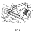
- FIG. 1 partially illustrates an example of manufacture of a thermal protection device intended to protect the internal wall of a conduit intended to channel an ablative flow.
- the method given by way of example consists in winding around a suitable mandrel 1, a fringed mesh or textile 2 of a type easily supplied by a weaving workshop.
- Said fringed textile such as braid, braid or fringed ribbon has a non-deformable mesh part 2A comprising meshes of small dimensions, and fringes or fibers 2B.
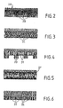
- fringed stripes of profiles similar to those represented in FIGS. 2, 3, 4, 5 or 6 such as the Manufactures Réunies de Saint-Chamond can provide, were wound on a cylindrical chuck with a diameter of 214 mm, length of 200 mm.
- the impregnation was carried out by passing through a silicone bath loaded with silica and silicon carbide (for example of the RTV 630 GE type or equivalent, with 18% silicon carbide). After soaking, the binder rate was regulated by forced passage of the impregnated braid in a calibrated 4 mm slot.
- silica and silicon carbide for example of the RTV 630 GE type or equivalent, with 18% silicon carbide.
- the angle of inclination of the fibers of said braid on the generatrix of the mandrel was given by the chamfer of the winding starting flange 5 and in the present case was chosen to be 45 °.
- the winding pitch was 2 mm, with a speed of rotation of the mandrel of 2 revolutions / minute.
- the ablation layer was formed by pressing with a punch whose pressing surface was parallel to the surface of the chamfer of the starting flange. The pressure applied was 50 bars.
- the layer was then polymerized by heating at 60 ° for at least 4 hours.
- the composition of the protective layer was such that the fringed reinforcement constituted 15 to 18% by weight of the material.
- the samples were subjected to tests in a ramjet combustion chamber, at a temperature above 2000 ° C and the high frequency vibrations (1300 Hz) which accompany combustion.
- the duration of a test was several tens of seconds.
- the temperature on the external wall of the test chamber barely reached 90 ° C, 25 seconds after stopping the combustion.
- a fringed reinforcement with a reduced carbon content was produced according to a variant of the process, explained below.
- the fringed braid was chosen depleted in elementary fibers (1000 to 3000 filaments per strand).
- a silicone composition loaded with zirconia or silicon carbide and short fibers (5 mm) of carbon or silica or silicon carbide was introduced.
- the composition of the addition was: RTV 630 76%; carbon fiber 5 mm 6%; SiC 18%.
- the oriented reinforcement ratio of the thermal protection obtained has been lowered to 8 to 11% by weight.
- the cold wall temperature measured after testing, was found to be less than 65 ° C.
- the adoption of an ablation layer armed with fringed braids obtained from silicon carbide and produced from wicks containing 500 filaments has enabled a significant reduction in the thermal conductivity of the protection during duration of use.
- the use of silica fibers has likewise made it possible to reduce the conductivity of the protective device.
- the protective device was made of a rigid material with very high thermal characteristics obtained by the adoption for the impregnation of the fringed braid of a thermosetting and thermosetting resin, such as a phenolic resin.
- FIG. 5 Another definition of the protective device called for the use of a fringed braid comprising in its binding a wick of carbon as represented by FIG. 5, associated with the adoption a procedure comprising, on the one hand, a non-contiguous helical winding with, on the other hand, after removal of the solvents, a molding under a pressure of 20 to 40 MPa.
- the protective device thus produced was in the form of a rigid tube with reinforced mechanical strength.
- FIG. 2 represents free strands 2B secured by ligatures or bindings forming the mesh part 2A.
- the fringes are constituted by curly strands 2C.
- the fringes of FIG. 4 alternately comprise 2D free strands and 2E curly strands which jointly form slots.
- the fringed mesh of FIG. 5 comprises free strands 2B similar to those of FIG. 2, and a transverse wick 2F taken in the binding 2A.
- FIG. 6 represents free 2D and looped strands 2E superimposed.
- the fringed mesh instead of being a ribbon wound in a helix, in the case of the internal protection of a conduit can be a flexible fringed woven panel, curved so as to envelop the mandrel 1.
- the percentage by weight of the reinforcement relative to the thermal protection device can be, for each determined type of fringed mesh, at a value chosen between 5 and 80%; the proportion of the mesh relative to said device is in practice defined to within 2%.
- the invention applies to the protection of hollow structures in monotonous progressive section by means of a binder (generally a polymerized insulating resin containing a reinforcement).
- a binder generally a polymerized insulating resin containing a reinforcement.
Landscapes
- Engineering & Computer Science (AREA)
- Mechanical Engineering (AREA)
- Chemical & Material Sciences (AREA)
- Combustion & Propulsion (AREA)
- General Engineering & Computer Science (AREA)
- Composite Materials (AREA)
- Textile Engineering (AREA)
- Reinforced Plastic Materials (AREA)
- Moulding By Coating Moulds (AREA)
- Discharge Heating (AREA)
- Professional, Industrial, Or Sporting Protective Garments (AREA)
- Thermal Insulation (AREA)
- Perforating, Stamping-Out Or Severing By Means Other Than Cutting (AREA)
- Vibration Prevention Devices (AREA)
- Lining Or Joining Of Plastics Or The Like (AREA)
Priority Applications (1)
| Application Number | Priority Date | Filing Date | Title |
|---|---|---|---|
| AT85401601T ATE39545T1 (de) | 1984-08-14 | 1985-08-06 | Ablations- und vibrationsfester thermoschutz und herstellungsverfaren. |
Applications Claiming Priority (2)
| Application Number | Priority Date | Filing Date | Title |
|---|---|---|---|
| FR8412782A FR2569237B1 (fr) | 1984-08-14 | 1984-08-14 | Dispositif de protection thermique resistant a l'ablation et aux vibrations, et un procede de fabrication |
| FR8412782 | 1984-08-14 |
Publications (2)
| Publication Number | Publication Date |
|---|---|
| EP0174886A1 EP0174886A1 (fr) | 1986-03-19 |
| EP0174886B1 true EP0174886B1 (fr) | 1988-12-28 |
Family
ID=9307025
Family Applications (1)
| Application Number | Title | Priority Date | Filing Date |
|---|---|---|---|
| EP85401601A Expired EP0174886B1 (fr) | 1984-08-14 | 1985-08-06 | Dispositif de protection thermique résistant à l'ablation et aux vibrations, et un procédé de fabrication |
Country Status (8)
| Country | Link |
|---|---|
| US (1) | US4655866A (cs) |
| EP (1) | EP0174886B1 (cs) |
| JP (1) | JPS61105397A (cs) |
| AT (1) | ATE39545T1 (cs) |
| AU (1) | AU569218B2 (cs) |
| CA (1) | CA1240599A (cs) |
| DE (1) | DE3567061D1 (cs) |
| FR (1) | FR2569237B1 (cs) |
Families Citing this family (33)
| Publication number | Priority date | Publication date | Assignee | Title |
|---|---|---|---|---|
| US5007343A (en) * | 1982-05-17 | 1991-04-16 | Hercules Incorporated | Rocket motor insulation and like made with thin tacky ribbon |
| FR2610044A1 (fr) * | 1986-10-14 | 1988-07-29 | Gen Electric | Systeme de propulsion comportant une garniture perfectionnee de la chambre de combustion et procede de fabrication d'une telle fabrication |
| DE3638658C1 (de) * | 1986-11-12 | 1988-04-21 | Daimler Benz Ag | Waermedaemmende Auskleidung fuer eine Gasturbine |
| US5236529A (en) * | 1989-05-16 | 1993-08-17 | Aerospatiale Societe Nationale Industrielle | Fringed thermal protection device and method of manufacturing it |
| FR2647187B1 (fr) * | 1989-05-16 | 1991-08-30 | Aerospatiale | Dispositif frange de protection thermique de structure, et procede adapte a sa fabrication |
| FR2652036B1 (fr) * | 1989-09-19 | 1991-12-27 | Aerospatiale | Revetement de protection thermique, un procede et une installation pour sa fabrication. |
| US5232534A (en) * | 1989-09-19 | 1993-08-03 | Aerospatiale Soiete Nationale Industrielle | Thermal protection coating, and method and installation for manufacturing it |
| US5048581A (en) * | 1990-05-03 | 1991-09-17 | Weyerhaeuser Company | Veneer tenderizer apparatus and process |
| FR2665860B1 (fr) * | 1990-08-14 | 1994-04-08 | Aerospatiale Ste Nationale Indle | Dispositif de protection thermique de la paroi interne d'une structure creuse soumise a un ecoulement ablatif et son procede de fabrication. |
| GB9108909D0 (en) * | 1991-04-25 | 1991-06-12 | Dow Corning Gmbh | Siloxane ablative compositions |
| US5285592A (en) * | 1991-10-31 | 1994-02-15 | Atlantic Research Corporation | Motor case with composite overwrap and method |
| KR100209304B1 (ko) * | 1995-08-31 | 1999-07-15 | 최동환 | 복합재 압력용기와의 접착력이 증진된 인슈레이션 및 그 제조방법 |
| FR2740068B1 (fr) * | 1995-10-20 | 1998-01-09 | Aerospatiale | Piece en materiau de protection thermique basse densite renforce et son procede d'obtention |
| US5985405A (en) * | 1996-01-30 | 1999-11-16 | Textron Systems Corporation | Three dimensionally reinforced ablative/insulative composite |
| EP0877893B1 (en) * | 1996-01-30 | 2001-09-19 | Textron Systems Corporation | Three-dimensionally reinforced ablative/insulative composite |
| FR2757902B1 (fr) | 1996-12-26 | 1999-03-26 | Aerospatiale | Dispositif et procede pour la protection thermique d'une surface vis-a-vis d'un environnement thermiquement et mecaniquement agressif |
| NL1007281C2 (nl) * | 1997-10-15 | 1999-04-19 | Syncoglas Sa Nv | Driedimensionaal versterkingsmateriaal. |
| US6386110B1 (en) * | 2000-12-11 | 2002-05-14 | The United States Of America As Represented By The Secretary Of The Navy | Deforming charge assembly and method of making same |
| ITTO20011161A1 (it) * | 2001-12-12 | 2003-06-12 | Fiatavio Spa | Metodo per la realizzazione di un involucro coibentato per un propulsore a razzo, ed involucro coibentato per un propulsore a razzo realizza |
| US6889464B2 (en) | 2003-06-04 | 2005-05-10 | Michael K. Degerness | Composite structural member |
| RU2274758C1 (ru) * | 2004-08-12 | 2006-04-20 | Государственное унитарное предприятие "Конструкторское бюро приборостроения" | Способ изготовления ракетного двигателя твердого топлива и ракетный двигатель твердого топлива |
| CN100467348C (zh) * | 2007-01-08 | 2009-03-11 | 新康电脑科技(苏州)有限公司 | 防止航天飞机及其外燃料箱隔热层泡沫块脱落的方法 |
| RU2354842C2 (ru) * | 2007-05-30 | 2009-05-10 | Открытое акционерное общество Научно-производственное объединение "Искра" | Способ формирования теплозащитного покрытия днища корпуса ракетного двигателя на твердом топливе из композиционного материала |
| RU2453720C1 (ru) * | 2010-12-30 | 2012-06-20 | Открытое акционерное общество Научно-производственное объединение "Искра" | Способ изготовления теплозащитного покрытия |
| FR2974751B1 (fr) * | 2011-05-06 | 2013-06-14 | Roxel France | Nouvelles protections thermiques obtenues par procede d'enroulement filamentaire et leur utilisation |
| FR2974806B1 (fr) * | 2011-05-06 | 2014-08-08 | Roxel France | Nouvelles protections thermiques elastomeriques obtenues par procede d'injection et leur utilisation |
| DE102011113539B4 (de) * | 2011-09-15 | 2015-10-01 | Bayern-Chemie Gesellschaft Für Flugchemische Antriebe Mbh | Thermalisolation für Raketentriebwerke |
| US9976687B2 (en) | 2012-05-18 | 2018-05-22 | Saprex, Llc | Breathable multi-component exhaust insulation system |
| US9388515B2 (en) | 2012-09-28 | 2016-07-12 | Saprex, Llc | Heat curable composite textile |
| WO2016039716A1 (en) * | 2014-09-08 | 2016-03-17 | Siemens Aktiengesellschaft | Insulating system for surface of gas turbine engine component |
| JP6802901B2 (ja) | 2016-04-15 | 2020-12-23 | サプレックス,リミテッド・ライアビリティ・カンパニー | 複合材料絶縁システム |
| MX2019005812A (es) | 2016-11-18 | 2019-10-07 | Saprex Llc | Sistema de aislamiento compuesto. |
| CN109796872A (zh) * | 2019-01-09 | 2019-05-24 | 上海交通大学 | 有机硅树脂和钡酚醛树脂复合耐烧蚀隔热涂料及其应用 |
Family Cites Families (17)
| Publication number | Priority date | Publication date | Assignee | Title |
|---|---|---|---|---|
| US3207640A (en) * | 1958-02-18 | 1965-09-21 | Avco Corp | Method of making reinforced material |
| US3140968A (en) * | 1960-01-11 | 1964-07-14 | H I Thompson Fibert Glass Comp | Method and apparatus for helically winding strips on edge under pressure |
| US3200750A (en) * | 1962-03-15 | 1965-08-17 | Dale L Burrows | Insulating device |
| US3187503A (en) * | 1962-05-01 | 1965-06-08 | Bell Aerospace Corp | Rocket engine construction |
| CH429466A (fr) * | 1962-12-21 | 1967-01-31 | Studebaker Corp | Paroi de section annulaire résistant aux hautes températures et dont une face est destinée à venir en contact avec un écoulement de fluide à grande vitesse |
| US3311013A (en) * | 1963-01-09 | 1967-03-28 | Aerojet General Co | Propellant liner |
| FR1359967A (fr) * | 1963-04-08 | 1964-04-30 | Haveg Industries Inc | Nouvel isolateur thermique |
| FR1360411A (fr) * | 1963-04-10 | 1964-05-08 | Haveg Industries Inc | Nouveau produit d'isolation thermique |
| US3573123A (en) * | 1966-05-11 | 1971-03-30 | United Aircraft Corp | Composite high temperature resistant material and method of fabrication |
| FR1518681A (fr) * | 1966-11-08 | 1968-03-29 | Tech Du Verre Tisse | Matériau pour la constitution de structures dites ablatives protégeant des organessoumis à des températures élevées |
| US3577294A (en) * | 1969-03-17 | 1971-05-04 | Constant David | Method for making 3-d filament reinforced articles |
| US3641870A (en) * | 1970-06-04 | 1972-02-15 | Us Army | Shingle-wrap liner for a gun barrel |
| US3960626A (en) * | 1971-01-08 | 1976-06-01 | Martin Marietta Corporation | Method of making high performance ablative tape |
| US3933310A (en) * | 1974-07-11 | 1976-01-20 | Thiokol Corporation | Rocket nozzle construction and surfaces impervious to hot, high velocity gases |
| CA1060330A (en) * | 1975-11-06 | 1979-08-14 | Jacques Ratte | Insulation system for rocket motors |
| US4426038A (en) * | 1982-01-11 | 1984-01-17 | Thiokol Corporation | Non-radiating extendible cloth exit cone for rocket nozzles |
| DE3247414C2 (de) * | 1982-12-22 | 1986-10-23 | Messerschmitt-Bölkow-Blohm GmbH, 8000 München | Verfahren zur Herstellung einer von einer Matte durchsetzten Ablationsschicht |
-
1984
- 1984-08-14 FR FR8412782A patent/FR2569237B1/fr not_active Expired
-
1985
- 1985-08-05 AU AU45773/85A patent/AU569218B2/en not_active Ceased
- 1985-08-06 DE DE8585401601T patent/DE3567061D1/de not_active Expired
- 1985-08-06 AT AT85401601T patent/ATE39545T1/de not_active IP Right Cessation
- 1985-08-06 EP EP85401601A patent/EP0174886B1/fr not_active Expired
- 1985-08-09 CA CA000488390A patent/CA1240599A/en not_active Expired
- 1985-08-09 US US06/764,068 patent/US4655866A/en not_active Expired - Lifetime
- 1985-08-12 JP JP60177458A patent/JPS61105397A/ja active Granted
Also Published As
| Publication number | Publication date |
|---|---|
| JPS61105397A (ja) | 1986-05-23 |
| EP0174886A1 (fr) | 1986-03-19 |
| AU569218B2 (en) | 1988-01-21 |
| ATE39545T1 (de) | 1989-01-15 |
| CA1240599A (en) | 1988-08-16 |
| US4655866A (en) | 1987-04-07 |
| FR2569237B1 (fr) | 1987-01-09 |
| FR2569237A1 (fr) | 1986-02-21 |
| AU4577385A (en) | 1986-02-20 |
| JPH0369040B2 (cs) | 1991-10-30 |
| DE3567061D1 (en) | 1989-02-02 |
Similar Documents
| Publication | Publication Date | Title |
|---|---|---|
| EP0174886B1 (fr) | Dispositif de protection thermique résistant à l'ablation et aux vibrations, et un procédé de fabrication | |
| CA2820415C (fr) | Structure fibreuse pour piece en materiau composite ayant une ou plusieurs parties en forme d'arche | |
| EP0398787B1 (fr) | Dispositif frangé de protection thermique de structure et procédé adapté à sa fabrication | |
| FR2635773A1 (fr) | Materiau composite a fibres de renforcement en carbone et son procede de fabrication | |
| FR2611198A1 (fr) | Materiau composite a matrice et fibres de renforcement carbonees et son procede de fabrication | |
| EP2681036B1 (fr) | Piece en materiau composite comportant des elements de fixation | |
| EP3393764A1 (fr) | Carter allégé en matériau composite et son procédé de fabrication | |
| WO1996030317A1 (fr) | Materiau composite protege contre l'oxydation par matrice autocicatrisante et son procede de fabrication | |
| WO2016132042A1 (fr) | Procédé de fabrication d'une aube de turbomachine en matériau composite | |
| EP0517593B1 (fr) | Chemise de tube de canon en matériau composite, et son procédé de fabrication | |
| FR2695121A1 (fr) | Procédé de fabrication un élément de matrice creux, élément de graphite pour la mise en Óoeuvre du procédé et élément de matrice obtenu. | |
| WO2018234687A1 (fr) | Outillage et procédé d'imprégnation d'une préforme fibreuse de révolution | |
| FR3084088A1 (fr) | Texture fibreuse pour carter en materiau composite a resistance a l'impact amelioree | |
| FR3045448A1 (fr) | Carter allege en materiau composite et son procede de fabrication | |
| WO2022219263A1 (fr) | Procede de fabrication d'une aube creuse de turbomachine | |
| CA2225794C (fr) | Dispositif et procede pour la protection thermique d'une surface vis-a-vis d'un environnement thermiquement et mecaniquement agressif | |
| FR3045456A1 (fr) | Carter allege en materiau composite et son procede de fabrication | |
| EP0471605B1 (fr) | Dispositif de protection thermique de la paroi interne d'une structure creuse soumise à un écoulement ablatif et son procédé de fabrication | |
| WO2023194692A1 (fr) | Pièce de révolution en matériau composite a capacité de rétention améliorée | |
| FR3141164A1 (fr) | Preforme fibreuse et son procede de fabrication pour realiser une piece en materiau composite a matrice ceramique | |
| WO2025238317A1 (fr) | Procede de fabrication d'une piece de revolution en materiau composite avec l'insertion d'un antiadhesif inter-plis | |
| EP0230161B1 (fr) | Procédé de fabrication par retrait thermique de pièces tubulaires tissées, Formées au moins en partie de fibres de carbone | |
| FR3162017A1 (fr) | Procédé de fabrication d’une pièce de révolution en matériau composite avec portion à ténacité réduite inter-plis | |
| FR2468135A1 (fr) | Procede de fabrication de cables optiques et cables ainsi obtenus |
Legal Events
| Date | Code | Title | Description |
|---|---|---|---|
| PUAI | Public reference made under article 153(3) epc to a published international application that has entered the european phase |
Free format text: ORIGINAL CODE: 0009012 |
|
| AK | Designated contracting states |
Kind code of ref document: A1 Designated state(s): AT BE CH DE GB IT LI NL SE |
|
| 17P | Request for examination filed |
Effective date: 19860418 |
|
| 17Q | First examination report despatched |
Effective date: 19870114 |
|
| ITF | It: translation for a ep patent filed | ||
| GRAA | (expected) grant |
Free format text: ORIGINAL CODE: 0009210 |
|
| AK | Designated contracting states |
Kind code of ref document: B1 Designated state(s): AT BE CH DE GB IT LI NL SE |
|
| REF | Corresponds to: |
Ref document number: 39545 Country of ref document: AT Date of ref document: 19890115 Kind code of ref document: T |
|
| REF | Corresponds to: |
Ref document number: 3567061 Country of ref document: DE Date of ref document: 19890202 |
|
| GBT | Gb: translation of ep patent filed (gb section 77(6)(a)/1977) | ||
| PLBE | No opposition filed within time limit |
Free format text: ORIGINAL CODE: 0009261 |
|
| STAA | Information on the status of an ep patent application or granted ep patent |
Free format text: STATUS: NO OPPOSITION FILED WITHIN TIME LIMIT |
|
| 26N | No opposition filed | ||
| ITTA | It: last paid annual fee | ||
| EAL | Se: european patent in force in sweden |
Ref document number: 85401601.1 |
|
| PGFP | Annual fee paid to national office [announced via postgrant information from national office to epo] |
Ref country code: CH Payment date: 20010814 Year of fee payment: 17 |
|
| PGFP | Annual fee paid to national office [announced via postgrant information from national office to epo] |
Ref country code: AT Payment date: 20010821 Year of fee payment: 17 |
|
| PGFP | Annual fee paid to national office [announced via postgrant information from national office to epo] |
Ref country code: SE Payment date: 20010822 Year of fee payment: 17 |
|
| PGFP | Annual fee paid to national office [announced via postgrant information from national office to epo] |
Ref country code: NL Payment date: 20010827 Year of fee payment: 17 |
|
| PGFP | Annual fee paid to national office [announced via postgrant information from national office to epo] |
Ref country code: BE Payment date: 20010907 Year of fee payment: 17 |
|
| REG | Reference to a national code |
Ref country code: GB Ref legal event code: IF02 |
|
| PG25 | Lapsed in a contracting state [announced via postgrant information from national office to epo] |
Ref country code: AT Free format text: LAPSE BECAUSE OF NON-PAYMENT OF DUE FEES Effective date: 20020806 |
|
| PG25 | Lapsed in a contracting state [announced via postgrant information from national office to epo] |
Ref country code: SE Free format text: LAPSE BECAUSE OF NON-PAYMENT OF DUE FEES Effective date: 20020807 |
|
| PG25 | Lapsed in a contracting state [announced via postgrant information from national office to epo] |
Ref country code: LI Free format text: LAPSE BECAUSE OF NON-PAYMENT OF DUE FEES Effective date: 20020831 Ref country code: CH Free format text: LAPSE BECAUSE OF NON-PAYMENT OF DUE FEES Effective date: 20020831 Ref country code: BE Free format text: LAPSE BECAUSE OF NON-PAYMENT OF DUE FEES Effective date: 20020831 |
|
| BERE | Be: lapsed |
Owner name: *AEROSPATIALE SOC. NATIONALE INDUSTRIELLE Effective date: 20020831 |
|
| PG25 | Lapsed in a contracting state [announced via postgrant information from national office to epo] |
Ref country code: NL Free format text: LAPSE BECAUSE OF NON-PAYMENT OF DUE FEES Effective date: 20030301 |
|
| EUG | Se: european patent has lapsed | ||
| REG | Reference to a national code |
Ref country code: CH Ref legal event code: PL |
|
| NLV4 | Nl: lapsed or anulled due to non-payment of the annual fee |
Effective date: 20030301 |
|
| PGFP | Annual fee paid to national office [announced via postgrant information from national office to epo] |
Ref country code: GB Payment date: 20030804 Year of fee payment: 19 |
|
| PGFP | Annual fee paid to national office [announced via postgrant information from national office to epo] |
Ref country code: DE Payment date: 20030807 Year of fee payment: 19 |
|
| PG25 | Lapsed in a contracting state [announced via postgrant information from national office to epo] |
Ref country code: GB Free format text: LAPSE BECAUSE OF NON-PAYMENT OF DUE FEES Effective date: 20040806 |
|
| PG25 | Lapsed in a contracting state [announced via postgrant information from national office to epo] |
Ref country code: DE Free format text: LAPSE BECAUSE OF NON-PAYMENT OF DUE FEES Effective date: 20050301 |
|
| GBPC | Gb: european patent ceased through non-payment of renewal fee |
Effective date: 20040806 |