EP0174763B1 - Etikettiervorrichtung - Google Patents
Etikettiervorrichtung Download PDFInfo
- Publication number
- EP0174763B1 EP0174763B1 EP19850306043 EP85306043A EP0174763B1 EP 0174763 B1 EP0174763 B1 EP 0174763B1 EP 19850306043 EP19850306043 EP 19850306043 EP 85306043 A EP85306043 A EP 85306043A EP 0174763 B1 EP0174763 B1 EP 0174763B1
- Authority
- EP
- European Patent Office
- Prior art keywords
- label
- assembly
- cam
- labeling
- gripper
- Prior art date
- Legal status (The legal status is an assumption and is not a legal conclusion. Google has not performed a legal analysis and makes no representation as to the accuracy of the status listed.)
- Expired
Links
- 238000002372 labelling Methods 0.000 title claims description 141
- 230000000712 assembly Effects 0.000 claims description 26
- 238000000429 assembly Methods 0.000 claims description 26
- 238000000034 method Methods 0.000 claims description 24
- NJPPVKZQTLUDBO-UHFFFAOYSA-N novaluron Chemical compound C1=C(Cl)C(OC(F)(F)C(OC(F)(F)F)F)=CC=C1NC(=O)NC(=O)C1=C(F)C=CC=C1F NJPPVKZQTLUDBO-UHFFFAOYSA-N 0.000 claims description 12
- 230000007246 mechanism Effects 0.000 claims description 11
- 230000008569 process Effects 0.000 claims description 11
- 239000012530 fluid Substances 0.000 claims description 6
- 230000000087 stabilizing effect Effects 0.000 claims description 6
- 238000000926 separation method Methods 0.000 claims description 5
- 238000004891 communication Methods 0.000 claims description 4
- 230000000694 effects Effects 0.000 claims description 4
- 230000008878 coupling Effects 0.000 claims description 3
- 238000010168 coupling process Methods 0.000 claims description 3
- 238000005859 coupling reaction Methods 0.000 claims description 3
- 230000006641 stabilisation Effects 0.000 claims description 2
- 238000011105 stabilization Methods 0.000 claims description 2
- 230000002093 peripheral effect Effects 0.000 claims 2
- 230000007257 malfunction Effects 0.000 description 12
- 238000010276 construction Methods 0.000 description 7
- 239000000463 material Substances 0.000 description 7
- 238000004519 manufacturing process Methods 0.000 description 6
- 235000014214 soft drink Nutrition 0.000 description 6
- 230000009471 action Effects 0.000 description 3
- 230000001133 acceleration Effects 0.000 description 2
- 230000003247 decreasing effect Effects 0.000 description 2
- 239000004519 grease Substances 0.000 description 2
- 238000005461 lubrication Methods 0.000 description 2
- 239000002184 metal Substances 0.000 description 2
- 238000007639 printing Methods 0.000 description 2
- KHOITXIGCFIULA-UHFFFAOYSA-N Alophen Chemical compound C1=CC(OC(=O)C)=CC=C1C(C=1N=CC=CC=1)C1=CC=C(OC(C)=O)C=C1 KHOITXIGCFIULA-UHFFFAOYSA-N 0.000 description 1
- 230000002411 adverse Effects 0.000 description 1
- 230000008901 benefit Effects 0.000 description 1
- 230000008859 change Effects 0.000 description 1
- 230000006835 compression Effects 0.000 description 1
- 238000007906 compression Methods 0.000 description 1
- 239000000356 contaminant Substances 0.000 description 1
- 239000002537 cosmetic Substances 0.000 description 1
- 230000000593 degrading effect Effects 0.000 description 1
- 230000023077 detection of light stimulus Effects 0.000 description 1
- 239000013536 elastomeric material Substances 0.000 description 1
- 239000011521 glass Substances 0.000 description 1
- 238000009434 installation Methods 0.000 description 1
- 210000002445 nipple Anatomy 0.000 description 1
- 230000004044 response Effects 0.000 description 1
- 230000001360 synchronised effect Effects 0.000 description 1
Images


Classifications
-
- B—PERFORMING OPERATIONS; TRANSPORTING
- B65—CONVEYING; PACKING; STORING; HANDLING THIN OR FILAMENTARY MATERIAL
- B65C—LABELLING OR TAGGING MACHINES, APPARATUS, OR PROCESSES
- B65C3/00—Labelling other than flat surfaces
- B65C3/06—Affixing labels to short rigid containers
- B65C3/065—Affixing labels to short rigid containers by placing tubular labels around the container
-
- B—PERFORMING OPERATIONS; TRANSPORTING
- B29—WORKING OF PLASTICS; WORKING OF SUBSTANCES IN A PLASTIC STATE IN GENERAL
- B29C—SHAPING OR JOINING OF PLASTICS; SHAPING OF MATERIAL IN A PLASTIC STATE, NOT OTHERWISE PROVIDED FOR; AFTER-TREATMENT OF THE SHAPED PRODUCTS, e.g. REPAIRING
- B29C63/00—Lining or sheathing, i.e. applying preformed layers or sheathings of plastics; Apparatus therefor
- B29C63/18—Lining or sheathing, i.e. applying preformed layers or sheathings of plastics; Apparatus therefor using tubular layers or sheathings
-
- B—PERFORMING OPERATIONS; TRANSPORTING
- B29—WORKING OF PLASTICS; WORKING OF SUBSTANCES IN A PLASTIC STATE IN GENERAL
- B29L—INDEXING SCHEME ASSOCIATED WITH SUBCLASS B29C, RELATING TO PARTICULAR ARTICLES
- B29L2031/00—Other particular articles
- B29L2031/712—Containers; Packaging elements or accessories, Packages
- B29L2031/7158—Bottles
Definitions
- the present invention relates generally to apparatus and methods for labeling products and in particular to an apparatus and method for applying flexible, tubular labels to product containers.
- the labeling of product containers can be done by various methods. Early methods involved either printing information directly onto the container or alternately printing the information on a label which was then adhesively bonded to the container.
- a more recent labeling method involves the application of a tubular, flexible label to the bottle.
- the label is preprinted with the product's name and product information and the label is then pulled over the container either manually or by machine.
- tubular, flexible labels have become a common way of labeling plastic, "2 liter" bottles which are popular containers for soft drinks.
- these plastic containers are replacing glass bottles and metal cans more and more each year.
- the labeling of these types of containers can be time consuming and add significant cost to the product package.
- Bottlers however, continuously strive to reduce operating costs.
- the labor costs are reduced by increasing the production speeds of the bottling and the label applying machinery.
- the material cost is reduced by reducing material thickness of the label itself.
- the labels are usually supplied in the form of a continuous web.
- the individual labels are defined by longitudinally spaced, transverse perforations.
- the web is fed over a mandrel positioned above the bottle to be labeled.
- a gripper assembly grips the bottom of the label and pulls it downwardly over the bottle.
- the web is braked to prevent further movement thus causing the label held by the gripper assembly to sever itself from the remainder of the supply.
- U.S. Patent No. 4,412,876 included a labeling assembly that was reciprocally actuated through a labeling cycle by a harmonic crank mechanism rotated by a drive motor.
- the bottles to be labeled were fed into the labeling machine by a separate drive arrangement including a clutch and drive motor that were energized to actuate an L-shaped pusher assembly for advancing the bottles.
- the labeling assembly of the machine disclosed in U.S. Patent No. 4,412,876 included a clamping arrangement by which a label to be applied was gripped. At the commencement of the labeling cycle, the region clamped by the labeling assembly was stretched in order to clear the periphery of the bottle. It has been found that as the thickness of the label material is reduced, the stretching of the lower region of the label after engagement by the clamp, can cause permanent distortion in the label. This distortion compromises the appearance of the label. Since the cosmetic appearance of the label after installation is important to the packager, it is believed that the bottling industry would find the distortion unacceptable.
- the present invention provides a new and improved apparatus and method for applying tubular, flexible labels to product containers such as plastic soft drink bottles.
- the disclosed apparatus is capable of extremely high speed operation without damage to bottles or labels and can install labels having reduced material thickness with minimal distortion to the label.
- a labeling apparatus comprising:
- the invention also provides a drive system for actuating a labeling assembly forming a part of a labeling machine for applying tubular, flexible labels to product containers, comprising:
- the invention also provides a process for applying tubular, flexible labels to product containers, as specified in Claim 24.
- the labeling assembly is driven through a label applying stroke and a return stroke.
- a label is pulled onto the product container and severed from the supply.
- the label assembly releases the label and then is retracted to allow the labeled bottle to exit the work station and to allow an unlabeled bottle to advance into the work station.
- the next label to be applied is engaged just prior to beginning the label applying stroke.
- the drive system actuates the labeling assembly at different rates and/or accelerations during the label applying and return strokes.
- the average speed of the label applying stroke is slower than the return stroke. This permits an optimized rate of label application without risk of damage to the label as it is being applied to the container.
- throughput is increased, as contrasted with the described prior machine, by substantially increasing the rate at which the labeling assembly returns after applying a label.
- the rate of the label applying stroke is slower than the return stroke, thus reducing the risk of a misfeed or damage to the label.
- the drive system includes a cam rotatably driven by a suitable drive motor.
- the cam defines a profile having a rather steep rise for actuating the labeling assembly through the return stroke and a gradual drop for driving the assembly through the label applying stroke at lower average speed as compared to the return stroke.
- a label assembly actuating arm is pivotally connected to the frame.
- the arm carries a cam follower which rides against the actuating cam.
- the arm is also connected to the labeling assembly so that motion transmitted to the cam follower by the cam produces a reciprocating motion in the labeling assembly.
- the cam follower is biased into abutting contact with the cam.
- the biasing is achieved by a pneumatic cylinder which is pressurized with a predetermined air pressure.
- the air is captured in the air cylinder and acts as a pneumatic spring.
- the contact between the cam follower and cam is monitored by a sensor. Should the cam follower separate from the cam as would occur in the case of a malfunction in the labeling assembly, movement in the drive system is immediately arrested.
- rotation in the cam is terminated virtually instantly by a brake system which is actuated in response to the sensed malfunction.
- a malfunction or jam in the label applying apparatus requires that the apparatus be raised in order to clear the malfunction.
- a counterweight was used to balance the weight of the labeling assembly so that an operator could manually raise the assembly when necessary.
- the pneumatic cylinder although normally acting as a biasing device, is also used as a lifting device for the labeling assembly.
- a control is provided for pressurizing and extending the pneumatic cylinder. The extension of the cylinder raises the labeling assembly.
- the operator merely actuates the control to depressurize the cylinder thus lowering the labeling assembly and associated actuating lever into contact with the drive cam.
- a pusher assembly for indexing or advancing product containers into the labeling station is actuated by the same drive system that actuates the labeling assembly. This feature eliminates the need for a separate clutch and drive motor for operating the advancing mechanism.
- the drive system includes an indexing cam, co-driven with the main drive cam.
- the second cam actuates linkage connected to the pusher assembly.
- the linkage for actuating the pusher assembly also includes a pressurized pneumatic cylinder for exerting a biasing force on the associated cam follower to maintain contact between it and the indexing cam.
- an improved container stabilizing device is employed to maintain the position of a container at the labeling station.
- a vacuum port was located at the labeling station which during operation was connected to a continuous source of vacuum.
- a perforate plate covered the vacuum port and formed a support for the bottle being labeled.
- the label container was pushed off the vacuum port by next adjacent container.
- the container to be labeled is supported by a vacuum pedestal, including a vacuum port, located in alignment with the labeling apparatus, that includes a valve for controlling the communication of a vacuum source with the vacuum port.
- a vacuum pedestal including a vacuum port, located in alignment with the labeling apparatus, that includes a valve for controlling the communication of a vacuum source with the vacuum port.
- the vacuum generated gripping force is terminated at the conclusion of the labeling process to facilitate sliding movement of the bottle off the vacuum pedestal.
- the valve is reopened to communicate vacuum to the port as the next bottle to be labeled advances onto the pedestal.
- a filter compartment is located intermediate the vacuum pedestal and the vacuum source to prevent the entry of contaminants into the vacuum system.
- the conduit and filter compartment act as an accumulator when the communication of vacuum to the port is terminated by the valve.
- the valve when the valve initially opens, a large inrush of air occurs and enhances the gripping force on the advancing bottle.
- the sudden surge of air occurs at a rate that is greater than the steady state flow of air into the port and produces an increased temporary gripping force. Since the valve opens as the product to be labeled is advancing onto the perforate port, this initial inrush serves to grip and quickly stabilize the product on the port.
- the disclosed apparatus and method applies tubular labels to product containers such as soft drink bottles at high speeds without degrading the appearance of the label or the reliability of the machine.
- This is achieved by a drive arrangement that applies the label to the product at an average speed that is lower than the average speed at which the labeling assembly is retracted.
- a drive system embodying the present invention can actuate the label applying apparatus at a rate equivalent to 120 operations per minute during the return stroke.
- the label assembly is driven at a rate corresponding to 60 label applications per minute.
- the label applying portion of the operating cycle moves at a rate comparable to that of a prior machine, the increased speed at which the label assembly is returned results in an effective production rate for the improved machine of 90 label applications per minute. This production rate is substantially greater than the production rate of prior machines.
- the labeling apparatus also includes a pair of gripper assemblies which operate together to apply a tubular, flexible label or sleeve to a product container positioned at a labeling station.
- the gripper assemblies are adjustably mounted to a pair of reciprocally movable slide rods such as those shown in Patent No. 4,412,876 which is hereby incorporated by reference.
- Each gripper assembly includes a reciprocally movable cuff for engaging the inside of the label to be applied and a clamping member for clamping the label to the cuff.
- the cuff and clamping member each form part of separate subassemblies, both subassemblies being slidably mounted to a gripper assembly frame.
- the gripper assemblies are raised to a point where the cuffs of each gripper assembly enter the inside of the label to be applied.
- the cuff subassemblies of each assembly are then moved outwardly, i.e., away from the axis of the bottle, so as to expand the lower region of the label in order to clear the periphery of the bottle.
- the cuffs are driven outwardly, the lower region of the label engaged by the gripper assemblies is allowed to expand uniformly around its entire circumference.
- the gripper assemblies do not clamp the label until the label has been stretched by the cuff subassemblies.
- the disclosed apparatus and method eliminates the localized stretching that could occur in prior label installing arrangements.
- clamping surfaces on the cuffs contact gripper pads forming part of the clamping subassemblies.
- the label to be applied is thus clamped between a gripper pad and the cuff clamping surface of each gripper assembly.
- each cuff is moved outwardly, slightly, to further expand the lower region of the label to provide added clearance.
- the clamping subassemblies When the label is pulled into position on the bottle, the clamping subassemblies are retracted in order to release the clamping force on the lower region of the label.
- the friction exerted by the container inhibits further movement of the label.
- the gripper assemblies continue their travel enabling the cuff subassemblies to completely release the lower region of the applied label. After release, the gripper assemblies are retracted to the initial position in order to grip and apply the next label.
- each cuff subassembly is moved outwardly at the commencement of the labeling cycle by a fluid pressure operated actuator.
- the clamping surface of each cuff contacts the gripper pad of its associated clamping subassembly.
- the clamping subassemblies are biased toward the clamping surface of the associated cuff subassembly by a biasing element such as a spring. The clamping force exerted on the cuff is determined by the gripper biasing element.
- each gripper assembly is achieved by a cuff drive cam and cam roller arrangement associated with each gripper assembly.
- the cuff subassembly mounts the cam roller.
- An associated cam including a cam ramp is mounted vertically at the labeling station in alignment with the cam roller.
- cam roller and cam mechanism not only provides additional expansion of the label but more importantly insures that the cuffs are driven to, and remain, outside the periphery of the bottle asthe labeling apparatus is driven through its label applying strobe. The outward position of the cuffs is maintained even if a failure in the cuff actuator should occur.
- Each gripper assembly also includes a lever arrangement including a roller engageable with another cam including a cam ramp mounted atthe labeling station for releasing the clamping force on the label when the label reaches a predetermined position on the container being labeled.
- the lever arrangement is used to drive the clamping subassemblies away from the cuffs near the bottom of the label applying stroke. When the lever engage the cam ramp, the clamping subassemblies are moved outwardly so that the label clamped between the gripper pads and the cuffs is released.
- a stabilizing cam roller is also mounted to each gripper assembly.
- the stabilizing cam roller is oriented with its axis of rotation rotated 90° from the cam roller used to move the cuff subassemblies outwardly.
- the stabilizing cam roller of each gripper assembly is engageable with another surface of the associated cuff drive cam. The engagement between the roller and the cam prevents the gripper assemblies from twisting about their associated slide rods when the gripper release cam is engaged by the associated release lever.
- the present invention thus provides an improved labeling assembly in which localized stretching of a label being applied is minimized. Unlike the prior art, the entire circumference of the lower region of the label is expanded prior to clamping the label.
- the disclosed gripper assemblies are capable of applying labels, constructed from relatively thin materials.
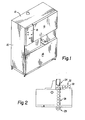
- Figure 1 illustrates the external appearance of a labeling apparatus constructed in accordance with the preferred embodiment of the invention.
- the labeling apparatus includes a sheet metal cabinet formed by a plurality of removable covers 10, 12, 14, 16.
- a control panel 18 contains a plurality of operator controls for controlling the operation of the apparatus.
- the disclosed labeling apparatus is adapted to apply tubular, flexible labels to containers such as "2 liter" soft drink bottles.
- the bottles 20 are brought to the machine on a conveyor, indicated by the reference character 22.
- An L-shaped pusher assembly, indicated generally by the character 24 advances bottles towards a labeling station indicated generally by the reference character 26. After it is labeled, the bottle is pushed out of the labeling position by the next advancing bottle.
- An exit conveyor (not shown) carries the labeled bottles from the exit of the labeling apparatus, indicated generally by the reference character 28.
- a base or lower portion 30 of the apparatus supports and mounts a drive system constructed in accordance with the preferred embodiment of the invention.
- An upper portion 32 defines the labeling station indicated generally by the reference character 26.
- the upper portion 32 includes a supply of labels (not shown) preferably comprising a continuous tubular web 34 (shown only in Figure 8) wound on a supply spindle (not shown), each individual label being defined by a pair of longitudinally spaced, transverse perforations 34a.
- the web of labels is fed over a mandrel 40 (shown in Figure 8 only) and then pulled over a product container 41 positioned below the mandrel. During the application process the label being applied is severed from the web 34.
- the apparatus for applying the label to a container positioned at the labeling station includes a label position detector 42 and a web braking device 44.
- the detector 42 and other parts are omitted from Figure 8 in order to illustrate the details of the mandrel 40 and other related components.
- the web braking device 44 comprises a solenoid operated plunger 44a (shown in Figure 4) which when actuated, clamps the web against the stationary mandrel so that as the leading label is pulled downwardly by a label applying assembly 46, the leading label is severed from the remainder of the web along the label defining perforations 34a (shown in Figure 8).
- the web position detector 42 senses indicia on each successive label when such labels are properly positioned with respect to the mandrel 40 and produces a web braking signal.
- the web position indicia are accurately located on each label and the detector 42 and mandrel 40 are positioned so that the lowermost edge of each label is aligned with the detector 42.
- the detector is preferably designed to detect wave shifted light emitted by a normally invisible, or nearly invisible, registration mark printed on each label.
- the preferred detector 42 can be constructed as disclosed by United States application Serial No. 253,193 filed April 27, 1981 and entitled "Control Marking Detector". Because additional details of the construction and operation of the detector 42 can be had by consulting the above referenced application, no further detailed description is necessary here.
- the detector 42 is adjustably supported relative to the labeling station 26 by a support assembly 48.
- the support assembly 48 includes clamps 49 by which the assembly 48 is connected to supporting rods 51 to enable the support assembly 48 to be adjustably positioned vertically as desired and clamped in place.
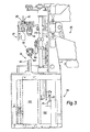
- the label applying assembly 46 is reciprocally movable in a vertical plane by a carriage 50 operatively connected to the drive system located in the base 30 of the apparatus.
- the carriage 50 includes a pair of slide rods 52a, 52b that are slidably supported by upper and lower slide bearings 54, 55.
- left and right hand halves 46a, 46b of the labeling applying apparatus 46 are adjustably clamped to the left and right slide rods 52a, 52b, respectively.
- the reciprocal slide rods 52a, 52b are rigidly interconnected by a cross piece 58. Reciprocal, vertical movement is imparted to the cross piece 58 and hence the slide rods 52a, 52b by a lever arm 60. As viewed in Figure 5, the lever arm 60 is pivotally connected at its leftmost end, to a fixed base plate 62. Preferably, the pivoted end is journaled in a bearing assembly 64. Since the guide rods 52a, 52b are constrained to vertical movement only, a lost motion connection is used between the right end of the lever arm 60 (as viewed in Figure 5) and the cross piece 58.
- a carriage pin 66 attached to the cross piece 58 is received in a slot 68 defined at the right end of the lever arm.
- the pin 66 may include a bearing for reducing the friction between the slot structure 68 and the pin 66. It should be apparent that as the lever arm moves upwardly or downwardly, the change in radial distance between the pivot 64 and the carriage pin 66 is accommodated by transverse movement of the pin within the slot 68.
- the lever arm 60 is raised and lowered about its pivot 64 by a main drive cam 70.
- the cam is rotated about a shaft 72 by a timing belt or chain 74 operatively coupled to a gear box 76.
- the gear box in turn is coupled to a suitable drive motor 77.
- the timing belt 74 is reeved around drive and driven timing sprockets 81, 83 attached to the gearbox 76 and shaft 72, respectively (shown best in Figure 6).
- the lever arm 60 mounts a cam follower 78 intermediate its ends that rides against the cam 70. Rotation of the cam 70 produces angular, reciprocating motion in the lever arm 60 about its pivot 64 which in turn imparts vertical, rectilinear reciprocating movement in the slide rods 52a, 52b and hence the label applying assembly 46.
- the cam follower 78 is biased into continuous contact with the periphery of the cam 70 by a biasing device 80.
- the biasing device comprises a pneumatic cylinder pressurized to a predetermined pressure.
- the cylinder is initially filled with a relatively low pressure, i.e. 0.7 to 1.4kg per sq. cm (10-20 psi). Once pressurized, the discharge of the pressurized air is prevented as by a check valve (not shown) and the cylinder thus acts as a pneumatic spring.
- a sensor monitors the contact between the cam roller 78 and the main drive cam 70 and deactivates the drive system should separation between the follower 78 and cam 70 be detected.
- the sensor is carried by the lever arm 60 and may comprise a light source 84 and a light sensor 86 disposed on opposite sides of the cam follower 78, in alignment with the region of contact between the cam 70 and the cam follower 78 (shown only in Figures 6 and 7). As long as the cam follower remains in contact with the cam, light from the source is blocked. Should the cam follower separate, the light sensor 86 responding to the detection of light would deactivate the drive motor 77 to stop rotation of the cam 70.
- the drive system preferably includes a braking arrangement for arresting motion in the cam virtually instantaneously upon sensing separation of the cam 70 and cam follower 78.
- a brake disc 90 shown in Figure 6 which is also mounted to the shaft 72 and co-driven with the cam 70.
- a pair of disc brake calipers 92 are mounted to a braking plate 96 and overlie portions of the disc 90. Suitable pneumatically operated brake disc calipers are available from Horton Manufacturing Company.
- an operator control located on the operator control panel may be actuated to pressurize the cylinder end 80b of the air cylinder in order to extend the rod 82. It should be apparent that extending the rod 82 causes the lever arm 60 to be driven upwardly and hence raises the slide rods 52a, 52b and label applying assembly 46. When the malfunction has been corrected, the cylinder end 80b is depressurized in order to lower the lever arm 60 until the cam follower 78 contacts the cam 70.
- the shaft 72 also mounts a small timing sprocket 98.
- a timing belt 100 connects the timing sprocket 98 to a digital encoder 102.
- the encoder 102 is connected to an electronic control system (not shown) forming part of the labeling apparatus which effects control of the various labeling functions.
- the digital encoder 102 generates synchronizing signals for the electrical control system so that the various machine functions are coordinated with the position of the main drive cam 70.
- the drive shaft 72 also mounts a second cam 110, smaller than the main drive cam 70.
- the cam 110 reciprocally drives a product indexing lever 112.
- the lever 112 is centrally pivoted at a pivot assembly 114 and mounts a cam follower 116 at its rightmost end (as viewed in Figure 7). The leftmost end is pivotally connected to a drive rod 118.
- a slot 120 formed at the left end of the lever 112 provides for a radial adjustment for modifying the stroke of the rod 118.
- the drive rod 118 is connected to a pusher assembly that is operative to advance containers into the labeling station 26.
- the pusher assembly includes an L-shaped arm 120 that mounts a pusher plate (not shown).
- a linkage (not shown) connected to the actuating rod 118 converts vertical, reciprocating motion in the actuating rod 118 into transverse reciprocating motion in the L-shaped pusher arm towards and away from the labeling station 26.
- an air cylinder (not shown) like the air cylinder 80 is used to bias the lever arm 112 into contact with the product indexing cam 110.
- the drive system of the present invention allows the machine to be operated at a higher production rate without comprising the quality or reliability of the label applying operation.
- This is accomplished by configuring the main drive cam 70 to impart a differential rate of motion to the label applying assembly 46 during the label applying and return strokes.
- the profile of the cam 70 is asymmetrical in shape.
- the fall of the cam occurs much more gradually than the rise of the cam.
- the downward movement of the labeling assembly 46 occurs at a lower average speed than its upward or return movement.
- the fall of the cam occurs over 240° of rotation whereas the rise occurs in 120° of rotation.
- the labeling assembly 46 retracts at twice the rate it applies a label.
- the rate at which containers are labeled by the labeling machine can be increased without adversely affecting the quality and reliability of the label applying procedure.
- the increased speed is achieved by increasing the rate at which the label applying assembly is returned to its starting position.
- the actual label applying motion occurs at an average speed and/or acceleration levels comparable to the speed at which a harmonically driven label assembly would apply the labels.
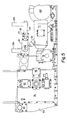
- the container to be labeled is advanced to a position below the mandrel 40.
- Transverse guides 126, 128 center and guide the bottle into the labeling position below the mandrel 40 (shown only in Figure 8).
- a vacuum pedestal 126a is aligned with the mandrel and operates to stabilize or clamp the bottle in proper alignment.
- the pedestal includes a perforate region 130 (a portion of which is shown in Figure 1) which communicates with a source of vacuum.
- the source comprises a vacuum pump 132 (shown in Figures 3 and 5-7). Conduits (not shown) connect the perforate region 130 with the vacuum source.
- the vacuum pedestal is obscured by a cover 126a.
- a filter compartment indicated generally by the reference character 140 is disposed in the flow path intermediate the perforate region 130 and the vacuum pump 132. The filter prevents dirt and other foreign matter, drawn into the vacuum pedestal 126a, from entering the vacuum motor.
- the pedestal includes a butterfly valve assembly 150 rotated between opened and closed position by a rotary solenoid actuator 152.
- the lower end of valve assembly 150 includes a nipple 154 for connection to a vacuum conduit (not shown).
- a shaft 152a of the solenoid actuator 152 is coupled to a valve shaft 156 on which a butterfly plate 158 is mounted, by a coupling 160.
- the actuation of the solenoid valve is controlled by the electrical control system and is synchronized with the bottle advancing mechanism.
- the valve closes to terminate the vacuum force on the labeled container to facilitate its advancement out of the labeling station 26.
- the valve is reopened in order to exert a clamping force on the next container.
- the conduits and filter compartment act as an accumulator so that when the valve is initially opened, a large inrush of air occurs and enhances the initial gripping action and aids in the stabilization and positioning of the bottle to be labeled.
- each assembly includes a cuff 152 and an associated gripper pad assembly 154 which when clamped together are operative to grip a lower portion of a label to be applied.
- the cuff 152 forms part of a laterally movable base plate 156 which is slidably mounted on a pair of guide rods 158, 159.
- a spring 160 biases the base plate towards the center-line of the labeling station.
- the gripper pad assembly is slidably mounted on the base plate by a pair of slide rods 162 (only one slide rod is shown).
- a spring 164 biases the gripper pad assembly 154 towards the cuff 152.
- a lever arrangement 165 cooperates with a cam 166 to produce transverse movement in the gripper assembly 154 at predetermined positions during a labeling cycle.
- a cam roller (not shown) forming part of the base plate structure 156 coacts with a cam 168 defining a ramp 168a.
- the cuff 152 and gripper pad 154 separate when the assembly 46b is at its uppermost position so that a lower region of the next available label can be received.
- an actuator drives the gripper assembly into contact with the cuff 152 so that the label is firmly gripped by the assembly 46b.
- the assembly 46b then moves downwardly along with the gripped label.
- the cam roller forming part of the base plate structure contacts the cam 168a and causes the base plate structure and hence the cuff 152 and gripper pad 154 to move outwardly to clear the periphery of the bottle being labeled.
- the lever 165 contacts the cam and causes the gripper assembly to separate from the cuff thus releasing the label. Further downward movement then allows the cuff to completely release a label allowing the assembly to retract in order to engage another label.
- Figures 8 and 12-14 an improved label applying apparatus is illustrated. Although the label applying mechanism described above and shown in Figure 4 can be used, it is believed that the label applying assembly shown in Figures 8 and 12-14 can install a label on a container with less risk of distortion or damage, especially at the higher speeds achievable by the disclosed labeling machine.
- the improved labeling assembly is adjustably clamped to the actuating rods 52a, 52b in substantially the same way the assembly shown in Figure 4 is clamped.
- the labeling assembly includes left and right gripper assemblies 44a', 44b' connected to the slide rods 52a, 52b respectively.
- Each gripper assembly is effective to grip a lower portion of a label positioned at a labeling station (on the mandrel 40). The label is then pulled downwardly over the container at the labeling station.
- the gripper assemblies 44a', 44b' release the label when properly positioned on the container and then both are driven upwardly again to repeat the label applying cycle.
- the gripper assemblies 44a', 44b' are similarly constructed and in effect are mirror images of each other.
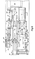
- the detailed construction of the assembly 44a is illustrated in Figures 11-13.
- the gripper assembly 44a includes a rigid support frame 180 which is essentially L-shaped having a vertical wall 180a and a transverse wall 180b.
- a gusset plate 182 extends between the vertical and transverse walls and rigidizes the overall structure.
- the vertical wall 180a of the frame 180 mounts a pair of clamping blocks 184 by which each gripper assembly 44a', 44b' is adjustably clamped to respective slide rods 52a, 52b (shown in Figures 4 and 5).
- the frame 180 slidably mounts a cuff subassembly indicated generally by the reference character 190 and a gripper block subassembly indicated generally by the reference character 192.
- the cuff and gripper block subassemblies 190, 192 cooperate to grip a lead label "L" of the chain or web of labels 34 when the gripper assemblies 44a', 44b' are in their uppermost positions, indicated in phantom by the reference character 196.
- the gripped label "L” is pulled downwardly over a bottle “B” as the gripper assemblies 44a', 44b' are driven downwardly by the drive system.
- the gripper block subassembly 192 includes a pair of slides 200 slidably supported for reciprocating movement by the gusset 182 and a spaced, parallel support wall 202 forming part of the assembly frame 180.
- the slides 200 are preferably supported by linear ball bearings 204 which are available from Thomson Industries, Inc.
- a gripper member 206 is clamped near the ends of the slides 200.
- the gripper member 206 includes a pair of spaced arcuate pads 208, preferably constructed from an elastomeric material which are fixed to a pad support block 210 which in turn is clamped to the slides 200 by a clamping bar 212.
- the cuff subassembly 190 includes a pair of slides 220 which are also slidably supported by bearings 222 mounted in the gusset plate 182 and the support wall 202.
- the bearings 222 are preferably linear ball bearings such as those available from Thomson Industries, Inc.
- a cuff member 224 is mounted near the ends of the slides 220.
- the cuff member 224 defines an arcuate wall 224a which preferably conforms somewhat to the periphery of the bottle "B".
- the cuff member 224 is mounted to the ends of the slides 220 by a clamping arrangement comprising a lower clamp block 226, fastened to the cuff 224 by fasteners 228 and an upper clamp block 230 which is clampingly engaged by fasteners 232 that extend through the lower clamp block 226 and are threadedly received by the upper clamp block 230.
- a pair of spaced, parallel bars 240, 242 are clamped to the slides 220.
- the bars 240, 242 (only the bar 242 is shown), each include a slot 244 and a clamping screw 246 by which the bars are fixed in position to the slides 220.
- a platform 250 is rigidly fastened to and spans the bars 240, 242.
- a plurality of fasteners 251 secures the platform 250 to the bars 240, 242.
- the platform 250 not only fixes the spatial distance between the bars 240, 242 but also mounts a cam roller subassembly 252.
- the cam roller subassembly includes a mounting block 254 fastened to the platform 250 which adjustably supports a cam roller 258.
- the cam roller 258 is rotatable at the end of a non-rotating shaft 260 including a flat 260a (shown only in Figure 12) which is clamped in a predetermined axial position to the mounting block 254 by a pair of threaded fasteners 262.
- a grease fitting 264 mounted at the end of the shaft 260 facilitates lubrication of the cam roller.
- An air actuator 270 preferably an air cylinder is mounted to the bar 242 and includes an actuating rod 270a carrying a threaded fitting 272.
- the fitting 272 abuttably engages a threaded pin 274 mounted in the gusset 182.
- An air line 275 (shown only in Figure 12) is connected to the cylinder 270.
- the abutting engagement between the fitting 272 and the pin 274 causes the cuff subassembly 190 to move leftwardly (as viewed in Figure 13) and engage the gripper subassembly 192.
- the arcuate surface 224a of the cuff 224 abuttably engages the gripper pads 208.
- the leftward movement of the cuff subassembly 190 by the actuator 270 is limited by a mechanical stop within the air cylinder itself.
- the slide rods 200 of the gripper subassembly 192 are each spring biased by an associated spring 280 which acts between the frame wall 202 and associated adjustable collar 282.
- the cylinder 270 is actuated to move the cuff assembly 190 leftwardly, the clamping force exerted by the gripper pads 208 on the surface 224a of the cuff 224 is determined by the extent of compression of the springs 280 which is adjustable by the collars 282.
- the assembly 290 includes a lever 292 pivotally mounted to a pivot support block 294 which is fixed to the base plate 180b of the frame 180.
- the lower end (as viewed in Figure 12) of the lever 292 rotatably mounts a cam roller 296 whereas the upper end of the lever 292 is pivotally connected to a coupling link 298 that in turn is pivotally connected to a mounting block 300.
- the mounting block 300 is clamped to the slide rods 200 by a clamping bar 302 which threadedly receives fasteners 304 that extend downwardly from the mounting block 300. It should be apparent that transverse movement imparted to the cam roller 296 will produce attendant movement in the gripper subassembly 192. As will be explained, the cam roller 296 is engageable with a cam 306 (shown in Figure 8) forming part of the labeling machine to cause the gripper pads 208 to disengage the cuff 224 at a predetermined position in the labeling cycle.
- the cam roller 258 supported by the mounting block 254 is also engageable with a cam 308 forming part of the labeling machine at predetermined operating positions.
- engagement with the cam 308 by the cam roller 258 produces leftward movement in cuff subassembly 190 (as viewed in Figure 12).
- the mounting block 254 is biased rightwardly by a spring 310 and hence the overall cuff assembly 190 is biased rightwardly.
- the cam roller 258 and associated cam 308 produce additional leftward movement in the cuff subassembly 190 after the actuator 270 has been actuated.
- the actuator 270 is mounted to the bar 242 and only abuttably engages the pin 274. Consequently, when the co-engagement between the cam roller 258 and associated cam 308 cooperate to produce the leftward movement in the cuff 224, the fitting 272 at the end of the actuator rod 270a disengages and separates from the threaded pin 274.
- the frame 180 also mounts an additional cam roller 312 which is seen in Figure 13, having an axis oriented 90° with respect to the cam roller 258.
- the cam roller 312 is mounted in position by a support 314 which is secured to the vertical wall 180a of the frame 180 by fasteners 316.
- a grease fitting 318 facilitates lubrication of the cam roller.
- the cam roller 312 also coacts with the cam 308.
- the cam roller 312 engages a rear surface of the cam 308 as the assembly 44a' moves downwardly.
- the cam roller rigidizes the location of the gripper assemblies and prevents them from twisting about their associated slide rods 52a, 52b when the gripper lever 292 engages the cam 306.
- the line of action for the lever 292 is spaced from the line of action for the cam roller 258.
- the cam roller 312 bears the force generated by the moment arm defined between the clamp 184 and the lever 292 and inhibits the assembly from twisting about the slide rod.
- the improved gripper assemblies 44a', 44b' operate as follows.
- the drive system raises the slide rods 52a, 52b thereby raising the gripper assemblies 44a', 44b' to the uppermost position indicated in phantom by the reference character 196.
- a label L is located over the mandrel 40 and the cuffs 224 and gripper pads 208 are disengaged.
- slots indicated generally by the reference character 322 are located at the bottom of the mandrel 40 which allow the cuff 224 and gripper pad 208 to engage a region of the label L.
- each gripper assembly 44a', 44b' is energized to cause the cuff subassemblies 190 to move outwardly (with respect to the axis of the bottle B).
- the cuff engages the gripper pad 208 to clamp a lower portion of the label to the gripper assembly.
- This initial outward movement by the cuffs causes the portion of the label clamped by the gripper assembly to stretch uniformly across the rear surface 224a of the cuff 224.
- the position of the cuff subassembly 190 and gripper pad assembly 192 after the first outward movement of the cuffs is shown in phantom and indicated by the reference character 330.
- the actuator 270 and associated linkage can be arranged to expand the cuffs 224 to clear the periphery of the bottle B and maintain this position, in the preferred embodiment, the cuffs are mechanically moved outwardly an additional amount by the cam 308.
- their associated cam rollers 258 engage a respective ramp 308a of the cams 308 and cause the cuff subassemblies 190 to move outwardly an additional distance.
- cam rollers 258 and cams 308 will assure that the cuff assemblies 190 are driven outwardly to clear the periphery of a bottle held at the labeling station.
- the label clamped between the cuff and the gripper subassemblies 190, 192 is pulled downwardly over the bottle B. Near the bottom of the labeling stroke, the gripper operating levers 292 contact the cams 306. The lower portion of the levers are driven inwardly which causes the gripper subassemblies 192 to expand outwardly, disengaging the cuff surface 224a thereby releasing the label. Once the gripper disengages the cuff surface 224a, the frictional engagement of the label with the bottle causes the label to cease motion.
- the labeling assemblies 44a', 44b' continue downwardly an additional amount to enable the cuffs to completely disengage from the label.
- the lowermost position at which the cuff and gripper rod subassemblies are disengaged is indicated in phantom by the reference character 332.
- the drive system retracts the assemblies 44a', 44b'.
- the cuffs 224 move inwardly (the actuator 270 is depressurized) to enable the cuffs to enter the inside of the mandrel 40 so that the lower region of the next label is received between the gripper pads 208 and the rear surfaces 224a of the cuffs 224.
- the above described cycle is repeated to install a label on the next bottle.
- the disclosed improved labeling apparatus minimizes the occurrence of this distortion.
Landscapes
- Engineering & Computer Science (AREA)
- Manufacturing & Machinery (AREA)
- Labeling Devices (AREA)
Claims (29)
dadurch gekennzeichnet, daß die Antriebseinrichtung eine Einrichtung (70) zum Antreiben der Etikettiereinheit durch den Etikettierhub mit einer ersten Geschwindigkeit und zum Antrieben der Etikettiereinheit durch den Rückkehrhub mit einer zweiten Geschwindigkeit enthält, wobei die zweite Geschwindigkeit größer ist als die erste Geschwindigkeit.
dadurch gekennzeichnet, daß die Schlittenbetätigungseinrichtung einen Antriebsnocken (70) enthält, der ein asymmetrisches Profil definiert, so daß die Etikettiereinheit (46) von der Schlitteneinrichtung (50) durch einen Etikettenanbringhub mit einer Durchschnittsgeschwindigkeit angetrieben wird, die kleiner ist als eine Durchschnittsgeschwindigkeit, mit der die Etikettenein heit durch die Schlitteneinrichtung eine Etikettenaufnahmeposition zurück angetrieben wird.
Priority Applications (1)
| Application Number | Priority Date | Filing Date | Title |
|---|---|---|---|
| AT85306043T ATE54887T1 (de) | 1984-09-04 | 1985-08-23 | Etikettiervorrichtung. |
Applications Claiming Priority (4)
| Application Number | Priority Date | Filing Date | Title |
|---|---|---|---|
| US64695584A | 1984-09-04 | 1984-09-04 | |
| US06/646,954 US4620888A (en) | 1984-09-04 | 1984-09-04 | Labeling apparatus |
| US646954 | 1984-09-04 | ||
| US646955 | 2003-08-21 |
Publications (3)
| Publication Number | Publication Date |
|---|---|
| EP0174763A2 EP0174763A2 (de) | 1986-03-19 |
| EP0174763A3 EP0174763A3 (en) | 1988-01-07 |
| EP0174763B1 true EP0174763B1 (de) | 1990-07-25 |
Family
ID=27095050
Family Applications (1)
| Application Number | Title | Priority Date | Filing Date |
|---|---|---|---|
| EP19850306043 Expired EP0174763B1 (de) | 1984-09-04 | 1985-08-23 | Etikettiervorrichtung |
Country Status (4)
| Country | Link |
|---|---|
| EP (1) | EP0174763B1 (de) |
| JP (1) | JPH07100500B2 (de) |
| DE (1) | DE3578846D1 (de) |
| MX (1) | MX162675A (de) |
Families Citing this family (4)
| Publication number | Priority date | Publication date | Assignee | Title |
|---|---|---|---|---|
| FR2624477B1 (fr) * | 1987-12-10 | 1993-01-15 | Protection Decoration Conditio | Installation pour la mise en place de manchons d'etiquetage sur des objets tels que des bidons |
| FR2808504B1 (fr) * | 2000-05-05 | 2003-08-15 | Prot Decoration Conditionnemen | Procede de manchonnage de bouteilles et machine pour la mise en oeuvre du procede |
| JP4704151B2 (ja) * | 2005-08-30 | 2011-06-15 | 株式会社フジシールインターナショナル | ラベル装着装置 |
| CN107380589B (zh) * | 2017-07-29 | 2023-07-04 | 贵州苗西南饮品有限公司 | 一种用于瓶装矿泉水的自动贴标装置 |
Family Cites Families (11)
| Publication number | Priority date | Publication date | Assignee | Title |
|---|---|---|---|---|
| US3442145A (en) * | 1967-08-08 | 1969-05-06 | Mesta Machine Co | Oscillation drive mechanism |
| US3551258A (en) * | 1969-03-21 | 1970-12-29 | Phillips Petroleum Co | Label applying apparatus |
| US3541883A (en) * | 1969-04-11 | 1970-11-24 | Baird Corp | High speed composite cam |
| JPS4844094A (de) * | 1971-10-08 | 1973-06-25 | ||
| GB1386685A (en) * | 1972-09-08 | 1975-03-12 | Metal Box Co Ltd | Wrapping or labelling articles |
| NL7310506A (en) * | 1973-07-30 | 1975-02-03 | Coors Container Co | Pneumatic variable-load spring for cam follower - comprises piston in cylinder with controlled air supply and air leak |
| US4013496A (en) * | 1974-11-22 | 1977-03-22 | Owens-Illinois, Inc. | Method for producing shrunken pilfer-proof neck labels on containers |
| JPS57133829A (en) * | 1981-02-06 | 1982-08-18 | Shin Meiwa Ind Co Ltd | High speed packer |
| US4412876A (en) * | 1981-07-07 | 1983-11-01 | Automated Packaging Systems, Inc. | Labeling apparatus |
| JPS5859740A (ja) * | 1981-09-21 | 1983-04-08 | ガ−バ−・サイエンテイフイツク・プロダクツ・インコ−ポレ−テツド | 真空ワ−クピ−スホ−ルダ− |
| JPS5984728A (ja) * | 1982-11-08 | 1984-05-16 | オ−トメイテツド・パツケ−ジング・システムズ・インコ−ポレイテツド | ラベリング装置 |
-
1985
- 1985-08-23 EP EP19850306043 patent/EP0174763B1/de not_active Expired
- 1985-08-23 DE DE8585306043T patent/DE3578846D1/de not_active Expired - Lifetime
- 1985-08-26 MX MX20642285A patent/MX162675A/es unknown
- 1985-09-04 JP JP60194009A patent/JPH07100500B2/ja not_active Expired - Lifetime
Also Published As
| Publication number | Publication date |
|---|---|
| JPS61104934A (ja) | 1986-05-23 |
| MX162675A (es) | 1991-06-14 |
| JPH07100500B2 (ja) | 1995-11-01 |
| EP0174763A3 (en) | 1988-01-07 |
| EP0174763A2 (de) | 1986-03-19 |
| DE3578846D1 (de) | 1990-08-30 |
Similar Documents
| Publication | Publication Date | Title |
|---|---|---|
| US4620888A (en) | Labeling apparatus | |
| US4412876A (en) | Labeling apparatus | |
| US5370754A (en) | Automatic motorless label applying system | |
| AU2009305945B2 (en) | Labeller | |
| US8616258B2 (en) | Tape for mass-sealing bottles and similar containers, and apparati for its application and removal | |
| US4214937A (en) | Application of indicia to articles | |
| US4944825A (en) | Labeling apparatus | |
| JPH02219785A (ja) | シュリンク包装装置 | |
| US5417794A (en) | Apparatus for simultaneously disposing tubular labels on a plurality of bottles or other containers | |
| US3949864A (en) | Fabric printing machine | |
| JP2777145B2 (ja) | 包装機械 | |
| CA1207573A (en) | Plastic bag handle aperture forming apparatus | |
| EP0174763B1 (de) | Etikettiervorrichtung | |
| US4283047A (en) | Facing ply separator | |
| EP0718200B1 (de) | Automatische Sockenetikettiermaschine | |
| US4459170A (en) | Method and apparatus for applying decals to articles | |
| CN110949817A (zh) | 一种全自动贴标机 | |
| US4072117A (en) | Canister indexing spout-inserting machine | |
| US3783080A (en) | Apparatus for securing valves on flexible bags and flat sheets convertible into bags | |
| CA1259960A (en) | Labeling apparatus | |
| US4548243A (en) | Apparatus for automatically placing bags | |
| CA1333476C (en) | Sleeve label applicator with coordinated label position sensor and web retraction means | |
| EP1012085B1 (de) | Vorrichtung zur be- und entladung von häuten, fellen oder dergleichen, auf/von kettenhängebahnförderer(n) | |
| JP2005096998A (ja) | 処理機の導入ステーションにシートを位置決めするための装置 | |
| JPH0321421B2 (de) |
Legal Events
| Date | Code | Title | Description |
|---|---|---|---|
| PUAI | Public reference made under article 153(3) epc to a published international application that has entered the european phase |
Free format text: ORIGINAL CODE: 0009012 |
|
| AK | Designated contracting states |
Kind code of ref document: A2 Designated state(s): AT BE CH DE FR GB IT LI LU NL SE |
|
| RIN1 | Information on inventor provided before grant (corrected) |
Inventor name: DEVOL, JAMES C. Inventor name: LIEBHART, DANA Inventor name: WEHRMANN, RICK S. Inventor name: GIFFORD, ERIC Inventor name: EASTER, WILLIAM M. |
|
| PUAL | Search report despatched |
Free format text: ORIGINAL CODE: 0009013 |
|
| AK | Designated contracting states |
Kind code of ref document: A3 Designated state(s): AT BE CH DE FR GB IT LI LU NL SE |
|
| 17P | Request for examination filed |
Effective date: 19880627 |
|
| 17Q | First examination report despatched |
Effective date: 19890215 |
|
| GRAA | (expected) grant |
Free format text: ORIGINAL CODE: 0009210 |
|
| AK | Designated contracting states |
Kind code of ref document: B1 Designated state(s): AT BE CH DE FR GB IT LI LU NL SE |
|
| REF | Corresponds to: |
Ref document number: 54887 Country of ref document: AT Date of ref document: 19900815 Kind code of ref document: T |
|
| ET | Fr: translation filed | ||
| REF | Corresponds to: |
Ref document number: 3578846 Country of ref document: DE Date of ref document: 19900830 |
|
| ITF | It: translation for a ep patent filed | ||
| PLBE | No opposition filed within time limit |
Free format text: ORIGINAL CODE: 0009261 |
|
| STAA | Information on the status of an ep patent application or granted ep patent |
Free format text: STATUS: NO OPPOSITION FILED WITHIN TIME LIMIT |
|
| 26N | No opposition filed | ||
| REG | Reference to a national code |
Ref country code: GB Ref legal event code: 732E |
|
| ITTA | It: last paid annual fee | ||
| REG | Reference to a national code |
Ref country code: CH Ref legal event code: PUE Owner name: AUTOMATED LABEL SYSTEMS COMPANY |
|
| EPTA | Lu: last paid annual fee | ||
| REG | Reference to a national code |
Ref country code: FR Ref legal event code: TP |
|
| NLS | Nl: assignments of ep-patents |
Owner name: AUTOMATED LABEL SYSTEMS COMPANY TE TWINSBURG, OHIO |
|
| EAL | Se: european patent in force in sweden |
Ref document number: 85306043.2 |
|
| NLS | Nl: assignments of ep-patents |
Owner name: ILLINOIS TOOL WORKS INC. |
|
| REG | Reference to a national code |
Ref country code: GB Ref legal event code: 732E |
|
| REG | Reference to a national code |
Ref country code: CH Ref legal event code: PUE Owner name: AUTOMATED LABEL SYSTEMS COMPANY TRANSFER- ILLINOIS |
|
| REG | Reference to a national code |
Ref country code: FR Ref legal event code: TP |
|
| PGFP | Annual fee paid to national office [announced via postgrant information from national office to epo] |
Ref country code: FR Payment date: 19970721 Year of fee payment: 13 |
|
| PGFP | Annual fee paid to national office [announced via postgrant information from national office to epo] |
Ref country code: SE Payment date: 19970722 Year of fee payment: 13 Ref country code: NL Payment date: 19970722 Year of fee payment: 13 Ref country code: DE Payment date: 19970722 Year of fee payment: 13 |
|
| PGFP | Annual fee paid to national office [announced via postgrant information from national office to epo] |
Ref country code: AT Payment date: 19970724 Year of fee payment: 13 |
|
| PGFP | Annual fee paid to national office [announced via postgrant information from national office to epo] |
Ref country code: BE Payment date: 19970725 Year of fee payment: 13 |
|
| PGFP | Annual fee paid to national office [announced via postgrant information from national office to epo] |
Ref country code: GB Payment date: 19970728 Year of fee payment: 13 |
|
| PGFP | Annual fee paid to national office [announced via postgrant information from national office to epo] |
Ref country code: CH Payment date: 19970805 Year of fee payment: 13 |
|
| PGFP | Annual fee paid to national office [announced via postgrant information from national office to epo] |
Ref country code: LU Payment date: 19970811 Year of fee payment: 13 |
|
| PG25 | Lapsed in a contracting state [announced via postgrant information from national office to epo] |
Ref country code: LU Free format text: LAPSE BECAUSE OF NON-PAYMENT OF DUE FEES Effective date: 19980823 Ref country code: GB Free format text: LAPSE BECAUSE OF NON-PAYMENT OF DUE FEES Effective date: 19980823 Ref country code: AT Free format text: LAPSE BECAUSE OF NON-PAYMENT OF DUE FEES Effective date: 19980823 |
|
| PG25 | Lapsed in a contracting state [announced via postgrant information from national office to epo] |
Ref country code: SE Free format text: LAPSE BECAUSE OF NON-PAYMENT OF DUE FEES Effective date: 19980824 |
|
| PG25 | Lapsed in a contracting state [announced via postgrant information from national office to epo] |
Ref country code: LI Free format text: LAPSE BECAUSE OF NON-PAYMENT OF DUE FEES Effective date: 19980831 Ref country code: CH Free format text: LAPSE BECAUSE OF NON-PAYMENT OF DUE FEES Effective date: 19980831 Ref country code: BE Free format text: LAPSE BECAUSE OF NON-PAYMENT OF DUE FEES Effective date: 19980831 |
|
| BERE | Be: lapsed |
Owner name: ILLINOIS TOOL WORKS INC. Effective date: 19980831 |
|
| PG25 | Lapsed in a contracting state [announced via postgrant information from national office to epo] |
Ref country code: NL Free format text: LAPSE BECAUSE OF NON-PAYMENT OF DUE FEES Effective date: 19990301 |
|
| GBPC | Gb: european patent ceased through non-payment of renewal fee |
Effective date: 19980823 |
|
| REG | Reference to a national code |
Ref country code: CH Ref legal event code: PL |
|
| PG25 | Lapsed in a contracting state [announced via postgrant information from national office to epo] |
Ref country code: FR Free format text: LAPSE BECAUSE OF NON-PAYMENT OF DUE FEES Effective date: 19990430 |
|
| EUG | Se: european patent has lapsed |
Ref document number: 85306043.2 |
|
| NLV4 | Nl: lapsed or anulled due to non-payment of the annual fee |
Effective date: 19990301 |
|
| PG25 | Lapsed in a contracting state [announced via postgrant information from national office to epo] |
Ref country code: DE Free format text: LAPSE BECAUSE OF NON-PAYMENT OF DUE FEES Effective date: 19990601 |
|
| REG | Reference to a national code |
Ref country code: FR Ref legal event code: ST |