EP0174454A2 - Installation for the minimalisation of cooling liquid consumption, especially for liquid ring vacuum pumps or similar pumps - Google Patents
Installation for the minimalisation of cooling liquid consumption, especially for liquid ring vacuum pumps or similar pumps Download PDFInfo
- Publication number
- EP0174454A2 EP0174454A2 EP85108389A EP85108389A EP0174454A2 EP 0174454 A2 EP0174454 A2 EP 0174454A2 EP 85108389 A EP85108389 A EP 85108389A EP 85108389 A EP85108389 A EP 85108389A EP 0174454 A2 EP0174454 A2 EP 0174454A2
- Authority
- EP
- European Patent Office
- Prior art keywords
- liquid
- separator
- line
- gas
- arrangement according
- Prior art date
- Legal status (The legal status is an assumption and is not a legal conclusion. Google has not performed a legal analysis and makes no representation as to the accuracy of the status listed.)
- Granted
Links
Images


Classifications
-
- B—PERFORMING OPERATIONS; TRANSPORTING
- B04—CENTRIFUGAL APPARATUS OR MACHINES FOR CARRYING-OUT PHYSICAL OR CHEMICAL PROCESSES
- B04C—APPARATUS USING FREE VORTEX FLOW, e.g. CYCLONES
- B04C7/00—Apparatus not provided for in group B04C1/00, B04C3/00, or B04C5/00; Multiple arrangements not provided for in one of the groups B04C1/00, B04C3/00, or B04C5/00; Combinations of apparatus covered by two or more of the groups B04C1/00, B04C3/00, or B04C5/00
-
- B—PERFORMING OPERATIONS; TRANSPORTING
- B01—PHYSICAL OR CHEMICAL PROCESSES OR APPARATUS IN GENERAL
- B01D—SEPARATION
- B01D19/00—Degasification of liquids
- B01D19/0042—Degasification of liquids modifying the liquid flow
- B01D19/0052—Degasification of liquids modifying the liquid flow in rotating vessels, vessels containing movable parts or in which centrifugal movement is caused
- B01D19/0057—Degasification of liquids modifying the liquid flow in rotating vessels, vessels containing movable parts or in which centrifugal movement is caused the centrifugal movement being caused by a vortex, e.g. using a cyclone, or by a tangential inlet
-
- F—MECHANICAL ENGINEERING; LIGHTING; HEATING; WEAPONS; BLASTING
- F04—POSITIVE - DISPLACEMENT MACHINES FOR LIQUIDS; PUMPS FOR LIQUIDS OR ELASTIC FLUIDS
- F04C—ROTARY-PISTON, OR OSCILLATING-PISTON, POSITIVE-DISPLACEMENT MACHINES FOR LIQUIDS; ROTARY-PISTON, OR OSCILLATING-PISTON, POSITIVE-DISPLACEMENT PUMPS
- F04C19/00—Rotary-piston pumps with fluid ring or the like, specially adapted for elastic fluids
- F04C19/004—Details concerning the operating liquid, e.g. nature, separation, cooling, cleaning, control of the supply
-
- F—MECHANICAL ENGINEERING; LIGHTING; HEATING; WEAPONS; BLASTING
- F04—POSITIVE - DISPLACEMENT MACHINES FOR LIQUIDS; PUMPS FOR LIQUIDS OR ELASTIC FLUIDS
- F04C—ROTARY-PISTON, OR OSCILLATING-PISTON, POSITIVE-DISPLACEMENT MACHINES FOR LIQUIDS; ROTARY-PISTON, OR OSCILLATING-PISTON, POSITIVE-DISPLACEMENT PUMPS
- F04C23/00—Combinations of two or more pumps, each being of rotary-piston or oscillating-piston type, specially adapted for elastic fluids; Pumping installations specially adapted for elastic fluids; Multi-stage pumps specially adapted for elastic fluids
Definitions
- the invention relates to an arrangement for minimizing the consumption of cooling liquid and, if appropriate, for preventing cavitation, in particular in the case of liquid ring vacuum pumps or the like.
- the pumping speed of a liquid ring vacuum pump depends not only on the medium to be pumped, but also to a considerable extent on the operating liquid, and in the case of the predominantly used water as operating liquid on its temperature.
- the pumping speed of a water ring vacuum pump can be greatly influenced by adjusting the temperature of the process water, particularly in the region of higher negative pressures, with a lower operating liquid temperature providing higher outputs. This results in the need to cool the circulating operating fluid, which usually happens with water as the operating fluid in that part of the heated fluid is always removed from the operating fluid circuit and replaced by cooler fresh fluid from the supply network, i.e. the operation of a water ring vacuum pump always requires a more or less high consumption of fresh water, which often has a considerable impact on the operating costs of such a pump.
- the object of the present invention is therefore to achieve a reduction in the water operating costs, in particular for water ring vacuum pumps. Such Lowering the operating costs naturally also applies to operating fluids other than water, since these had to be cooled down again and again with great effort in an internal cooling circuit.
- a separating container designed as a single-stage or multi-stage gas / liquid separator with a temperature sensor in the container or in the circulation line of the exhaust gas line is designed in the exhaust line of the liquid ring vacuum pump or to arrange the vacuum pump for the operating fluid temperature of the fluid ring vacuum pump, which is connected via a control device to a control valve in the cooling fluid line,
- the temperature sensor can be designed as a thermostat and the control valve as a solenoid valve or can also be replaced by a manually operated valve.
- the temperature sensor should be advantageous via a control unit which has one or more inputs and outputs. and also has temporal and logical links for a programmable logic controller to be connected to the control valve in the coolant line.
- the gas / liquid separator is designed as a two-stage centrifugal separator, in which the first stage is a cyclone separator and the second stage is a potential vortex separator.
- the cyclone separator should consist of a housing with a cylindrical jacket, to which a tangential feed line for the gas-liquid mixture and a discharge line for the discharged liquid are attached.
- the housing should have a closed cover part and a bottom part, on which a discharge for the operating liquid is arranged and through which a line for the discharge of the gas from the separator is passed, the inlet opening of which is above the discharge for the discharged liquid.
- the potential vortex separator should be designed as a cylindrical housing inserted into the housing of the cyclone separator, the lower opening of which is in the liquid separation space below the discharge line for the derived liquid and the upper opening of which is connected to the interior of the housing by baffles through which the flow from the interior of the cyclone separator is guided substantially tangentially into the interior of the cylindrical housing.
- the temperature transducer can be an immersion temperature arranged at the bottom of the gas / liquid separator and projecting into the liquid area of the separator sensor or thermostat.
- the discharge for the operating liquid should be lower than the supply of the cooling liquid, so that a backflow of the cooling liquid is excluded (system separation).
- the coolant line can lead into the suction chamber or the suction pipe of the vacuum pump. It can end in the gas-liquid separator or in the exhaust pipe.
- a line with adjustable gas throughput e.g. be led into the operating fluid line with a throttle. Throttling in the operating fluid line creates a negative pressure, through which a variable amount of gas is fed from the separator to the vacuum pump through a bypass.
- the liquid ring vacuum pump is designated by 10, which is connected to the space to be evacuated by the vacuum line.
- the pump 10 conveys a gas-operating liquid mixture through the line 22 into the gas / liquid separator 11, from which a part of the separated liquid is discharged through the line 20 and a part is returned through the operating liquid line 19 into the vacuum pump.
- the gas separated from the liquid is discharged through the exhaust pipe 21.
- a temperature sensor 12 which, in the example shown in FIG. 1, is connected via the control device 13 to a control valve 14 with presetting in the fresh or cooling water line 15, the valve being controlled in this way that by adding coolant, the temperature of the operating fluid is regulated to a constant set value or is optimally set for the respective operating point of the pump, which means that a minimum of cooling fluid is supplied at the optimal temperature of the operating fluid during pressure control operation of the vacuum system.
- a quantity of liquid corresponding to this quantity of fresh liquid supplied is discharged through the line 20 and is a measure of the actual liquid consumption.
- the regulating and control functions are carried out by a microcomputer in the control cabinet 13.
- FIG. 2 a simple arrangement for preventing cavitation in the vacuum pump is indicated in FIG. 2.
- a ventilation line 23 with adjustable. Throughput from the gas space of the separator 11 into the operating fluid line 19. From here, the air or the gas then reaches the pump.
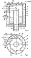
- the gas / liquid separator is now shown enlarged in FIGS. 3 to 5 in various views. It consists essentially of a cyclone housing, generally designated 24, into which a cylindrical inner housing 33 is inserted, in which, with the help of Leit sheet 36 a potential vortex is generated.
- the result is a two-stage centrifugal separator, the first stage of which works on the principle of the cyclone separator and the second stage of which works as a potential vortex separator.
- the cyclone separator has a cylindrical jacket 25 with a cover 26 and a bottom 27. On the jacket 25 there is a tangential feed 28 for the gas-liquid mixture coming from the vacuum pump, as well as a nozzle 29 through which the heated operating liquid to be discharged corresponding to the quantity of fresh liquid supplied is discharged. If water is the operating liquid, it can be discharged from there directly into the sewage system or, for other liquids, into a cooling and treatment plant for reuse.
- the potential vortex separator is formed by the cylindrical inner housing 33.
- the gas-liquid mixture largely freed of liquid in the cyclone separator is discharged from the annular space 37 of the cyclone separator via that at the upper part of the separator below the cover 26 attached guide plates 36 through the upper opening 35 of the inner housing 33 into the interior 38 of this housing, a potential vortex being formed in this space by the guide plates 36, which leads to further separation of the gas from the liquid.
- the liquid runs down the inner wall and unites, since the cylindrical inner housing has a lower opening 34, with the liquid from the cyclone separator which is already there.
- the temperature sensor designed as an immersion temperature sensor 40, is expediently attached to the base 27 of the gas-liquid separator.
- a particularly compact design can be achieved if the coolant line 15 and the control valve designed as a solenoid valve with presetting 14 are attached directly to the separator.
- FIG. 6 Such an arrangement is indicated in a schematic representation in FIG. 6.
- This illustration also shows the possible arrangement of the ventilation line 23 and the operating liquid line 19 with control elements on or in the gas / liquid separator 11.
Abstract
Description
Die Erfindung betrifft eine Anordnung zur Minimierung des Kühlflüssigkeitsverbrauches, sowie gegebenenfalls zur Verhinderung von Kavitation, insbesondere bei Flüssigkeitsring-Vakuumpumpen oder dergl.The invention relates to an arrangement for minimizing the consumption of cooling liquid and, if appropriate, for preventing cavitation, in particular in the case of liquid ring vacuum pumps or the like.
Das Saugvermögen einer Flüssigkeitsring-Vakuumpumpe hängt außer vom Fördermedium in erheblichem Maße von der Betriebsflüssigkeit ab und zwar bei dem überwiegend verwendeten Wasser als Betriebsflüssigkeit von dessen Temperatur. Das Saugvermögen einer Wasserring-Vakuumpumpe kann durch die Verstellung der Temperatur des Betriebswassers insbesondere im Bereich höherer Unterdrücke stark beeinflußt werden, wobei eine geringere Betriebsflüssigkeitstemperatur höhere Leistungen erbringt. Damit ergibt sich das Erfordernis einer Kühlung der umlaufenden Betriebsflüssigkeit, was bei Wasser als Betriebsflüssigkeit in der Regel dadurch geschieht, daß aus dem Betriebsflüssigkeitskreislauf immer ein Teil der erwärmten Flüssigkeit abgeführt und durch kühlere Frischflüssigkeit aus dem Leitungsnetz ersetzt wird, d.h. der Betrieb einer Wasserring-Vakuumpumpe macht immer einen mehr oder weniger großen Frischwasserverbrauch erforderlich, der die Betriebskosten einer solchen Pumpe oft nicht unerheblich belastet.The pumping speed of a liquid ring vacuum pump depends not only on the medium to be pumped, but also to a considerable extent on the operating liquid, and in the case of the predominantly used water as operating liquid on its temperature. The pumping speed of a water ring vacuum pump can be greatly influenced by adjusting the temperature of the process water, particularly in the region of higher negative pressures, with a lower operating liquid temperature providing higher outputs. This results in the need to cool the circulating operating fluid, which usually happens with water as the operating fluid in that part of the heated fluid is always removed from the operating fluid circuit and replaced by cooler fresh fluid from the supply network, i.e. the operation of a water ring vacuum pump always requires a more or less high consumption of fresh water, which often has a considerable impact on the operating costs of such a pump.
Durch die vorliegende Erfindung soll deshalb die Aufgabe gelöst werden, eine Senkung der Wasserbetriebskosten insbes. für Wasserring-Vakuumpumpen zu erreichen. Eine solche Senkung der Betriebskosten gilt natürlich auch für andere Betriebsflüssigkeiten als Wasser, da diese ja auch in einem internen Kühlkreislauf mit hohem Aufwand immer wieder heruntergekühlt werden mußten.The object of the present invention is therefore to achieve a reduction in the water operating costs, in particular for water ring vacuum pumps. Such Lowering the operating costs naturally also applies to operating fluids other than water, since these had to be cooled down again and again with great effort in an internal cooling circuit.
Zur Lösung der gestellten Aufgabe wird erfindungegemäß bei einer Anordnung der eingangs genannten Art vorgeschlagen, in der Abgasleitung der Flüssigkeitsring-Vakuumpumpe einen als ein- oder mehrstufigen Gas-/Flüssigkeits-Separator ausgebildeten Abscheidebehälter mit einem Temperatur-Meßwertaufnehmer im Behälter oder in der Umlaufleitung der Abgasleitung oder der Vakuumpumpe für die Betriebsflüssigkeitemperatur der Flüssigkeitsring-Vakuumpumpe anzuordnen, der über eine Steuereinrichtung mit einem Stellventil in der Kühlfiüssigkeitsleitung verbunden ist,To achieve the object, according to the invention, in an arrangement of the type mentioned at the outset, a separating container designed as a single-stage or multi-stage gas / liquid separator with a temperature sensor in the container or in the circulation line of the exhaust gas line is designed in the exhaust line of the liquid ring vacuum pump or to arrange the vacuum pump for the operating fluid temperature of the fluid ring vacuum pump, which is connected via a control device to a control valve in the cooling fluid line,
In einfachster Ausgestaltung der Erfindung können dabei der Temperatur-Meßwertaufnehmer als Thermostatregler und das Stellventil als Magnetventil ausgebildet oder auch durch ein manuell betätigtes Ventil ersetzt sein.In the simplest embodiment of the invention, the temperature sensor can be designed as a thermostat and the control valve as a solenoid valve or can also be replaced by a manually operated valve.
Vorteilhaft soll aber der Temperatur-Meßwertaufnehmer über ein Steuergerät, welches einen oder mehrere Ein- und Ausginge. sowie zeitliche und logische Verknüpfungen für eine speicherprogrammierbare Steuerung aufweist, mit dem Stellventil in der Kühlflüssigkeitsleitung verbunden sein.However, the temperature sensor should be advantageous via a control unit which has one or more inputs and outputs. and also has temporal and logical links for a programmable logic controller to be connected to the control valve in the coolant line.
Bei einer bevorzugten Ausführungsform der Erfindung soll der Gas-/Flüssigkeits-Separator als zweistufiger Fliehkraftabscheider ausgebildet sein, bei dem die erste Stufe ein Zyklonabscheider und die zweite Stufe ein Potentialwirbelabscheider ist. Dabei soll der Zyklonabscheider aus einem Gehäuse mit einem zylindrischen Mantel bestehen, an dem eine tangentiale Zuleitung für das Gas-Flüssigkeits-gemisch und eine Ableitung für die abgeführte Flüssigkeit angebracht sind. Das Gehäuse soll einen geschlossenen Deckelteil und einen Bodenteil aufweisen, an dem eine Abführung für die Betriebsflüssigkeit angeordnet ist und durch den eine Leitung für die Ableitung des Gases aus dem Abscheider hindurchgeführt ist, deren Eintrittsöffnung oberhalb der Ableitung für die abgeführte Flüssigkeit liegt. Der Potentialwirbelabscheider soll als in das Gehäuse des Zyklonabscheiders eingesetztes zylindrisches Gehäuse ausgebildet sein, dessen untere öffnung im Abscheideraum für die Flüssigkeit unterhalb der Ableitung für die abgeleitete Flüssigkeit liegt und dessen obere öffnung mit dem Innenraum des Gehäuses durch Leitbleche in Verbindung steht, durch die die Strömung vom Innenraum des Zyklonabscheiders im wesentlichen tangential in den Innenraum des zylindrischen Gehäuses geleitet wird.In a preferred embodiment of the invention, the gas / liquid separator is designed as a two-stage centrifugal separator, in which the first stage is a cyclone separator and the second stage is a potential vortex separator. The cyclone separator should consist of a housing with a cylindrical jacket, to which a tangential feed line for the gas-liquid mixture and a discharge line for the discharged liquid are attached. The housing should have a closed cover part and a bottom part, on which a discharge for the operating liquid is arranged and through which a line for the discharge of the gas from the separator is passed, the inlet opening of which is above the discharge for the discharged liquid. The potential vortex separator should be designed as a cylindrical housing inserted into the housing of the cyclone separator, the lower opening of which is in the liquid separation space below the discharge line for the derived liquid and the upper opening of which is connected to the interior of the housing by baffles through which the flow from the interior of the cyclone separator is guided substantially tangentially into the interior of the cylindrical housing.
Der Temperatur-Meßwertaufnehmer kann als am Boden des Gas-/Flüssigkeits-Abscheiders angeordneter, in den Flüssigkeitsbereich des Abscheiders ragender Tauchtemperaturfühler bzw. Thermostat ausgebildet sein.The temperature transducer can be an immersion temperature arranged at the bottom of the gas / liquid separator and projecting into the liquid area of the separator sensor or thermostat.
Die Abführung für die Betriebsflüssigkeit soll niedriger liegen als die Zuführung der KühlflUssigkeit, so daß ein Rückfließen der Kühlflüssigkeit ausgeschlossen wird (Systemtrennung). Die KUhlflüssigkeitsleitung kann in den Saugraum bzw. das Saugrohr der Vakuumpumpe führen. Sie kann im Gas-Flüssigkeitsabscheider oder in der Abgasleitung mUnden.The discharge for the operating liquid should be lower than the supply of the cooling liquid, so that a backflow of the cooling liquid is excluded (system separation). The coolant line can lead into the suction chamber or the suction pipe of the vacuum pump. It can end in the gas-liquid separator or in the exhaust pipe.
In weiterer Ausgestaltung der Erfindung kann zur Vermeidung von Kavitation in der FlUssigkeitsring-Vakuumpumpe vom Gasraum des Gas-/Flüssigkeits-Abscheiders eine Leitung mit einstellbarem Gasdurchsatz, also z.B. mit einer Drossel in die Betriebsflüssigkeitsleitung geführt sein. Dabei entsteht durch Androsseln in der Betriebsflüssigkeitsleitung ein Unterdruck, durch den eine variable Gasmenge aus dem Separator der Vakuumpumpe durch einen Bypass zugeführt wird.In a further embodiment of the invention, in order to avoid cavitation in the liquid ring vacuum pump from the gas space of the gas / liquid separator, a line with adjustable gas throughput, e.g. be led into the operating fluid line with a throttle. Throttling in the operating fluid line creates a negative pressure, through which a variable amount of gas is fed from the separator to the vacuum pump through a bypass.
An Hand der beiliegenden Zeichnungen soll die Erfindung nachfolgend noch näher erläutert werden. Auf den Zeichnungen zeigen in schematischer Darstellung
- Fig. 1 den Gesamtaufbau einer erfindungsgemäßen Anordnung,
- Fig. 2 eine Anordnung zur Einleitung von Gas in die Betriebsflüssigkeitsleitung,
- Fig. 3 einen Vertikalschnitt durch ein Auführungsbeispiel eines zweistufigen Fliehkraftabscheiders,
- Fig. 4 eine Anischt von oben auf diesen Abscheider bei abgenommenem Deckelteil,
- Fig. 5 die Anordnung des Temperatur-Meßwertaufnehmers am Abscheider in Seitenansicht und
- Fig. 6 die Anordnung der Kühl flüssigkeitsleitung und des Stellventils am Abscheider in schematischer Darstellung.
- 1 shows the overall structure of an arrangement according to the invention,
- 2 shows an arrangement for introducing gas into the operating fluid line,
- 3 shows a vertical section through an exemplary embodiment of a two-stage centrifugal separator,
- 4 shows a mixture from above of this separator with the cover part removed,
- Fig. 5 shows the arrangement of the temperature sensor on the separator in side view
- Fig. 6 shows the arrangement of the cooling liquid line and the control valve on the separator in a schematic representation.
In den Figuren sind gleiche Teile mit gleichen Bezugszeichen versehen.In the figures, the same parts are provided with the same reference symbols.
Bei dem Gesamtaufbau einer Anordnung gemäß der Erfindung nach Fig. 1 ist die Flüssigkeitsring-Vakuumpumpe mit 10 bezeichnet, die durch die Vakuumleitung mit dem zu evakuierenden Raum verbunden ist. Die Pumpe 10 fördert ein Gas-Betriebsflüssigkeits-Gemisch durch die Leitung 22 in den Gas-/Flüssigkeitsabscheider 11, von dem ein Teil der abgeschiedenen Flüssigkeit durch die Leitung 20 abgeleitet und ein Teil durch die Betriebsflüssigkeitleitung 19 in die Vakuumpumpe zurückgeführt wird. Das von der Flüssigkeit getrennte Gas wird durch die Abgasleitung 21 abgeführt.In the overall structure of an arrangement according to the invention according to FIG. 1, the liquid ring vacuum pump is designated by 10, which is connected to the space to be evacuated by the vacuum line. The
Am Gas-/Flüssigkeits-Abscheider 11 ist ein Temperatur-Meßwertaufnehmer 12 angebracht, der im in Fig. 1 dargestellten Beispiel über das Steuergerät 13 mit einem Stellventil 14 mit Voreinstellung in der Frisch- oder Kühlwasserleitung 15 verbunden ist, wobei das Ventil so gesteuert wird, daß durch Zugabe von Kühlflüssigkeit die Temperatur der Betriebsflüssigkeit auf einen konstanten eingestellten Wert geregelt oder optimal für den jeweiligen Betriebspunkt der Pumpe eingestellt wird, was bedeutet, daß bei der optimalen Temperatur der Betriebsflüssigkeit beim Druckregelbetrieb des Vakuumsystems ein Minimum an Kühlflüssigkeit zugeführt wird.On the gas /
Am Abscheider 11 wird durch die Leitung 20 eine dieser zugeführten Frischflüssigkeitsmenge entsprechende Flüssigkeitsmenge abgeführt und ist ein Maß für den eigentlichen Flüssigkeitsverbrauch. Die Regel- und Steuerungsfunktionen übernimmt ein Micro-Computer im Schaltschrank 13.At the
In Fig. 2 ist die Kombination Meßwertaufnehmer 12, Schaltschrank 13, Stellventil 14 durch die technisch aber auch leistungsmißig einfachere und preisgünstigere Kombination Thermostatregler 17 und Stellventil 14 ersetzt, die für einfachere B-etriebsfälle oft ausreichend ist und jederzeit auf die in Fig. 1 dargestellte Kombination erweiterbar ist.In Fig. 2, the combination of
Außerdem ist in Fig. 2 noch eine einfache Anordnung zur Verhinderung von Kavitation in der Vakuumpumpe angedeutet. Dazu führt eine Belüftungsleitung 23 mit einstellb. Durchsatz vom Gasraum des Abssheiders 11 in die Betriebsflüssigkeitsleitung 19. Von hier gelangt die Luft bzw. das Gas dann in die Pumpe.In addition, a simple arrangement for preventing cavitation in the vacuum pump is indicated in FIG. 2. For this purpose, a
Der Gas-/Flüssigkeitsabscheider ist nun in den Fig. 3 bis 5 in verschiedenen Ansichten vergrößert dargestellt. Er besteht im wesentlichen aus einem allgemein mit 24 bezeichneten Zyklongehäuse, in das ein zylindrisches Innengehäuse 33 eingesetzt ist, in dem mit Hilft von Leitblechen 36 ein Potentionalwirbel erzeugt wird. Es entsteht so ein zweistufiger Fliehkraftabscheider, dessen erste Stufe nach dem Prinzip des Zyklonabscheiders und dessen zweite Stufe als Potentialwirbelabscheider arbeitet.The gas / liquid separator is now shown enlarged in FIGS. 3 to 5 in various views. It consists essentially of a cyclone housing, generally designated 24, into which a cylindrical
Der Zyklonabscheider weist einen zylindrischen Mantel 25 mit einem Deckel 26 und einem Boden 27 auf. AM Mantel 25 ist eine tangentiale Zuführung 28 für das aus der Vakuumpumpe kommende Gas-Flüssigkeits-Gemisch angebracht, sowie ein Stutzen 29, durch den die der zugeführten Frischflüssigkeitsmenge entsprechende Menge abzuleitender erwärmter Betriebsflüssigkeit abgeführt wird. Dabei kann bei Wasser als Betriebsflüssigkeit die Abführung von dort eventuell gleich in die Kanalisation erfolgen oder bei anderen Flüssigkeiten in eine Kühl- und Aufbereitungsanlage zur Wiederverwendung.The cyclone separator has a
Am Boden 27 ist einmal ein Ablauf 30 für das zur Pumpe zurückzuführende Betriebswasser angebracht und zum anderen eine leitung 31 zur Abführung des Gases deren Zulauföffnung 32 sich deshalb im Gasraum des Abscheiders befindet.On the
Der Potentialwirbelabscheider wird durch das zylindrische Innengehäuse 33 gebildet. Dabei wird das im Zyklon- abscheider weitgehend von Flüssigkeit befreite Gas-Flüssigkeits-Gemisch aus dem Ringraum 37 des Zyklon- abscheiders über die am oberen Teil des Abscheiders unterhalb des Deckels 26 angebrachten Leitbleche 36 durch die obere Öffnung 35 des Innengehäuses 33 in den Innenraum 38 dieses Gehäuses eingeführt, wobei sich durch die Leitbleche 36 in diesem Raum ein Potentialwirbel ausbildet, der zur weiteren Separierung des Gases von der Flüssigkeit führt. Die Flüssigkeit läuft dabei an der Innenwand herab und vereinigt sich, da das zylindrische Innengehäuse eine untere Öffnung 34 aufweist, mit der dort schon befindlichen Flüssgkeit aus dem Zyklonabscheider.The potential vortex separator is formed by the cylindrical
Wie Fig. 5 erkennen läßt, wird der als Tauchtemperaturfühler 40 ausgebildete Temperatur-Meßwertaufnehmer zweckmäßig am Boden 27 des Gas-Flüssigkeitsabscheider befestigt. Eine besonders kompa-kte Ausführung läßt sich erreichen, wenn die Kühlflüssigkeitsleitung 15 und das als Magnetventil mit Voreinstellung 14 ausgeführte Stellventil direkt am Abscheider angebracht sind.As can be seen in FIG. 5, the temperature sensor, designed as an
In Fig. 6 ist eine derartige Anordnung in schematischer Darstellung angedeutet. In dieser Darstellung sind auch die mögliche Anordnung der Belüftungsleitung 23 und der Betriebsflüssigkeitsleitung 19 mit Regelorganen am bzw, im Gas-/ Flüssigkeitsabscheider 11 wiedergegeben.Such an arrangement is indicated in a schematic representation in FIG. 6. This illustration also shows the possible arrangement of the
Claims (13)
Priority Applications (1)
| Application Number | Priority Date | Filing Date | Title |
|---|---|---|---|
| AT85108389T ATE70340T1 (en) | 1984-07-12 | 1985-07-05 | ARRANGEMENT TO MINIMIZE COOLANT CONSUMPTION, PARTICULARLY IN LIQUID RING VACUUM PUMPS OR THE LIKE. |
Applications Claiming Priority (2)
| Application Number | Priority Date | Filing Date | Title |
|---|---|---|---|
| DE19843425616 DE3425616A1 (en) | 1984-07-12 | 1984-07-12 | ARRANGEMENT TO MINIMIZE COOLANT CONSUMPTION IN PARTICULAR. FOR LIQUID RING VACUUM PUMPS OR THE LIKE. |
| DE3425616 | 1984-07-12 |
Publications (3)
| Publication Number | Publication Date |
|---|---|
| EP0174454A2 true EP0174454A2 (en) | 1986-03-19 |
| EP0174454A3 EP0174454A3 (en) | 1986-11-20 |
| EP0174454B1 EP0174454B1 (en) | 1991-12-11 |
Family
ID=6240416
Family Applications (1)
| Application Number | Title | Priority Date | Filing Date |
|---|---|---|---|
| EP85108389A Expired - Lifetime EP0174454B1 (en) | 1984-07-12 | 1985-07-05 | Installation for the minimalisation of cooling liquid consumption, especially for liquid ring vacuum pumps or similar pumps |
Country Status (8)
| Country | Link |
|---|---|
| US (1) | US4692101A (en) |
| EP (1) | EP0174454B1 (en) |
| JP (1) | JPS6140477A (en) |
| AT (1) | ATE70340T1 (en) |
| CA (1) | CA1268748A (en) |
| DE (2) | DE3425616A1 (en) |
| DK (1) | DK164134C (en) |
| NO (1) | NO166199C (en) |
Cited By (2)
| Publication number | Priority date | Publication date | Assignee | Title |
|---|---|---|---|---|
| EP0638723A1 (en) * | 1993-08-11 | 1995-02-15 | Siemens Aktiengesellschaft | Mechanical compressor |
| DE19715480A1 (en) * | 1997-04-14 | 1998-10-15 | Saskia Solar Und Energietechni | Vacuum pump system with a liquid ring pump |
Families Citing this family (13)
| Publication number | Priority date | Publication date | Assignee | Title |
|---|---|---|---|---|
| US4756672A (en) * | 1986-01-27 | 1988-07-12 | Siemens Aktiengesellschaft | Liquid-ring pump with maintenance of liquid level |
| US4699570A (en) * | 1986-03-07 | 1987-10-13 | Itt Industries, Inc | Vacuum pump system |
| DE3829263A1 (en) * | 1988-08-29 | 1990-03-15 | Schmitz Uwe | DEVICE FOR DISTRIBUTING A FLOWING LIQUID GAS MIXTURE IN MULTIPLE SUB-FLOWS |
| US4919826A (en) * | 1988-12-20 | 1990-04-24 | Air Techniques, Incorporated | Process and apparatus for separating solids and liquids from an effluent stream |
| US5584911A (en) * | 1995-06-15 | 1996-12-17 | Jordan Holding Company | Vapor recovery system with cyclonic separator |
| ATE285037T1 (en) * | 1998-03-19 | 2005-01-15 | Nsb Gas Proc Ag | METHOD AND SENSOR FOR DETECTING CAVITATIONS, AND DEVICE CONTAINING SUCH A SENSOR |
| DE19932632A1 (en) * | 1999-07-13 | 2001-02-01 | Siemens Ag | Two-stage fluid ring machine |
| FI110537B (en) * | 2001-06-29 | 2003-02-14 | Evac Int Oy | The vacuum sewer system |
| US6558131B1 (en) * | 2001-06-29 | 2003-05-06 | nash-elmo industries, l.l.c. | Liquid ring pumps with automatic control of seal liquid injection |
| US7465391B2 (en) * | 2005-09-09 | 2008-12-16 | Cds Technologies, Inc. | Apparatus for separating solids from flowing liquids |
| CN104066989B (en) * | 2011-12-14 | 2017-03-01 | 斯特林工业咨询有限公司 | For empty chamber and purify from described chamber extract gas apparatus and method |
| ZA201705612B (en) * | 2016-08-24 | 2018-08-29 | Gido Johan Fourie | A water saving device |
| CN112344215A (en) * | 2020-09-18 | 2021-02-09 | 南通新金丰皮革机械有限公司 | Vacuum system liquid feeding device for leather |
Citations (11)
| Publication number | Priority date | Publication date | Assignee | Title |
|---|---|---|---|---|
| US1681574A (en) * | 1923-03-01 | 1928-08-21 | Westinghouse Air Brake Co | Rotary compressor |
| DE689345C (en) * | 1935-11-17 | 1940-03-18 | Siemens Schuckertwerke Akt Ges | Method for creating a vacuum in a gl |
| US2195375A (en) * | 1935-12-30 | 1940-03-26 | Nash Engineering Co | Pump |
| CH284884A (en) * | 1950-09-15 | 1952-08-15 | Burckhardt Ag Maschf | Liquid ring pump. |
| US2971691A (en) * | 1955-08-16 | 1961-02-14 | Heraeus Gmbh W C | Pumping system |
| US3032258A (en) * | 1958-09-04 | 1962-05-01 | Nash Engineering Co | Vacuum pumps |
| FR1553943A (en) * | 1967-12-05 | 1969-01-17 | ||
| FR2180332A5 (en) * | 1972-04-08 | 1973-11-23 | Sihi Gmbh & Co Kg | |
| US3900300A (en) * | 1974-10-19 | 1975-08-19 | Universal Oil Prod Co | Vapor-liquid separation apparatus |
| DE3149802A1 (en) * | 1981-12-16 | 1983-07-21 | Bieger Apparate- Und Maschinenbau Kg, 6234 Hattersheim | Air separation and conveying device |
| DE3213155A1 (en) * | 1982-04-08 | 1983-10-13 | VIA Gesellschaft für Verfahrenstechnik mbH, 4000 Düsseldorf | Method for the monitoring of a compressed air generating system and device for carrying out the method |
Family Cites Families (17)
| Publication number | Priority date | Publication date | Assignee | Title |
|---|---|---|---|---|
| CA611354A (en) * | 1960-12-27 | R. Quertier John | Cooling system for air compressors | |
| US2057257A (en) * | 1933-10-23 | 1936-10-13 | Guy O Marchant | Method of and means for separating fluids |
| US2178994A (en) * | 1937-08-27 | 1939-11-07 | Clyde Paper Company Ltd | Centrifugal pump unit |
| US2230405A (en) * | 1938-04-20 | 1941-02-04 | Irving C Jennings | Pumping system |
| US3088595A (en) * | 1959-10-07 | 1963-05-07 | British Oxygen Co Ltd | Filter unit |
| FR1295617A (en) | 1961-05-09 | 1962-06-08 | Improvements to devices for purifying fluids loaded with solid particles | |
| US3877904A (en) | 1974-06-18 | 1975-04-15 | Combustion Eng | Gas-liquid separator |
| DE2460268B2 (en) * | 1974-12-19 | 1977-02-03 | Siemens AG, 1000 Berlin und 8000 München | LIQUID SEPARATOR |
| CA1038835A (en) * | 1974-12-27 | 1978-09-19 | General Signal Corporation | Low vacuum pumping system |
| US4050851A (en) * | 1975-11-10 | 1977-09-27 | The Nash Engineering Company | Liquid ring pumps and compressors using a ferrofluidic ring liquid |
| US4087208A (en) * | 1976-06-08 | 1978-05-02 | Mitsubishi Jukogyo Kabushiki Kaisha | Method for compressing mixed gas consisting of combustible gas and air |
| US4083658A (en) * | 1976-09-08 | 1978-04-11 | Siemens Aktiengesellschaft | Liquid ring compressor including a calibrated gas input opening |
| FR2374539A1 (en) * | 1976-12-15 | 1978-07-13 | Air Ind | WATER VAPOR COMPRESSION PROCESS, AND THERMAL CIRCUITS FOR ITS IMPLEMENTATION |
| US4151725A (en) * | 1977-05-09 | 1979-05-01 | Borg-Warner Corporation | Control system for regulating large capacity rotating machinery |
| DE3207507C2 (en) * | 1982-03-02 | 1984-12-20 | Siemens AG, 1000 Berlin und 8000 München | Liquid ring compressor |
| SU1041751A1 (en) | 1982-04-23 | 1983-09-15 | Предприятие П/Я В-8857 | Vacuum plant |
| DE3420144A1 (en) * | 1984-05-30 | 1985-12-05 | Loewe Pumpenfabrik GmbH, 2120 Lüneburg | CONTROL AND CONTROL SYSTEM, IN PARTICULAR. FOR WATERING VACUUM PUMPS |
-
1984
- 1984-07-12 DE DE19843425616 patent/DE3425616A1/en active Granted
-
1985
- 1985-07-05 DE DE8585108389T patent/DE3584863D1/en not_active Expired - Fee Related
- 1985-07-05 AT AT85108389T patent/ATE70340T1/en not_active IP Right Cessation
- 1985-07-05 CA CA000486384A patent/CA1268748A/en not_active Expired - Fee Related
- 1985-07-05 EP EP85108389A patent/EP0174454B1/en not_active Expired - Lifetime
- 1985-07-11 US US06/754,419 patent/US4692101A/en not_active Expired - Fee Related
- 1985-07-11 DK DK317685A patent/DK164134C/en not_active IP Right Cessation
- 1985-07-11 NO NO852787A patent/NO166199C/en unknown
- 1985-07-12 JP JP15257785A patent/JPS6140477A/en active Granted
Patent Citations (11)
| Publication number | Priority date | Publication date | Assignee | Title |
|---|---|---|---|---|
| US1681574A (en) * | 1923-03-01 | 1928-08-21 | Westinghouse Air Brake Co | Rotary compressor |
| DE689345C (en) * | 1935-11-17 | 1940-03-18 | Siemens Schuckertwerke Akt Ges | Method for creating a vacuum in a gl |
| US2195375A (en) * | 1935-12-30 | 1940-03-26 | Nash Engineering Co | Pump |
| CH284884A (en) * | 1950-09-15 | 1952-08-15 | Burckhardt Ag Maschf | Liquid ring pump. |
| US2971691A (en) * | 1955-08-16 | 1961-02-14 | Heraeus Gmbh W C | Pumping system |
| US3032258A (en) * | 1958-09-04 | 1962-05-01 | Nash Engineering Co | Vacuum pumps |
| FR1553943A (en) * | 1967-12-05 | 1969-01-17 | ||
| FR2180332A5 (en) * | 1972-04-08 | 1973-11-23 | Sihi Gmbh & Co Kg | |
| US3900300A (en) * | 1974-10-19 | 1975-08-19 | Universal Oil Prod Co | Vapor-liquid separation apparatus |
| DE3149802A1 (en) * | 1981-12-16 | 1983-07-21 | Bieger Apparate- Und Maschinenbau Kg, 6234 Hattersheim | Air separation and conveying device |
| DE3213155A1 (en) * | 1982-04-08 | 1983-10-13 | VIA Gesellschaft für Verfahrenstechnik mbH, 4000 Düsseldorf | Method for the monitoring of a compressed air generating system and device for carrying out the method |
Cited By (3)
| Publication number | Priority date | Publication date | Assignee | Title |
|---|---|---|---|---|
| EP0638723A1 (en) * | 1993-08-11 | 1995-02-15 | Siemens Aktiengesellschaft | Mechanical compressor |
| DE19715480A1 (en) * | 1997-04-14 | 1998-10-15 | Saskia Solar Und Energietechni | Vacuum pump system with a liquid ring pump |
| DE19715480C2 (en) * | 1997-04-14 | 1999-01-14 | Saskia Solar Und Energietechni | Vacuum pump system with a liquid ring pump |
Also Published As
| Publication number | Publication date |
|---|---|
| ATE70340T1 (en) | 1991-12-15 |
| DK164134C (en) | 1992-10-12 |
| CA1268748A (en) | 1990-05-08 |
| NO166199B (en) | 1991-03-04 |
| DK164134B (en) | 1992-05-11 |
| EP0174454A3 (en) | 1986-11-20 |
| DE3584863D1 (en) | 1992-01-23 |
| DK317685A (en) | 1986-01-13 |
| NO852787L (en) | 1986-01-13 |
| EP0174454B1 (en) | 1991-12-11 |
| NO166199C (en) | 1991-06-12 |
| DK317685D0 (en) | 1985-07-11 |
| DE3425616C2 (en) | 1988-12-15 |
| JPS6140477A (en) | 1986-02-26 |
| DE3425616A1 (en) | 1986-01-23 |
| US4692101A (en) | 1987-09-08 |
| JPS649473B2 (en) | 1989-02-17 |
Similar Documents
| Publication | Publication Date | Title |
|---|---|---|
| EP0174454A2 (en) | Installation for the minimalisation of cooling liquid consumption, especially for liquid ring vacuum pumps or similar pumps | |
| EP0635296B1 (en) | Filter for liquids | |
| WO1992022506A1 (en) | Process and device for purifying sewage | |
| EP1261809A1 (en) | Cooling device | |
| CH668162A5 (en) | METHOD FOR STERILIZING LIQUIDS, AND SYSTEM FOR IMPLEMENTING THE METHOD. | |
| DE3103842A1 (en) | SWIRL CHAMBER FILTERS FOR SEPARATING SOLIDS FROM A GAS FLOW | |
| DE2257054A1 (en) | TREATMENT METHODS OF SLUDGE AND LIQUIDS | |
| DE2400325A1 (en) | GENTLE COMPRESSOR WORKING WITH OIL INJECTION | |
| DE2530399A1 (en) | GAS PURIFICATION DEVICE | |
| PL310249A1 (en) | Apparatuis for separating liquids of different densities | |
| DE3210718A1 (en) | FLOW REGULATION DEVICE | |
| DE10243122A1 (en) | Self-cleaning filter arrangement | |
| DE3448123C2 (en) | Precipitator, in particular for liquid-ring vacuum pumps or the like | |
| DE914841C (en) | Device and method for directing a flow of liquid through several lines as a function of the viscosity | |
| DE3101954C2 (en) | ||
| DE2345637A1 (en) | Turbine with centrifugal stage(s) - has distributor duct(s), housing attached within turbine housing | |
| DE3439218A1 (en) | FAN | |
| DE3326326C2 (en) | ||
| DE3136647C2 (en) | Device for separating solids from a liquid flow, in particular from a power plant cooling water flow which is contaminated with solids | |
| DE60118178T2 (en) | METHOD AND APPARATUS FOR GUIDING THE CLEANED FIBER BREAK TO A CONTROLLED OUTPUT | |
| EP0735272B1 (en) | Centrifugal pump with venting | |
| AT413602B (en) | Apparatus for drying sewage sludge comprises drum drier fed with hot gas from burner via heat exchanger, dust separator downstream from drier being connected to condenser, from which gas is recirculated to burner | |
| DE3245901C2 (en) | Valve for regulating the cream concentration in a centrifuge for skimming milk | |
| DE3924550A1 (en) | HEAT EXCHANGER, ESPECIALLY HEAT EXCHANGER IN THE ENGINE COOLING CIRCUIT OF A MOTOR VEHICLE | |
| DE3229471A1 (en) | Cooling system for a rotating roller |
Legal Events
| Date | Code | Title | Description |
|---|---|---|---|
| PUAI | Public reference made under article 153(3) epc to a published international application that has entered the european phase |
Free format text: ORIGINAL CODE: 0009012 |
|
| AK | Designated contracting states |
Kind code of ref document: A2 Designated state(s): AT CH DE FR GB IT LI SE |
|
| PUAL | Search report despatched |
Free format text: ORIGINAL CODE: 0009013 |
|
| AK | Designated contracting states |
Kind code of ref document: A3 Designated state(s): AT CH DE FR GB IT LI SE |
|
| 17P | Request for examination filed |
Effective date: 19870209 |
|
| 17Q | First examination report despatched |
Effective date: 19880610 |
|
| RAP1 | Party data changed (applicant data changed or rights of an application transferred) |
Owner name: LOEWE PUMPENFABRIK GMBH |
|
| GRAA | (expected) grant |
Free format text: ORIGINAL CODE: 0009210 |
|
| AK | Designated contracting states |
Kind code of ref document: B1 Designated state(s): AT CH DE FR GB IT LI SE |
|
| PG25 | Lapsed in a contracting state [announced via postgrant information from national office to epo] |
Ref country code: SE Effective date: 19911211 Ref country code: IT Free format text: LAPSE BECAUSE OF FAILURE TO SUBMIT A TRANSLATION OF THE DESCRIPTION OR TO PAY THE FEE WITHIN THE PRESCRIBED TIME-LIMIT;WARNING: LAPSES OF ITALIAN PATENTS WITH EFFECTIVE DATE BEFORE 2007 MAY HAVE OCCURRED AT ANY TIME BEFORE 2007. THE CORRECT EFFECTIVE DATE MAY BE DIFFERENT FROM THE ONE RECORDED. Effective date: 19911211 Ref country code: FR Effective date: 19911211 |
|
| REF | Corresponds to: |
Ref document number: 70340 Country of ref document: AT Date of ref document: 19911215 Kind code of ref document: T |
|
| REF | Corresponds to: |
Ref document number: 3584863 Country of ref document: DE Date of ref document: 19920123 |
|
| GBT | Gb: translation of ep patent filed (gb section 77(6)(a)/1977) | ||
| EN | Fr: translation not filed | ||
| PLBE | No opposition filed within time limit |
Free format text: ORIGINAL CODE: 0009261 |
|
| STAA | Information on the status of an ep patent application or granted ep patent |
Free format text: STATUS: NO OPPOSITION FILED WITHIN TIME LIMIT |
|
| 26N | No opposition filed | ||
| PGFP | Annual fee paid to national office [announced via postgrant information from national office to epo] |
Ref country code: AT Payment date: 19930617 Year of fee payment: 9 |
|
| PGFP | Annual fee paid to national office [announced via postgrant information from national office to epo] |
Ref country code: CH Payment date: 19930705 Year of fee payment: 9 |
|
| PGFP | Annual fee paid to national office [announced via postgrant information from national office to epo] |
Ref country code: GB Payment date: 19930720 Year of fee payment: 9 |
|
| PGFP | Annual fee paid to national office [announced via postgrant information from national office to epo] |
Ref country code: DE Payment date: 19930804 Year of fee payment: 10 |
|
| PG25 | Lapsed in a contracting state [announced via postgrant information from national office to epo] |
Ref country code: GB Effective date: 19940705 Ref country code: AT Effective date: 19940705 |
|
| PG25 | Lapsed in a contracting state [announced via postgrant information from national office to epo] |
Ref country code: LI Effective date: 19940731 Ref country code: CH Effective date: 19940731 |
|
| GBPC | Gb: european patent ceased through non-payment of renewal fee |
Effective date: 19940705 |
|
| REG | Reference to a national code |
Ref country code: CH Ref legal event code: PL |
|
| PG25 | Lapsed in a contracting state [announced via postgrant information from national office to epo] |
Ref country code: DE Effective date: 19960402 |