EP0174081A2 - Schraubenrotorkompressor oder -expansionsmaschine - Google Patents
Schraubenrotorkompressor oder -expansionsmaschine Download PDFInfo
- Publication number
- EP0174081A2 EP0174081A2 EP85305197A EP85305197A EP0174081A2 EP 0174081 A2 EP0174081 A2 EP 0174081A2 EP 85305197 A EP85305197 A EP 85305197A EP 85305197 A EP85305197 A EP 85305197A EP 0174081 A2 EP0174081 A2 EP 0174081A2
- Authority
- EP
- European Patent Office
- Prior art keywords
- rotor
- lobe
- female
- pitch circle
- male
- Prior art date
- Legal status (The legal status is an assumption and is not a legal conclusion. Google has not performed a legal analysis and makes no representation as to the accuracy of the status listed.)
- Granted
Links
Images

Classifications
-
- F—MECHANICAL ENGINEERING; LIGHTING; HEATING; WEAPONS; BLASTING
- F01—MACHINES OR ENGINES IN GENERAL; ENGINE PLANTS IN GENERAL; STEAM ENGINES
- F01C—ROTARY-PISTON OR OSCILLATING-PISTON MACHINES OR ENGINES
- F01C1/00—Rotary-piston machines or engines
- F01C1/08—Rotary-piston machines or engines of intermeshing engagement type, i.e. with engagement of co- operating members similar to that of toothed gearing
- F01C1/082—Details specially related to intermeshing engagement type machines or engines
- F01C1/084—Toothed wheels
Definitions
- This invention relates to screw rotor machines for compression or expansion of a working fluid, and more particularly, to improved screw rotor profiles.
- Screw rotor machines employable both for compression or expansion of an elastic working fluid have used asymmetric rotor profiles for improved efficiency of the compression or expansion process.
- the development of asymmetric screw rotor profiles is exemplified by U.S. patents nos: 3,423,017, 4,140,445, 4,435,139, 4,053,263, 4,109,362, 4,401,420 and 4,406,602.
- Screw rotor machines whether functioning as compressors or expanders, are formed normally of a cast or machined casing or housing bearing two parallel, laterally intersecting cylindrical bores opening at respective ends to high pressure and low pressure ports. Within the bores there are mounted for rotation inter-engaging helical screw rotors of the male and female type provided with helical lobes or lands and intervening grooves having wrap angles normally less than 300 degrees.
- the male rotor is a rotor in which each lobe and groove has at least its major portion located outside the pitch circle of the rotor and has two generally convex flanks located outside the pitch circle
- the female rotor comprises a rotor in which each lobe and groove has at least its major portion located inside the pitch circle of the rotor and has two generally concave flanks located inside the pitch circle of the rotor.
- the female rotor physically drive the male rotor.
- the female driving rotor may consist of six lobes, while the male driven rotor may constitute four lobes and thus be rotated at one-half greater speed.
- the majority of lobe action occurs in the arc of approach or behind the line of centers. That is, a particularly destructive type of lobe action, because the direction of sliding of one lobe surface on the other is towards the pitch diameters and results in a spreading force which opposes rotation.
- United States Patents 3,423,017; 4,140,445; 4,053,263; 4,109,362; 4,401,420 and 4,406,602 this condition exists.
- a primary object of the present invention to provide an improved helical screw rotary machine having rotor profiles which improve meshing conditions, minimize leakage paths in the compressor or expander, improve cutting conditions in the manufacture of the rotors, and wherein the requirement for laser or other localized hardening of the lobes in the vicinity of the pitch surfaces is substantially eliminated.
- the invention is directed to the particular profiles of both male and female helical screw rotors for screw rotor machines,such as compressors or expanders.
- the elongated formed female rotor is adapted for rotation about its central longitudinal axis and has a pitch circle centered on the axis and an outer diameter.
- a plurality of elongated helical lobes extend longitudinally of the rotor and circumferentially spaced about the pitch circle so as to provide intervening grooves therebetween forming addendum portions outside the pitch circle and dedendum portions inside the pitch circle.
- each of the lobes extends generally radially inwardly of the pitch circle and the profile on each of the lobes in a plane perpendicular to the axis has a tip portion and respective generally concave grooves leading and trailing flank portions extending intermediate said tip portion and a root portion of the respective adjacent groove.
- the lobes of the female rotor engage grooves of the male rotor defined by corresponding helical lobes of the male rotor with contact between the flank portions of the respective female and male rotors during rotation of one rotor relative to the other.
- the improvement resides in the profile of the trailing flank portion of the female rotor groove being defined by first and second circular arcs formed by first and second radii within the addendum and dedendum portions of the lobe, respectively, providing a smooth uninterrupted surface starting below the pitch circle and terminating at or near the outside diameter of the rotor with the point of tangency of the first and second radii occurring at a point of zero sliding with the male rotor on the pitch circle.
- the female rotor groove trailing flank portion facilitates female rotor drive of the male rotor, reduction in blow holes formed between the female and male screw rotors, minimizes spreading forces acting on the rotors opposing their rotation, and loading of bearings mounting the rotors for rotation about their axis.
- the respective centers for the two radii may lie inside the pitch circle for the female rotor.
- each female rotor lobe may be defined by a true circular arc swung from an offset circle centered on the female rotor axis, at the trailing side of the female lobe tip, forming a female rotor lobe sealing strip to materially reduce the blow hole area of the screw rotor machine.
- a lobe surface portion may be defined by a third circular arc extending from the addendum circular arc portion of the trailing flank of the female rotor lobe outer periphery subscribed by a third radius whose length is between zero and a length such that the center of the third radius lies on the pitch circle and wherein the third radius is within the addendum of the female rotor lobe on the trailing flank side and is tangent with the periphery of the rotor lobe and with the first circular arc forming the trailing flank portion within the addendum and whose point of tangency with that first circular arc is radially outside of the pitch circle.
- the invention has further application to a male rotor for such screw rotor machines in which the elongated formed male rotor is rotatable about a central longitudinal axis and has a pitch circle centered on the axis.
- a plurality of elongated helical lobes extend longitudinally of the male rotor and circumferentially spaced about the pitch circle so as to provide intervening grooves therebetween, and a major portion of each of the lobes extends generally radially outwardly from the pitch circle.
- the profile of each of the lobes in a plane perpendicular to the axis has a tip portion and respective generally convex leading and trailing flank portions extending intermediate the tip portion and the root portion of the respective adjacent grooves.
- the improvement resides in the male rotor lobe leading flank portion profile comprising solely first and second circular arcs including a first circular arc defined by a first radius which lies on a radial line through the rotor center at an offset angle to the male rotor lobe centerline in the direction of the trailing flank of the rotor lobe, creating a male rotor high crest or tip point adjacent to the lobe trailing side, minimizing leakage of gas and eliminating the necessity of a separate milling operation.
- the first circular arc has a radial drop in the direction of the lobe leading side and the high crest point forming a male rotor lobe sealing line with other points along the helix to minimize leakage of the working fluid to thereby eliminate the necessity of a separate seal machining operation and thus reducing the cost of producing the male rotor.
- the center of the first radius subscribing the first circular arc forming the male rotor lobe tip lies on a radial line through the rotor center at an offset angle and is inside the pitch circle, and the second circular arc is subscribed by a second radius whose center is inside the pitch circle and within the dedendum of the male rotor lobe.
- the point of tangency or blend of the second radius with the first radius occurs outside of the pitch circle, and the second circular arc defined by the second radius terminates inside the pitch circle within the dedendum of the male rotor lobe, resulting in highly effective sealing surfaces for said male rotor lobe with said female rotor groove and a female rotor groove having an increased swept volume resulting in more efficient compressor or expander operation while permitting the effective active pressure angle to be fine tuned.
- a lobe surface may be defined by a third circular arc subscribed by a third radius whose length is within the range of zero to five per cent of the male rotor outside diameter, and wherein the center of that third radius is within the lobe addendum and positioned such that the third radius is tangent to the trailing and leading flank surface portions at the intersection therewith of the circular arc subscribed by the third radius to facilitate rotor machine operation operating and/or cutting conditions and to provide flexibility to the rotor profile without adversely affecting compressor or expander efficiency.
- Such constructions produce inherent sealing strips for both the male and female rotors, smaller blowholes, and reduced wear while eliminating the need for surface hardening of contacting rotor surfaces.
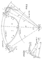
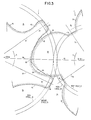
- FIGs 1 and 2 there are shown, in transverse section relative to the axis of the rotors, the profiles of a male helical screw rotor, indicated generally at 2, and a helical screw female rotor, indicated generally at 4 respectively. Further the profiles illustrate in Figure 1 a single complete male rotor lobe and, in Figure 2, female rotor lobes defining a groove therebetween. As may be appreciated, in customary practice, the profiles are described by outlining the method by which the profiles are developed over their complete exterior surface.
- the female rotor 4 drives male rotor 2, as per arrows 3 and 5, respectively, Figures 1 and 2.
- the outside diameter of the rotors and the center distance between the rotors which are intermeshed and which rotate within respective rotor bores (not shown) are defined.
- the pitch diameters of the male and female rotors 2, 4 are calculated, and the related root diameters are derived from the relationship to the outside diameters of the mating rotors.
- the pitch circle for the male rotor 2 is indicated at 10 and the root circle at 12.
- the pitch circle is indicated at 14 and the root circle at 16.
- the lobe thickness of the female rotor on the pitch circle is set at a predetermined value to provide suitable thermal conductivity and the necessary mechanical strength to avoid deformation or destruction under the forces of compression.
- the outside diameter circle is indicated at 18 for male rotor 2, and at 20 for female rotor 4.
- the radially projecting lobes or lands 22 of the male rotor 2 form grooves 26 therebetween.
- each male rotor lobe 22 comprises a lobe trailing flank 28 when the machine is functioning as a compressor, but which becomes the leading flank thereof when operating as an expander.
- each male rotor lobe is completed by a lobe leading flank 30, when the machine is functioning as a compressor or a trailing flank when the machine is functioning as an expander, respectively.
- the lobes 22 have a wrap angle of about 300 degrees.
- the female rotor 4 has its six helical lobes or lands 34 separated by the intervening grooves 36.
- the female rotor lobes 34 are provided with addendums 38 located radially outside of the pitch circle 14, while the male rotor has dedendums 32 located inside pitch circle 10 of that rotor.
- the female lobes are completed by dedendums 39, inside the pitch circle 14.
- Each female rotor groove 36 is formed by a groove trailing flank 40 of lobe 34 when the machine is functioning as a compressor and which becomes the leading flank when operating as an expander.
- To the opposite side of groove trailing flank 40 is groove leading flank 42 when the machine functions as a compressor which becomes a trailing flank when the machine functions as an expander.
- Each of the flanks 40, 42 extend from a radially innermost root portion bottom point "J" of groove 36 out to the crest portions 44 of respective adjacent lobes 34.
- each of the lobe flanks 28, 30 extend from a radially innermost bottom or root portion "A" of the male rotor groove 26 out to the crest point D of lobes 22.
- the present invention includes as a very important aspect of the rotor profile for the female rotor 4, the utilization of two radii partially defining the female groove trailing flank 40 to form a smooth uninterrupted surface of the trailing flank, running from a point N at the outside diameter 20 through the pitch circle 14 to point K.
- the first, M-N, of the two surface portions defined by these two radii extends in the form of a circular arc subscribed by a radius R 1 whose center of radius 45 lies inside the pitch circle 14.
- the second, groove trailing flank surface portion, K-M is created by subscribing an arc, via radius R 2 whose center 46 also lies inside the pitch circle 14.
- the effect of this is to provide a smooth uninterrupted convex surface portion by blending the circular arcs produced by the radii R 1 ,R 2 , with the point of tangency of both radii R , R 2 occurring at point M of "zero" sliding on the pitch circle 14. Further, the female groove trailing flank portion M-K smoothly blends with the male rotor generated surface portion J-K of trailing flank 40, at point K.
- the present invention is further characterized by the unique profile feature of the female lobe geometry N-H.
- the main lobe is not defined by a true radius swung from female rotor center 48.
- the main lobe surface portion N-H is a true radius swung from an offset circle 50, which offset circle is centered on the rotor center 48.
- the center 52 of radius R 3 is on the offset circle 50 to the groove trailing side of female lobe centerline 54.
- the center of radius R 3 subscribing the female lobe peripheral surface portion N-H, intersects the outside diameter 20 which is defined by a true radius R 4 from center 48 of the female rotor 4.
- the unique lobe or land crest portion 44 generates the root of the mating male rotor 2 with the result that a root groove is no longer necessary for the male rotor, such as groove 41 within the inventor's earlier United States Patent 4,053,263.
- This element of the cutting tool has long been a problem as it bcomes dull first and results in a tool which requires repeated sharpening.
- the main lobe periphery formed by surface portion N-H being defined by a circular arc swing from the offset circle 50 centered on the rotor center 48, at point 52, extends to both sides of the lobe centerline 54. As such, it is formed of two segments: a first segment or section from tip point N to lobe centerline 54, and a second segment from lobe centerline 54 to point H.
- sealing strip S is concentric to female rotor center 48.
- the part of the addendum 38, surface H-I, of the leading flank 42 is defined by a circular arc subscribed by radius R 55 whose center of radius 56 lies on pitch circle 14.
- the short female rotor groove leading flank addendum surface portion H-I, subscribed by radius R 52 is tangent to the offset lobe radius R 3 at point H, and the male rotor generated surface portion I-J of the trailing flank 42 at point I.
- the female rotor groove leading flank surface portion I-J is generated by the male rotor lobe tip radius subscribed leading flank surface portion D-E and further radius subscribed leading flank surface portion E-F.
- This generated surface portion I-J passes through groove 36 centerline 58, at point 60.
- the female rotor groove trailing flank 50 surface portion J-K of the female rotor 4 is also generated by the male rotor 2, specifically by male rotor lobe point D (or a D radius as a modification thereof).
- the female rotor lobe tip while illustrated in solid line in Figure 2 as a sharp point N, may be modified such that a small circular arc defines a corresponding surface area of female rotor lobe 34, depending on operating and/or cutting conditions for the rotor.
- an alternative lobe flank surface portion 62 formed by subscribing an arc via radius R 6 from a point 63 which is on the pitch circle 14.
- the minimum radius would be zero resulting in the formation of the sharp point N, while the maximum radius is one in which the center of radius R 6 is located on the pitch circle 14.
- the radius center 46 for radius R 2 is below the pitch circle 14 and that circular arc is tangent to the addendum portion M-N of trailing flank 40 at the pitch circle, point M.
- the radius R 1 is approximately twice the length of the dedendum radius R 2 and similarly is tangent with groove trailing flank surface portion K-M at the pitch circle 14.
- the male rotor lobes or lands 22 consist of male rotor lobe leading flank 30 and male rotor lobe trailing flank 28.
- Leading flank 30 begins at point D constituting the radial tip of each of the lands or lobes 22 on the outside diameter 18.
- the male tip and a significant portion of the leading flank 30 is defined by a circular arc D-E whose center is to the left of male rotor lobe centerline 72 and on a radial line 74 enamating from the rotor center 70 and intersecting the outside diameter 18 to define point D and forming a radial drop along the male rotor lobe leading flank 30.
- the lobe centerline 72 is located between the centerlines 76 for grooves 26 to each side of lobe 22.
- the location of the center 68 of the male tip radius R 7 is on radial line 74 through the rotor center 70, at an offset angle ⁇ , towards the trailing flank 28.
- the male rotor lobe tip radius R 7 is tangent to a second radius R 8 .
- the center 78 of radius R 8 lies below the pitch circle 10 with the point of tangency or blend point E of the two radii R 7 , R 8 occurring above the pitch circle 10.
- the center 78 of the second radius R 8 may be varied in size and/or position to result in higher or lower active pressure angles as required to fit cutting methods and conditions for the male rotor.
- radius R 8 is tangent to the tip radius R 7 at point E in the addendum 64 of the male rotor lobe or land 22, while radius R 8 is tangent to the tip radius R 7 at point E in the addendum 64 of the male rotor lobe or land 22, while radius R 8 is also tangent to male rotor lobe root surface portion F-G at point F, within the dedendum 32 of the male rotor lobe 22.
- Radii R 7 and R 8 combine with generally concave surface portions I-J of the female rotor groove leading flank, Figure 2, to provide highly efficient sealing surfaces therebetween, resulting in more efficient compressor or expander operation, while allowing the effective active pressure angle to be fine-tuned.
- the root surface portion F-G of the male rotor land or lobe 22 on the leading flank 30 side is subscribed by a radius R 9 , whose center 79 lies on the pitch circle 10.
- Male rotor lobe root surface portion G-A is generated by female rotor lobe surface portion N-H of the female rotor 4.
- the trailing flank surface portion A-B_ of the male rotor 2 is a trochoidal concave surface portion which is generated by either point N of the female rotor lobe 34 or an.equivalent N radius female rotor groove trailing flank surface portion of the female rotor (arc 62).
- the trailing flank surface portion B-C of the male rotor lobe 22 is generated by female rotor lobe addendum radius subscribed surface portion M-N on the female rotor lobe 34.
- the trailing flank major surface portion C-D is generated by the female lobe dedendum, radius subscribed, surface portion K-M of the groove trailing flank 40 of female rotor 4.
- male rotor 2 instead of having a sharp male tip point D, may have its rotor profile in this area modified to provide a small diameter circular arc over a portion of the surface where the trailing flank 28 merges with the leading flank 30.
- a radius equal to zero produces the sharp point D.
- that radius R 10 may be increased to a maximum of 5% of male rotor diameter.
- the maximum radius for R 10 enanate from a center point 80, the effect of which is to round off the surface of the male rotor lobe or land 22 in the vicinity of its outside diameter, and produce a circular arc indicated in dotted lines as at 82, Figure 1.
- the length of radius R10 depends on operating and/or cutting conditions to be met, thus providing flexibility to the design without measurably affecting compressor or expander efficiency.
- the profiles shown and described are reproducible over the wide range of rotor sizes employed in actual practice.
- the invention has application to intermeshed helical screw rotors, male or female driven, having a greater number or lesser number of lobes. Both rotors may have their pitch diameters, and center distances vary as needed.
Landscapes
- Engineering & Computer Science (AREA)
- Mechanical Engineering (AREA)
- General Engineering & Computer Science (AREA)
- Applications Or Details Of Rotary Compressors (AREA)
- Rotary Pumps (AREA)
- Supercharger (AREA)
- Details And Applications Of Rotary Liquid Pumps (AREA)
- Processing And Handling Of Plastics And Other Materials For Molding In General (AREA)
Priority Applications (1)
| Application Number | Priority Date | Filing Date | Title |
|---|---|---|---|
| AT85305197T ATE41201T1 (de) | 1984-08-31 | 1985-07-22 | Schraubenrotorkompressor oder expansionsmaschine. |
Applications Claiming Priority (2)
| Application Number | Priority Date | Filing Date | Title |
|---|---|---|---|
| US06/645,958 US4527967A (en) | 1984-08-31 | 1984-08-31 | Screw rotor machine with specific tooth profile |
| US645958 | 1984-08-31 |
Publications (3)
| Publication Number | Publication Date |
|---|---|
| EP0174081A2 true EP0174081A2 (de) | 1986-03-12 |
| EP0174081A3 EP0174081A3 (en) | 1986-03-26 |
| EP0174081B1 EP0174081B1 (de) | 1989-03-08 |
Family
ID=24591149
Family Applications (1)
| Application Number | Title | Priority Date | Filing Date |
|---|---|---|---|
| EP85305197A Expired EP0174081B1 (de) | 1984-08-31 | 1985-07-22 | Schraubenrotorkompressor oder -expansionsmaschine |
Country Status (6)
| Country | Link |
|---|---|
| US (1) | US4527967A (de) |
| EP (1) | EP0174081B1 (de) |
| JP (1) | JPS6161901A (de) |
| AT (1) | ATE41201T1 (de) |
| CA (1) | CA1247570A (de) |
| DE (1) | DE3568604D1 (de) |
Cited By (3)
| Publication number | Priority date | Publication date | Assignee | Title |
|---|---|---|---|---|
| EP0961009A3 (de) * | 1998-05-29 | 2000-09-06 | Carrier Corporation | Gepaartes Schraubenrotorprofil |
| US6296461B1 (en) | 1996-05-16 | 2001-10-02 | City University | Plural screw positive displacement machines |
| AU2003257923B2 (en) * | 1998-05-29 | 2006-09-14 | Carrier Corporation | Conjugate screw rotor profile |
Families Citing this family (17)
| Publication number | Priority date | Publication date | Assignee | Title |
|---|---|---|---|---|
| IN157732B (de) * | 1981-02-06 | 1986-05-24 | Svenska Rotor Maskiner Ab | |
| JPH0320481Y2 (de) * | 1985-06-29 | 1991-05-02 | ||
| US4673344A (en) * | 1985-12-16 | 1987-06-16 | Ingalls Robert A | Screw rotor machine with specific lobe profiles |
| US4671750A (en) * | 1986-07-10 | 1987-06-09 | Kabushiki Kaisha Kobe Seiko Sho | Screw rotor mechanism with specific tooth profile |
| JPS6463688A (en) * | 1987-09-01 | 1989-03-09 | Kobe Steel Ltd | Screw rotor for screw compressor |
| US4938672A (en) * | 1989-05-19 | 1990-07-03 | Excet Corporation | Screw rotor lobe profile for simplified screw rotor machine capacity control |
| US5066205A (en) * | 1989-05-19 | 1991-11-19 | Excet Corporation | Screw rotor lobe profile for simplified screw rotor machine capacity control |
| JP3356468B2 (ja) † | 1992-10-09 | 2002-12-16 | 株式会社前川製作所 | スクリューロータ |
| SE508087C2 (sv) * | 1996-12-16 | 1998-08-24 | Svenska Rotor Maskiner Ab | Par av samverkande skruvrotorer, skruvrotor samt skruvrotormaskin försedd med dylika skruvrotorer |
| JPH11141479A (ja) * | 1997-11-11 | 1999-05-25 | Kobe Steel Ltd | スクリュ式圧縮機等のスクリュロータ |
| US6193491B1 (en) * | 1999-12-22 | 2001-02-27 | Hong-Yih Cheng | Rotors for screw compressor |
| DE10327623B4 (de) * | 2003-06-19 | 2006-07-13 | Mtu Aero Engines Gmbh | Fräsverfahren zur Fertigung von Bauteilen |
| DE102006035782B4 (de) * | 2006-08-01 | 2018-10-25 | Gea Refrigeration Germany Gmbh | Schraubenverdichter für extrem große Betriebsdrücke |
| GB2512561B (en) * | 2012-12-12 | 2020-06-17 | Precision Tech Group Ptg Limited | Method of machining a rotor with variable-lead screw |
| DE102014105882A1 (de) | 2014-04-25 | 2015-11-12 | Kaeser Kompressoren Se | Rotorpaar für einen Verdichterblock einer Schraubenmaschine |
| CN113931837B (zh) * | 2021-10-12 | 2023-07-18 | 宿迁学院 | 一种具有内圆弧极限轮廓的易加工凸转子 |
| CN116608128B (zh) * | 2023-06-30 | 2025-09-05 | 西安交通大学 | 一种锥形干式螺杆真空泵转子结构及其设计方法 |
Family Cites Families (7)
| Publication number | Priority date | Publication date | Assignee | Title |
|---|---|---|---|---|
| GB1342287A (en) * | 1971-04-14 | 1974-01-03 | Kuehlautomat Veb | Rotor for screw-type compressors |
| BE792576A (fr) * | 1972-05-24 | 1973-03-30 | Gardner Denver Co | Rotor helicoidal de compresseur a vis |
| US4053263A (en) * | 1973-06-27 | 1977-10-11 | Joy Manufacturing Company | Screw rotor machine rotors and method of making |
| US4140445A (en) * | 1974-03-06 | 1979-02-20 | Svenka Rotor Haskiner Aktiebolag | Screw-rotor machine with straight flank sections |
| US4088427A (en) * | 1974-06-24 | 1978-05-09 | Atlas Copco Aktiebolag | Rotors for a screw rotor machine |
| US4210410A (en) * | 1977-11-17 | 1980-07-01 | Tokico Ltd. | Volumetric type flowmeter having circular and involute tooth shape rotors |
| SE429783B (sv) * | 1981-12-22 | 1983-09-26 | Sullair Tech Ab | Rotorer for en skruvrotormaskin |
-
1984
- 1984-08-31 US US06/645,958 patent/US4527967A/en not_active Expired - Lifetime
-
1985
- 1985-06-27 CA CA000485742A patent/CA1247570A/en not_active Expired
- 1985-07-09 JP JP60149372A patent/JPS6161901A/ja active Pending
- 1985-07-22 AT AT85305197T patent/ATE41201T1/de not_active IP Right Cessation
- 1985-07-22 DE DE8585305197T patent/DE3568604D1/de not_active Expired
- 1985-07-22 EP EP85305197A patent/EP0174081B1/de not_active Expired
Cited By (4)
| Publication number | Priority date | Publication date | Assignee | Title |
|---|---|---|---|---|
| US6296461B1 (en) | 1996-05-16 | 2001-10-02 | City University | Plural screw positive displacement machines |
| EP0961009A3 (de) * | 1998-05-29 | 2000-09-06 | Carrier Corporation | Gepaartes Schraubenrotorprofil |
| AU768287B2 (en) * | 1998-05-29 | 2003-12-04 | Carrier Corporation | Conjugate screw rotor profile |
| AU2003257923B2 (en) * | 1998-05-29 | 2006-09-14 | Carrier Corporation | Conjugate screw rotor profile |
Also Published As
| Publication number | Publication date |
|---|---|
| DE3568604D1 (en) | 1989-04-13 |
| JPS6161901A (ja) | 1986-03-29 |
| EP0174081A3 (en) | 1986-03-26 |
| ATE41201T1 (de) | 1989-03-15 |
| US4527967A (en) | 1985-07-09 |
| EP0174081B1 (de) | 1989-03-08 |
| CA1247570A (en) | 1988-12-28 |
Similar Documents
| Publication | Publication Date | Title |
|---|---|---|
| US4527967A (en) | Screw rotor machine with specific tooth profile | |
| USRE32568E (en) | Screw rotor machine and rotor profile therefor | |
| US3787154A (en) | Rotor profiles for helical screw rotor machines | |
| JPH0336121B2 (de) | ||
| KR910002727B1 (ko) | 양변위(positive-displacement) 회전장치 및 그 장치용의 로우터 | |
| EP0158514B1 (de) | Schraubenrotoren | |
| US4028026A (en) | Screw compressor with involute profiled teeth | |
| US4636156A (en) | Screw rotor machines with specific tooth profiles | |
| EP0961009B1 (de) | Gepaartes Schraubenrotorprofil | |
| EP0211514B1 (de) | Schraubenrotorengefüge aufweisende Rotationsmaschine | |
| US5782624A (en) | Fluid compression/expansion machine with fluted main rotor having ruled surface root | |
| EP0591979B2 (de) | Zahnprofil für Schraubenrotor | |
| US5624250A (en) | Tooth profile for compressor screw rotors | |
| US4321022A (en) | Inter-engaging threaded rotor and pinion machine with multi-edged pinion tooth flanks | |
| US4614484A (en) | Rotary screw compressor with specific tooth profile | |
| US20190323349A1 (en) | Screw rotor device | |
| US4673344A (en) | Screw rotor machine with specific lobe profiles | |
| US4671751A (en) | Screw rotor tooth profile | |
| US7163387B2 (en) | Meshing helical rotors | |
| US5417528A (en) | Method for making a wobblestick | |
| AU2003257923B2 (en) | Conjugate screw rotor profile | |
| EP3161261B1 (de) | Ein paar zusammenwirkender schraubenrotoren | |
| JPWO2004001229A1 (ja) | スクリュロータ |
Legal Events
| Date | Code | Title | Description |
|---|---|---|---|
| PUAI | Public reference made under article 153(3) epc to a published international application that has entered the european phase |
Free format text: ORIGINAL CODE: 0009012 |
|
| PUAL | Search report despatched |
Free format text: ORIGINAL CODE: 0009013 |
|
| AK | Designated contracting states |
Kind code of ref document: A2 Designated state(s): AT BE CH DE FR GB IT LI LU NL SE |
|
| AK | Designated contracting states |
Kind code of ref document: A3 Designated state(s): AT BE CH DE FR GB IT LI LU NL SE |
|
| 17P | Request for examination filed |
Effective date: 19860819 |
|
| 17Q | First examination report despatched |
Effective date: 19870218 |
|
| GRAA | (expected) grant |
Free format text: ORIGINAL CODE: 0009210 |
|
| AK | Designated contracting states |
Kind code of ref document: B1 Designated state(s): AT BE CH DE FR GB IT LI LU NL SE |
|
| PG25 | Lapsed in a contracting state [announced via postgrant information from national office to epo] |
Ref country code: NL Effective date: 19890308 Ref country code: LI Effective date: 19890308 Ref country code: CH Effective date: 19890308 Ref country code: BE Effective date: 19890308 Ref country code: AT Effective date: 19890308 |
|
| REF | Corresponds to: |
Ref document number: 41201 Country of ref document: AT Date of ref document: 19890315 Kind code of ref document: T |
|
| ITF | It: translation for a ep patent filed | ||
| REF | Corresponds to: |
Ref document number: 3568604 Country of ref document: DE Date of ref document: 19890413 |
|
| ET | Fr: translation filed | ||
| REG | Reference to a national code |
Ref country code: CH Ref legal event code: PL |
|
| PG25 | Lapsed in a contracting state [announced via postgrant information from national office to epo] |
Ref country code: LU Free format text: LAPSE BECAUSE OF NON-PAYMENT OF DUE FEES Effective date: 19890731 |
|
| NLV1 | Nl: lapsed or annulled due to failure to fulfill the requirements of art. 29p and 29m of the patents act | ||
| PLBE | No opposition filed within time limit |
Free format text: ORIGINAL CODE: 0009261 |
|
| STAA | Information on the status of an ep patent application or granted ep patent |
Free format text: STATUS: NO OPPOSITION FILED WITHIN TIME LIMIT |
|
| 26N | No opposition filed | ||
| PGFP | Annual fee paid to national office [announced via postgrant information from national office to epo] |
Ref country code: SE Payment date: 19910618 Year of fee payment: 7 |
|
| PGFP | Annual fee paid to national office [announced via postgrant information from national office to epo] |
Ref country code: GB Payment date: 19910712 Year of fee payment: 7 |
|
| PGFP | Annual fee paid to national office [announced via postgrant information from national office to epo] |
Ref country code: FR Payment date: 19910724 Year of fee payment: 7 |
|
| ITTA | It: last paid annual fee | ||
| PG25 | Lapsed in a contracting state [announced via postgrant information from national office to epo] |
Ref country code: GB Effective date: 19920722 |
|
| PG25 | Lapsed in a contracting state [announced via postgrant information from national office to epo] |
Ref country code: SE Effective date: 19920723 |
|
| GBPC | Gb: european patent ceased through non-payment of renewal fee |
Effective date: 19920722 |
|
| PG25 | Lapsed in a contracting state [announced via postgrant information from national office to epo] |
Ref country code: FR Effective date: 19930331 |
|
| REG | Reference to a national code |
Ref country code: FR Ref legal event code: ST |
|
| EUG | Se: european patent has lapsed |
Ref document number: 85305197.7 Effective date: 19930204 |
|
| PGFP | Annual fee paid to national office [announced via postgrant information from national office to epo] |
Ref country code: DE Payment date: 20030929 Year of fee payment: 19 |
|
| PG25 | Lapsed in a contracting state [announced via postgrant information from national office to epo] |
Ref country code: DE Free format text: LAPSE BECAUSE OF NON-PAYMENT OF DUE FEES Effective date: 20050201 |