EP0173772A2 - Extruder for foamed liquids - Google Patents
Extruder for foamed liquids Download PDFInfo
- Publication number
- EP0173772A2 EP0173772A2 EP84201289A EP84201289A EP0173772A2 EP 0173772 A2 EP0173772 A2 EP 0173772A2 EP 84201289 A EP84201289 A EP 84201289A EP 84201289 A EP84201289 A EP 84201289A EP 0173772 A2 EP0173772 A2 EP 0173772A2
- Authority
- EP
- European Patent Office
- Prior art keywords
- bypass
- passageway
- outfeed
- block
- extruder
- Prior art date
- Legal status (The legal status is an assumption and is not a legal conclusion. Google has not performed a legal analysis and makes no representation as to the accuracy of the status listed.)
- Granted
Links
Images


Classifications
-
- B—PERFORMING OPERATIONS; TRANSPORTING
- B29—WORKING OF PLASTICS; WORKING OF SUBSTANCES IN A PLASTIC STATE IN GENERAL
- B29C—SHAPING OR JOINING OF PLASTICS; SHAPING OF MATERIAL IN A PLASTIC STATE, NOT OTHERWISE PROVIDED FOR; AFTER-TREATMENT OF THE SHAPED PRODUCTS, e.g. REPAIRING
- B29C44/00—Shaping by internal pressure generated in the material, e.g. swelling or foaming ; Producing porous or cellular expanded plastics articles
- B29C44/34—Auxiliary operations
- B29C44/36—Feeding the material to be shaped
- B29C44/46—Feeding the material to be shaped into an open space or onto moving surfaces, i.e. to make articles of indefinite length
- B29C44/461—Feeding the material to be shaped into an open space or onto moving surfaces, i.e. to make articles of indefinite length dispensing apparatus, e.g. dispensing foaming resin over the whole width of the moving surface
- B29C44/462—Feeding the material to be shaped into an open space or onto moving surfaces, i.e. to make articles of indefinite length dispensing apparatus, e.g. dispensing foaming resin over the whole width of the moving surface provided with pre-foaming devices
-
- B—PERFORMING OPERATIONS; TRANSPORTING
- B29—WORKING OF PLASTICS; WORKING OF SUBSTANCES IN A PLASTIC STATE IN GENERAL
- B29C—SHAPING OR JOINING OF PLASTICS; SHAPING OF MATERIAL IN A PLASTIC STATE, NOT OTHERWISE PROVIDED FOR; AFTER-TREATMENT OF THE SHAPED PRODUCTS, e.g. REPAIRING
- B29C44/00—Shaping by internal pressure generated in the material, e.g. swelling or foaming ; Producing porous or cellular expanded plastics articles
- B29C44/34—Auxiliary operations
- B29C44/36—Feeding the material to be shaped
- B29C44/46—Feeding the material to be shaped into an open space or onto moving surfaces, i.e. to make articles of indefinite length
- B29C44/50—Feeding the material to be shaped into an open space or onto moving surfaces, i.e. to make articles of indefinite length using pressure difference, e.g. by extrusion or by spraying
- B29C44/507—Feeding the material to be shaped into an open space or onto moving surfaces, i.e. to make articles of indefinite length using pressure difference, e.g. by extrusion or by spraying extruding the compound through an annular die
-
- B—PERFORMING OPERATIONS; TRANSPORTING
- B29—WORKING OF PLASTICS; WORKING OF SUBSTANCES IN A PLASTIC STATE IN GENERAL
- B29C—SHAPING OR JOINING OF PLASTICS; SHAPING OF MATERIAL IN A PLASTIC STATE, NOT OTHERWISE PROVIDED FOR; AFTER-TREATMENT OF THE SHAPED PRODUCTS, e.g. REPAIRING
- B29C48/00—Extrusion moulding, i.e. expressing the moulding material through a die or nozzle which imparts the desired form; Apparatus therefor
- B29C48/03—Extrusion moulding, i.e. expressing the moulding material through a die or nozzle which imparts the desired form; Apparatus therefor characterised by the shape of the extruded material at extrusion
- B29C48/06—Rod-shaped
-
- B—PERFORMING OPERATIONS; TRANSPORTING
- B29—WORKING OF PLASTICS; WORKING OF SUBSTANCES IN A PLASTIC STATE IN GENERAL
- B29C—SHAPING OR JOINING OF PLASTICS; SHAPING OF MATERIAL IN A PLASTIC STATE, NOT OTHERWISE PROVIDED FOR; AFTER-TREATMENT OF THE SHAPED PRODUCTS, e.g. REPAIRING
- B29C48/00—Extrusion moulding, i.e. expressing the moulding material through a die or nozzle which imparts the desired form; Apparatus therefor
- B29C48/25—Component parts, details or accessories; Auxiliary operations
- B29C48/30—Extrusion nozzles or dies
- B29C48/305—Extrusion nozzles or dies having a wide opening, e.g. for forming sheets
-
- B—PERFORMING OPERATIONS; TRANSPORTING
- B29—WORKING OF PLASTICS; WORKING OF SUBSTANCES IN A PLASTIC STATE IN GENERAL
- B29C—SHAPING OR JOINING OF PLASTICS; SHAPING OF MATERIAL IN A PLASTIC STATE, NOT OTHERWISE PROVIDED FOR; AFTER-TREATMENT OF THE SHAPED PRODUCTS, e.g. REPAIRING
- B29C48/00—Extrusion moulding, i.e. expressing the moulding material through a die or nozzle which imparts the desired form; Apparatus therefor
- B29C48/25—Component parts, details or accessories; Auxiliary operations
- B29C48/36—Means for plasticising or homogenising the moulding material or forcing it through the nozzle or die
- B29C48/50—Details of extruders
- B29C48/72—Feedback means, i.e. part of the molten material being fed back into upstream stages of the extruder
-
- B—PERFORMING OPERATIONS; TRANSPORTING
- B29—WORKING OF PLASTICS; WORKING OF SUBSTANCES IN A PLASTIC STATE IN GENERAL
- B29C—SHAPING OR JOINING OF PLASTICS; SHAPING OF MATERIAL IN A PLASTIC STATE, NOT OTHERWISE PROVIDED FOR; AFTER-TREATMENT OF THE SHAPED PRODUCTS, e.g. REPAIRING
- B29C48/00—Extrusion moulding, i.e. expressing the moulding material through a die or nozzle which imparts the desired form; Apparatus therefor
- B29C48/03—Extrusion moulding, i.e. expressing the moulding material through a die or nozzle which imparts the desired form; Apparatus therefor characterised by the shape of the extruded material at extrusion
Definitions
- This invention relates to foamed liquids, and more particularly to an extruder by which foamed glue selectively is delivered to an elongated orifice assembly for extrusion onto a substrate surface, or is bypassed to a defoamer for recycling when extrusion is not taking place.
- U.S. Patent No. 4,258,088 describes the desirability of maintaining constant pressure of foamed glue at an elongated extruder orifice, whether glue is being extruded or being bypassed to a defoamer for recycling during periods when extrusion is not occurring. This is achieved in the patent by coupling the output conduit of the foamer through a control valve selectively to a foam infeed conduit leading to the extruder nozzle, or to a foam bypass conduit leading to the defoamer, and dimensioning the foam infeed conduit androzzle assembly, on the one hand, and the bypass conduit on the other hand, to have the same resistance to flow.
- Patent No. 3,965,860 discloses an elongated extruder in which a plurality of longitudinally spaced nozzles are supplied from a common elongated chamber coupled to a foam infeed conduit.
- the foamed liquid extruder of this invention incorporates in a unitary structure an elongated control valve assembly which functions in a foam extruding position of adjustment to couple an elongated outlet orifice assembly tb the inner end of an elongated infeed passageway assembly made up of a plurality of passageways all of which extend substantially equal distances from the orifice assembly to a foam infeed conduit, and in a bypass position of adjustment to couple the inner end of the infeed passageway assembly to the inner end of a foam bypass passageway assembly preferably made upof a plurality of passageways all of which extend substantially equal distances from their inner ends to a foam bypass conduit.
- Another object of this invention is to provide a foamed glue extruder of the class described which insures the extrusion of foam uniformly from the entire length of the outlet orifice assembly.
- Still another object of this invention is the provision of a foamed glue extruder of the class described in which a minimum of foamed glue is retained in the outlet orifice assembly during the period of bypassing of foamed glues for recycling.
- a further object of this invention is to provide a foamed glue extruder of the class described which is of simplified construction for economical manufacture, which is capable of being disassembled for cleaning with speed and facility and which requires minimum maintenance and repair.
- a still further object of this invention is to provide a foamed glue extruder of the class described - which may be incorporated into a variety of types of systems involving the application of foamed glues to various types of substrates.
- Another object of this invention is to provide a foamed glue extruder of the class described in which the outfeed through a laterally elongated outlet orifice assembly is controlled by a novel valve construction.
- a substrate 10 supported on an intermittently movable conveyor 12.
- the illustrated system has particular utility in the application of foamed glue to veneers in the production of plywood, it will be understood that it is applicable to the distribution of various foamed liquids over the surfaces of a wide variety of types of substrates.
- Fig. 5 also illustrates a reservior ' 14 for storing liquid glue for delivery, as by means of a constant volume flow pump (not shown) through a conduit to a liquid glue foamer 16. Air, nitrogen, or other gas under pressure also is delivered to.the foamer from a suitable source 18 of supply. Foamed glue produced at the foamer is delivered through conduit 20 to the extruder 22 of this invention.
- Conduit 20 communicates with the outer end of an infeed passageway assembly 24 for delivery of foamed glue from its inner end through a multiplicity of coupling ports 26 either to an outlet orifice assembly 28 or to a bypass passageway assembly 30.
- This selection is afforded by a selector valve 32 actuated by a controller 34.
- Foamed glue delivered through the orifice assembly is deposited upon a substrate only during those periods of time of movement of the substrate.
- the controller actuates the selector valve to divert the foamed glue to the bypass passageway . assembly from which it is returned through bypass conduit 36 to a defoamer 38 and thence through return conduit 40 to the storage reservoir 14.
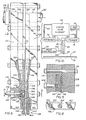
- Fig. 1 the extruder 22 is shown to include three elongated flat blocks; namely, infeed block 42, bypass block 44 and central coupling block 46. These blocks are secured together detachably in face-abutting relationship by means of bolts 48.
- infeed block 42 The inner surface of infeed block 42 is recessed to form an infeed passageway assembly 24 of a plurality of passageways.
- all of these passageways extend substantially equal distances from the connection of the foam inlet conduit 20 to the coupling port 26 in the center block 46.
- the inlet conduit is coupled to an infeed port 50 which communicates with the central point of an elongated main passageway 52.
- Each of the opposite outer ends of this main passageway communicates with the central point of a secondary passageway 54.
- Each of the opposite outer ends of each secondary passageway communicates with the inner end of a tertiary passageway 56.
- each of the opposite outer ends of each tertiary passageway communicates with the inner of a distribution passageway 58.
- Each distribution passageway 58 is triangular in plan view (Fig. 3). Although each passageway 58 may be of uniform dimension in transverse section, it preferably is triangular, as shown in Fig. 1. In this form it is also of maximum width, in transverse section, at its inner end, tapering to narrower width in transverse section at its outer end where it communicates with a plurality of the coupling ports 26 in the center block 46. For this purpose the distribution passageway is of maximum width in plan at its outer end, tapering to narrower width at its inner end. These dimensions preferably are chosen so that the longitudinal cross-sectional area of the distribution passageway remains substantially constant from the outer end to the inner end. It is by this means that there is achieved substantially uniform delivery of foamed glue through all of the coupling ports 26.
- the ends of the coupling ports 26 opposite the distribution passageway 58 communicate with longitudinally elongated valve chamber 60.
- This chamber is formed as a recess in the surface of bypass block 44 facing the central block 46.
- the upper end of.the valve chamber communicates with the wide inner ends of collector passageways 62.
- These collector passageways are constructed in the manner of the distribution passageway 58, but function to receive bypassed foamed glue for return to the reservoir 14, preferably through defoamer 38.
- the inner ends of adjacent pairs of collector passageways 62 are connected to the opposite ends of tertiary bypass passageways 64.
- Communicating with the central point of adjacent pairs of tertiary bypass passageways 64 are the opposite ends of secondary bypass passageways 66.
- Communicating with the central point of adjacent pairs of secondary bypass passageways are the opposite ends of a main bypass passageway 68.
- the central point of the main bypass passageway communicates with bypass port 70 which connects with bypass conduit 36.
- Valve chamber 60 contains elongated, C-shaped valve body 72 which is secured removably therein by means of bolts (not shown) extended through openings in the bypass block 44.
- bolts not shown
- Within the cavity of the valve body are three elongated, parallel clamp bars 74, 76 and 78. These clamp bars are of trapezoidal shape in cross section, the central bar 78 having its shorter side facing away from the center block 46 and the outer bars 74 and 76 having their shorter sides facing the center block.
- the outer bars 74 and 76 mount elongated, C-shaped valve members 80 and 82, respectively, These valve members are made of rubber or other suitably elastic material. Each has inwardly angles, longitudinally elongated lugs 84 on their terminal edges arranged to engage elongated notches 86 on the outward edges of the clamp bars.
- the outer clamp bars are secured to the valve body 72 by means of bolts 88, and the central bar 78 is secured between the outer bars by bolts 90.
- the central bar thus wedges between the outer bars and clamps the inner sides of the valve members 80 and 82 between them.
- the outer sides of the valve members are clamped between the bars and the confronting inner sides of the legs of the C-shaped body 72.
- closure bars 92 are interposed between the valve members and the central block 46. They are provided with smoothly contoured inner ends 92' which allow flexing of the elastic valve members with minimum fatigue. The valve members thus are afforded a long operating life.
- each valve member 80 and 82 is interposed between the inwardly facing side of the associated clamp bars 74 and 76, respectively, and the inner portion of the valve chamber 60 defined by the confronting surface of the central block 46.
- Each of the bars is provided with a transverse port 94 which is connected to a conduit 96 extending outwardly through the bypass block 44 for connection to the controller 34 (Fig.5).
- the controller includes a source of fluid under pressure, preferably air pressure, and a selector valve by which air pressure is delivered selectively to the valve members 80 and 82.
- Fig. 1 illustrates the condition in which air under pressure is delivered to valve member 80 to extend its central portion into sealing contact with the confronting surface of central block 46. Coupling ports 26 thus are communicated through valve chamber 60 and past retracted valve member 82 to the collector passageways 62.
- valve chamber 60 on the side of valve member 80 opposite the coupling port 26 communicates with outlet orifice assembly 28 through outfeed passageway 98.
- this assembly includes an elongated orifice block 100 provided with a multiplicity of longitudinally spaced apart orifices 102. As illustrated, these orifices are fitted with tubular orifice inserts 104 which project outwardly beyond the outer side of the block 100 to produce discrete extrusions of foamed glue. Without these inserts, or other means providing separated nozzles, foamed glue extruded through the orifices 102 tends to creep along the outer side of the block 100 and join together, forming irregularly spaced and sized clusters of foamed glue extrusions.
- Liquid glue in storage reservoir 14 is delivered to the foamer 16, and the foamed glue outfeed is delivered through conduit 20 to the infeed port 50 and thence to the main infeed passageway 52.
- the foamed glue passes along the infeed passageway 52 in both directions from the port 50, and thence into the secondary passageways 54. These passageways are about one-half the cross sectional area of the main-infeed passageway 52, and therefore they accept the glue with no substantial increase or decrease in pressure or volume flow.
- the glue enters the tertiary infeed passageways 56. These also are about one-half the cross sectional area of the secondary infeed passageway 54, and therefore the glue progresses through them with no substantial decrease or increase in pressure or volume flow.
- the controller 34 operates to retract the valve member 80 and to extend the valve member 82 into sealing contact with the confronting surface of the coupling block 46.
- the chamber 60 thus is closed against the flow of foamed glue toward the bypass collector passageways 62.
- valve member 80 With valve member 80 retracted, foamed glue flows past it in chamber 60 and into the outlet orifice inserts 104, exiting the outer ends thereof in discreet, spaced apart strings of foamed glue. These strings of foamed glue gravitate downward onto the veneer 10 passing underneath.
- controller 34 is operated to retract the valve member 82 and to extend valve member 80 into sealing contact with the coupling block 46. Foamed glue thus is prevented from continuing to flow into the outlet orifice assembly.
- the outlet orifice assembly may be removed from its mounting between the bypass block 44 and coupling block 46 by unloosening the bolts 48 and spreading the blocks 44 and 46 apart sufficiently to effect disengagement of the outlet orifice block 100.
- the controller 34 having extended the valve member 80 and retracted the valve member 82, foamed glue passing through the coupling ports 26 now is diverted through the passageway 60 past the retracted valve member 82 and into the adjacent wide ends of the bypass collector passageways.62.
- the foamed glue progresses upward through these passageways, with substantially no change in pressure or volume flow, thence into the tertiary bypass passageways 64 and into the secondary bypass passageways 66 to the main bypass passageway 68.
- the cross sectional areas of these various bypass passageways are such as to afford passage of the foamed glue therethrough with substantially no increase or decrease in pressure or volume flow. Accordingly, upon switching of the valve members to resume outward feeding of foamed glue through the outlet orifice assembly, the physical character and volume flow _of foamed glue from the outlet remains substantially unchanged.
- bypassed foamed glue passes from the main bypass passageway 68 through the bypass port 70 and into bypass conduit 36 from whence it is returned to the storage reservoir 14, preferably through the defoamer 38.
- the extruder 106 is shown to include three elongated flat blocks; namely, infeed block 108,bypass block 110 and central coupling block 112. These blocks are secured together detachably in face-abutting relationship by means of bolts 114.
- infeed block 108 The inner surface of infeed block 108 is recessed to form an infeed passageway assembly 24 of a plurality of passageways. As in the first embodiment described, all of these passageways extend substantially equal distances from the connection of the foam inlet conduit 20 to the outlet orifice assembly 28.
- the inlet conduit is coupled to an infeed port 118 which communicates with an elongated main passageway 120.
- the opposite outer end of this main passageway communicates with the central point of a secondary passageway 122.
- Each of the opposite outer ends of the secondary passageway communicates with the inner end of a distribution passageway 124.
- each distribution passageway 124 is triangular in plan view as well as in transverse section. It is also of maximum width, in transverse section, at its inner end, tapering to narrower width in transverse section at its outer end where it is of maximum width in plan.
- the outer ends of the distribution passageways 124 communicate with longitudinally and laterally elongated slot 126.
- This slot is formed as a recess in the surface of infeed block 108. Its upper portion faces the lower portion of central block 112 and its lower portion faces the confronting surface of bypass block 110.
- the upper portion of slot 126 communicates with a transverse slot 128 which is formed between the bottom end of central block 112 and the upper end of an inner extension of the bypass block 110.
- the slot communicates with the wide inner ends of collector passageways 130.
- These collector passageways are constructed in the manner of the distribution passageways 124, but function to receive bypassed foamed glue for return to the reservoir 14, preferably through defoamer 38.
- the inner ends of the pair of collector passageways 130 are connected to the opposite ends of secondary bypass passageway 132 the central point of which communicates with the inner end of main bypass passageway 134.
- the outer end of this passageway communicates with bypass port 136 which connects with bypass conduit 36 through control valve 138.
- an elongated clamp bar 142 Within an elongated valve chamber 140 in the inner side of bypass block 110 is an elongated clamp bar 142. It is of trapezoidal shape in cross section, having its shorter side facing away from the slot 126. It is secured removably in the valve chamber by bolts 144.
- the clamp bar 142 mounts an elongated, C-shaped valve member 146. It is made of rubber or other suitably elastic material and has inwardly angled, longitudinally elongated lugs 148 on its terminal edges arranged to engage elongated notches 150 on the outward edges of the clamp bar 142.
- valve member 146 The opposite ends of the valve member 146 are sealed against the escape of foamed glue by sealing engagement with the confronting surfaces of the opposite end portions of the infeed block 108 (Fig. 9). Tapered grooves 152 in the infeed block inwardly of the said end portions communicate with the slot 126 to allow flexing of the elastic valve member with minimum fatigue. The valve member thus is afforded a long operating life.
- the central portion of the valve member 146 confronts the slot 126.
- the supporting clamp bar 142 is provided with a transverse port 154 which is connected to a conduit 156 extending outwardly through the bypass block 110 for connection to the controller 34 (Fig. 10).
- the controller includes a source of fluid under pressure, preferably air pressure, and a control valve by which air pressure is delivered selectively to the valve member 146.
- Fig. 6 illustrates the condition in which air pressure has been relieved from the valve member to retract its central portion from the slot 126.
- this outlet orifice assembly includes an elongated orifice block 158 provided with a multiplicity of longitudinally spaced apart orifices 160. As illustrated, the outer portion 160' of each of these orifices is flared outwardly to larger diameter. The degree of flare may be varied to achieve the desired velocity and diameter of foamed extrusion.
- Each orifice terminates in an isolated edge 162 defined by a counterbore 164 recessed into the block surrounding said edge. These spaced edges 162 produce discrete extrusions of foamed glue, in the manner of the inserts 104 previously described.
- Tapered grooves 166 in the confronting sides of the infeed block 108 and bypass block 110 form a channel for the removable reception of the orifice block 158.
- the latter is provided with correspondingly sloped. shoulders, whereby the block is wedged into sealing position but may be removed by slipping it laterally outward from the larger end of the groove.
- the present invention provides a foamed liquid extruder which is of simplified construction, affording economical manufacture, maintenance and repair and which assures that the extrusion of foamed liquid is of uniform character and volume flow throughout the entire length of the outlet orifice assembly.
- the outfeed passageway 98 in Fig. 1 may be formed in infeed block 42, as in Fig. 6, and the feed control valve 80 mounted in the infeed block for association therewith, with bypass control valve 82 retained in the position shown, for association with bypass passageways 62.
- each valve preferably is constructed in the manner of valve 146 (Fig. 6).
- a similar arrangement may be used in the embodiment of Fig. 6, i.e. valve 146 mounted in infeed block 108 and a similar valve mounted in bypass block 110 for association with the vertical section of slot 128.
- Such an arrangement eliminates the control valve 138 and controls the foam bypass closer to the feed slot 126.
Abstract
Description
- This invention relates to foamed liquids, and more particularly to an extruder by which foamed glue selectively is delivered to an elongated orifice assembly for extrusion onto a substrate surface, or is bypassed to a defoamer for recycling when extrusion is not taking place.
- U.S. Patent No. 4,258,088 describes the desirability of maintaining constant pressure of foamed glue at an elongated extruder orifice, whether glue is being extruded or being bypassed to a defoamer for recycling during periods when extrusion is not occurring. This is achieved in the patent by coupling the output conduit of the foamer through a control valve selectively to a foam infeed conduit leading to the extruder nozzle, or to a foam bypass conduit leading to the defoamer, and dimensioning the foam infeed conduit androzzle assembly, on the one hand, and the bypass conduit on the other hand, to have the same resistance to flow.
- Related Patent No. 3,965,860 discloses an elongated extruder in which a plurality of longitudinally spaced nozzles are supplied from a common elongated chamber coupled to a foam infeed conduit.
- In its basic concept, the foamed liquid extruder of this invention incorporates in a unitary structure an elongated control valve assembly which functions in a foam extruding position of adjustment to couple an elongated outlet orifice assembly tb the inner end of an elongated infeed passageway assembly made up of a plurality of passageways all of which extend substantially equal distances from the orifice assembly to a foam infeed conduit, and in a bypass position of adjustment to couple the inner end of the infeed passageway assembly to the inner end of a foam bypass passageway assembly preferably made upof a plurality of passageways all of which extend substantially equal distances from their inner ends to a foam bypass conduit.
- It is the principal objective of this invention to provide a foamed liquid extruder which incorporates integrally therewith means for maintaining the pressure of foamed liquid constant along the entire length of the inlet of an elongated extruder orifice during liquid extrusion and liquid bypass.
- Another object of this invention is to provide a foamed glue extruder of the class described which insures the extrusion of foam uniformly from the entire length of the outlet orifice assembly.
- Still another object of this invention is the provision of a foamed glue extruder of the class described in which a minimum of foamed glue is retained in the outlet orifice assembly during the period of bypassing of foamed glues for recycling.
- A further object of this invention is to provide a foamed glue extruder of the class described which is of simplified construction for economical manufacture, which is capable of being disassembled for cleaning with speed and facility and which requires minimum maintenance and repair.
- A still further object of this invention is to provide a foamed glue extruder of the class described - which may be incorporated into a variety of types of systems involving the application of foamed glues to various types of substrates.
- Another object of this invention is to provide a foamed glue extruder of the class described in which the outfeed through a laterally elongated outlet orifice assembly is controlled by a novel valve construction.
- The foregoing and other objects and advantages of this invention will appear from the following detailed description, taken in connection with the accompanying drawings of preferred embodiments.
-
- Fig. 1 is a transverse sectional view of an extruder embodying the features of this invention.
- Fig. 2 is a fragmentary vertical elevation as viewed toward the left in Fig. 1 through the left hand and center block of the assembly.
- Fig. 3 is a fragmentary plan view of the right hand block of Fig. 1 rotated 90° clockwise from the position of Fig. 1.
- Fig. 4 is a fragmentary sectional view, on an enlarged scale, taken on the line 4-4 in Fig. 1 illustraing a manner of sealing the ends of the control valve assembly.
- Fig. 5 is a schematic representation of a system for applying foamed glue to a substrate movable intermittently along a production line.
- Fig. 6 is a transverse sectional view of a second form of extruder embodying the features of this invention.
- Fig. 7 is a vertical elevation as viewed toward the left in Fig. 6 through the left hand block of the assembly.
- Fig. 8 is a fragmentary bottom plan view of the outlet orifice as viewed from the bottom in Fig. 6.
- Fig. 9 is a fragmentary sectional view taken on the line 9-9 in Fig. 6 illustrating a manner of sealing the ends of the control valve of Fig. 6.
- Fig. 10 is a schematic representation of a system for applying foamed glue to a substrate moving intermittently along a production line under the extruder of Fig. 6.
- Referring first to Fig. 5 of the drawings, there is shown a
substrate 10 supported on an intermittentlymovable conveyor 12. Although the illustrated system has particular utility in the application of foamed glue to veneers in the production of plywood, it will be understood that it is applicable to the distribution of various foamed liquids over the surfaces of a wide variety of types of substrates. - Fig. 5 also illustrates a
reservior '14 for storing liquid glue for delivery, as by means of a constant volume flow pump (not shown) through a conduit to aliquid glue foamer 16. Air, nitrogen, or other gas under pressure also is delivered to.the foamer from asuitable source 18 of supply. Foamed glue produced at the foamer is delivered throughconduit 20 to theextruder 22 of this invention. -
Conduit 20 communicates with the outer end of an infeedpassageway assembly 24 for delivery of foamed glue from its inner end through a multiplicity ofcoupling ports 26 either to anoutlet orifice assembly 28 or to abypass passageway assembly 30. This selection is afforded by aselector valve 32 actuated by acontroller 34. Foamed glue delivered through the orifice assembly is deposited upon a substrate only during those periods of time of movement of the substrate. When the substrate conveyor is stopped, the controller actuates the selector valve to divert the foamed glue to the bypass passageway . assembly from which it is returned throughbypass conduit 36 to adefoamer 38 and thence throughreturn conduit 40 to thestorage reservoir 14. - In Fig. 1 the
extruder 22 is shown to include three elongated flat blocks; namely, infeedblock 42,bypass block 44 andcentral coupling block 46. These blocks are secured together detachably in face-abutting relationship by means ofbolts 48. - The inner surface of infeed
block 42 is recessed to form an infeedpassageway assembly 24 of a plurality of passageways. In accordance with this invention, all of these passageways extend substantially equal distances from the connection of thefoam inlet conduit 20 to thecoupling port 26 in thecenter block 46. Thus, as best shown in Fig. 3, the inlet conduit is coupled to an infeedport 50 which communicates with the central point of an elongatedmain passageway 52. Each of the opposite outer ends of this main passageway communicates with the central point of asecondary passageway 54. Each of the opposite outer ends of each secondary passageway communicates with the inner end of atertiary passageway 56. Finally, each of the opposite outer ends of each tertiary passageway communicates with the inner of adistribution passageway 58. - Each
distribution passageway 58 is triangular in plan view (Fig. 3). Although eachpassageway 58 may be of uniform dimension in transverse section, it preferably is triangular, as shown in Fig. 1. In this form it is also of maximum width, in transverse section, at its inner end, tapering to narrower width in transverse section at its outer end where it communicates with a plurality of thecoupling ports 26 in thecenter block 46. For this purpose the distribution passageway is of maximum width in plan at its outer end, tapering to narrower width at its inner end. These dimensions preferably are chosen so that the longitudinal cross-sectional area of the distribution passageway remains substantially constant from the outer end to the inner end. It is by this means that there is achieved substantially uniform delivery of foamed glue through all of thecoupling ports 26. - The ends of the
coupling ports 26 opposite thedistribution passageway 58 communicate with longitudinallyelongated valve chamber 60. This chamber is formed as a recess in the surface ofbypass block 44 facing thecentral block 46. The upper end of.the valve chamber communicates with the wide inner ends ofcollector passageways 62. These collector passageways are constructed in the manner of thedistribution passageway 58, but function to receive bypassed foamed glue for return to thereservoir 14, preferably throughdefoamer 38. - In the manner of the
distribution passageways 58, the inner ends of adjacent pairs ofcollector passageways 62 are connected to the opposite ends oftertiary bypass passageways 64. Communicating with the central point of adjacent pairs oftertiary bypass passageways 64 are the opposite ends ofsecondary bypass passageways 66. Similarly, communicating with the central point of adjacent pairs of secondary bypass passageways are the opposite ends of amain bypass passageway 68. The central point of the main bypass passageway communicates withbypass port 70 which connects withbypass conduit 36. -
Valve chamber 60 contains elongated, C-shaped valve body 72 which is secured removably therein by means of bolts (not shown) extended through openings in thebypass block 44. Within the cavity of the valve body are three elongated,parallel clamp bars central bar 78 having its shorter side facing away from thecenter block 46 and theouter bars - The
outer bars shaped valve members elongated lugs 84 on their terminal edges arranged to engageelongated notches 86 on the outward edges of the clamp bars. - The outer clamp bars are secured to the
valve body 72 by means ofbolts 88, and thecentral bar 78 is secured between the outer bars bybolts 90. The central bar thus wedges between the outer bars and clamps the inner sides of thevalve members body 72. - The opposite ends of the
valve members chamber 60 by means of closure bars 92 (Fig. 4). These closure bars are interposed between the valve members and thecentral block 46. They are provided with smoothly contoured inner ends 92' which allow flexing of the elastic valve members with minimum fatigue. The valve members thus are afforded a long operating life. - The central portion of each
valve member valve chamber 60 defined by the confronting surface of thecentral block 46. Each of the bars is provided with atransverse port 94 which is connected to aconduit 96 extending outwardly through thebypass block 44 for connection to the controller 34 (Fig.5). - The controller includes a source of fluid under pressure, preferably air pressure, and a selector valve by which air pressure is delivered selectively to the
valve members valve member 80 to extend its central portion into sealing contact with the confronting surface ofcentral block 46. Couplingports 26 thus are communicated throughvalve chamber 60 and past retractedvalve member 82 to thecollector passageways 62. - The
valve chamber 60 on the side ofvalve member 80 opposite thecoupling port 26 communicates withoutlet orifice assembly 28 throughoutfeed passageway 98. In the embodiment illustrated, this assembly includes anelongated orifice block 100 provided with a multiplicity of longitudinally spaced apart orifices 102. As illustrated, these orifices are fitted with tubular orifice inserts 104 which project outwardly beyond the outer side of theblock 100 to produce discrete extrusions of foamed glue. Without these inserts, or other means providing separated nozzles, foamed glue extruded through theorifices 102 tends to creep along the outer side of theblock 100 and join together, forming irregularly spaced and sized clusters of foamed glue extrusions. - To illustrate the operation of the extruder described hereinbefore, let it be assumed that the system of Fig. 5 is being employed to apply foamed glue to veneer
sheets 10 moving intermittently on controlledconveyor 12, in the production of plywood. - Liquid glue in
storage reservoir 14 is delivered to thefoamer 16, and the foamed glue outfeed is delivered throughconduit 20 to theinfeed port 50 and thence to themain infeed passageway 52. The foamed glue passes along theinfeed passageway 52 in both directions from theport 50, and thence into thesecondary passageways 54. These passageways are about one-half the cross sectional area of the main-infeed passageway 52, and therefore they accept the glue with no substantial increase or decrease in pressure or volume flow. - At the opposite ends of the
secondary passageways 54 the glue enters thetertiary infeed passageways 56. These also are about one-half the cross sectional area of thesecondary infeed passageway 54, and therefore the glue progresses through them with no substantial decrease or increase in pressure or volume flow. - From each end of each of the
tertiary infeed passageways 56 the foamed glue enters the narrow inner end of the associateddistribution passageway 58 and progresses with substantially no.change in pressure or volume flow toward the wide outer end and thence into the associatedcoupling ports 26. - Let it be assumed that the
conveyor 12 is movingveneer 10 under theorifice assembly 28. Accordingly, thecontroller 34 operates to retract thevalve member 80 and to extend thevalve member 82 into sealing contact with the confronting surface of thecoupling block 46. Thechamber 60 thus is closed against the flow of foamed glue toward thebypass collector passageways 62. Withvalve member 80 retracted, foamed glue flows past it inchamber 60 and into the outlet orifice inserts 104, exiting the outer ends thereof in discreet, spaced apart strings of foamed glue. These strings of foamed glue gravitate downward onto theveneer 10 passing underneath. - Let it now be assumed that
conveyor 12 is stopped temporarily, correspondingly stopping movement of theveneer 10 upon it. Accordingly, thecontroller 34 is operated to retract thevalve member 82 and to extendvalve member 80 into sealing contact with thecoupling block 46. Foamed glue thus is prevented from continuing to flow into the outlet orifice assembly. - In this latter regard, it is to be noted from Fig. 1 of the drawings that the amount of foamed glue retained in the outlet orifice assembly while
valve member 80 is closed, is very small. This results from the positioning of thevalve member 80 closely adjacent the outlet orifice assembly. This insures that upon resumption of outfeed of foamed glue, there is substantially no change in the physical properties of the glue exiting the outlet orifice assembly. Additionally, it simplifies the cleaning of the extruder assembly by minimizing the length of passageway leading to the outlet orifice assembly. - The outlet orifice assembly may be removed from its mounting between the
bypass block 44 andcoupling block 46 by unloosening thebolts 48 and spreading theblocks outlet orifice block 100. - The
controller 34 having extended thevalve member 80 and retracted thevalve member 82, foamed glue passing through thecoupling ports 26 now is diverted through thepassageway 60 past the retractedvalve member 82 and into the adjacent wide ends of the bypass collector passageways.62. The foamed glue progresses upward through these passageways, with substantially no change in pressure or volume flow, thence into thetertiary bypass passageways 64 and into thesecondary bypass passageways 66 to themain bypass passageway 68. As in the manner of the inlet passageways previously described, the cross sectional areas of these various bypass passageways are such as to afford passage of the foamed glue therethrough with substantially no increase or decrease in pressure or volume flow. Accordingly, upon switching of the valve members to resume outward feeding of foamed glue through the outlet orifice assembly, the physical character and volume flow _of foamed glue from the outlet remains substantially unchanged. - As previously described, bypassed foamed glue passes from the
main bypass passageway 68 through thebypass port 70 and intobypass conduit 36 from whence it is returned to thestorage reservoir 14, preferably through thedefoamer 38. - Referring now to the embodiment of Figs. 6-10, the extruder 106 is shown to include three elongated flat blocks; namely,
infeed block 108,bypass block 110 and central coupling block 112. These blocks are secured together detachably in face-abutting relationship by means ofbolts 114. - The inner surface of
infeed block 108 is recessed to form aninfeed passageway assembly 24 of a plurality of passageways. As in the first embodiment described, all of these passageways extend substantially equal distances from the connection of thefoam inlet conduit 20 to theoutlet orifice assembly 28. Thus, as best shown in Fig. 6, the inlet conduit is coupled to aninfeed port 118 which communicates with an elongatedmain passageway 120. The opposite outer end of this main passageway communicates with the central point of asecondary passageway 122. Each of the opposite outer ends of the secondary passageway communicates with the inner end of adistribution passageway 124. - As in the first embodiment described, each
distribution passageway 124 is triangular in plan view as well as in transverse section. It is also of maximum width, in transverse section, at its inner end, tapering to narrower width in transverse section at its outer end where it is of maximum width in plan. - In place of the
coupling ports 26, the outer ends of thedistribution passageways 124 communicate with longitudinally and laterally elongatedslot 126. This slot is formed as a recess in the surface ofinfeed block 108. Its upper portion faces the lower portion of central block 112 and its lower portion faces the confronting surface ofbypass block 110. The upper portion ofslot 126 communicates with atransverse slot 128 which is formed between the bottom end of central block 112 and the upper end of an inner extension of thebypass block 110. The slot communicates with the wide inner ends ofcollector passageways 130. These collector passageways are constructed in the manner of thedistribution passageways 124, but function to receive bypassed foamed glue for return to thereservoir 14, preferably throughdefoamer 38. - In the manner of the
distribution passageways 124, the inner ends of the pair ofcollector passageways 130 are connected to the opposite ends ofsecondary bypass passageway 132 the central point of which communicates with the inner end ofmain bypass passageway 134. The outer end of this passageway communicates withbypass port 136 which connects withbypass conduit 36 throughcontrol valve 138. - Within an
elongated valve chamber 140 in the inner side ofbypass block 110 is anelongated clamp bar 142. It is of trapezoidal shape in cross section, having its shorter side facing away from theslot 126. It is secured removably in the valve chamber bybolts 144. - The
clamp bar 142 mounts an elongated, C-shapedvalve member 146. It is made of rubber or other suitably elastic material and has inwardly angled, longitudinally elongatedlugs 148 on its terminal edges arranged to engageelongated notches 150 on the outward edges of theclamp bar 142. - The opposite ends of the
valve member 146 are sealed against the escape of foamed glue by sealing engagement with the confronting surfaces of the opposite end portions of the infeed block 108 (Fig. 9).Tapered grooves 152 in the infeed block inwardly of the said end portions communicate with theslot 126 to allow flexing of the elastic valve member with minimum fatigue. The valve member thus is afforded a long operating life. - The central portion of the
valve member 146 confronts theslot 126. The supportingclamp bar 142 is provided with atransverse port 154 which is connected to aconduit 156 extending outwardly through thebypass block 110 for connection to the controller 34 (Fig. 10). - The controller includes a source of fluid under pressure, preferably air pressure, and a control valve by which air pressure is delivered selectively to the
valve member 146. Fig. 6 illustrates the condition in which air pressure has been relieved from the valve member to retract its central portion from theslot 126. - The lower end of
slot 126 communicates directly withoutlet orifice assembly 28. In the embodiment illustrated in Figs. 6 and 8, this outlet orifice assembly includes anelongated orifice block 158 provided with a multiplicity of longitudinally spaced apart orifices 160. As illustrated, the outer portion 160' of each of these orifices is flared outwardly to larger diameter. The degree of flare may be varied to achieve the desired velocity and diameter of foamed extrusion. Each orifice terminates in anisolated edge 162 defined by acounterbore 164 recessed into the block surrounding said edge. These spacededges 162 produce discrete extrusions of foamed glue, in the manner of theinserts 104 previously described. -
Tapered grooves 166 in the confronting sides of theinfeed block 108 andbypass block 110 form a channel for the removable reception of theorifice block 158. The latter is provided with correspondingly sloped. shoulders, whereby the block is wedged into sealing position but may be removed by slipping it laterally outward from the larger end of the groove. - From the foregoing it will be appreciated that the present invention provides a foamed liquid extruder which is of simplified construction, affording economical manufacture, maintenance and repair and which assures that the extrusion of foamed liquid is of uniform character and volume flow throughout the entire length of the outlet orifice assembly.
- It will be apparent to those skilled in the art that various changes may be made in the size, shape, type, number and arrangement of parts described hereinbefore. For example, the
outfeed passageway 98 in Fig. 1 may be formed ininfeed block 42, as in Fig. 6, and thefeed control valve 80 mounted in the infeed block for association therewith, withbypass control valve 82 retained in the position shown, for association withbypass passageways 62. In such event, each valve preferably is constructed in the manner of valve 146 (Fig. 6). A similar arrangement may be used in the embodiment of Fig. 6, i.e.valve 146 mounted ininfeed block 108 and a similar valve mounted inbypass block 110 for association with the vertical section ofslot 128. Such an arrangement eliminates thecontrol valve 138 and controls the foam bypass closer to thefeed slot 126. These and other modifications may be made, as desired, without departing from the spirit of this invention and the scope of the appended claims. - Having now described our invention and the manner in which it may be used, We claim:
Claims (10)
Priority Applications (3)
| Application Number | Priority Date | Filing Date | Title |
|---|---|---|---|
| US06/419,221 US4470789A (en) | 1982-09-17 | 1982-09-17 | Extruder for foamed liquids |
| DE8484201289T DE3478667D1 (en) | 1984-09-07 | 1984-09-07 | Extruder for foamed liquids |
| EP84201289A EP0173772B1 (en) | 1982-09-17 | 1984-09-07 | Extruder for foamed liquids |
Applications Claiming Priority (2)
| Application Number | Priority Date | Filing Date | Title |
|---|---|---|---|
| US06/419,221 US4470789A (en) | 1982-09-17 | 1982-09-17 | Extruder for foamed liquids |
| EP84201289A EP0173772B1 (en) | 1982-09-17 | 1984-09-07 | Extruder for foamed liquids |
Publications (3)
| Publication Number | Publication Date |
|---|---|
| EP0173772A2 true EP0173772A2 (en) | 1986-03-12 |
| EP0173772A3 EP0173772A3 (en) | 1987-04-15 |
| EP0173772B1 EP0173772B1 (en) | 1989-06-14 |
Family
ID=26092881
Family Applications (1)
| Application Number | Title | Priority Date | Filing Date |
|---|---|---|---|
| EP84201289A Expired EP0173772B1 (en) | 1982-09-17 | 1984-09-07 | Extruder for foamed liquids |
Country Status (2)
| Country | Link |
|---|---|
| US (1) | US4470789A (en) |
| EP (1) | EP0173772B1 (en) |
Cited By (2)
| Publication number | Priority date | Publication date | Assignee | Title |
|---|---|---|---|---|
| DE3622798A1 (en) * | 1985-08-27 | 1987-03-12 | Armstrong World Ind Inc | METHOD AND DEVICE FOR COATING A SUBSTRATE BY MEANS OF A CASTING CURTAIN |
| EP0603647A1 (en) * | 1992-12-21 | 1994-06-29 | Bayer Ag | Apparatus for the continuous production of foam sheets, particularly hard foam panels |
Families Citing this family (12)
| Publication number | Priority date | Publication date | Assignee | Title |
|---|---|---|---|---|
| AU625574B2 (en) * | 1987-11-09 | 1992-07-16 | Regents Of The University Of Minnesota | A continuous extrusion die for extruding a reactive polymer mixture |
| US4990293A (en) * | 1987-11-09 | 1991-02-05 | Regents Of The University Of Minnesota | Process of and apparatus for extruding a reactive polymer mixture |
| US4983109A (en) * | 1988-01-14 | 1991-01-08 | Nordson Corporation | Spray head attachment for metering gear head |
| FR2633409A1 (en) * | 1988-06-24 | 1989-12-29 | Secmer Entreprise Sarl | Apparatus for calibrated pouring of a liquid to be metered |
| US5556471A (en) * | 1994-05-17 | 1996-09-17 | Nordson Corporation | Method and apparatus for dispensing foam materials |
| FI106470B (en) | 1998-03-09 | 2001-02-15 | Neste Chemicals Oy | Resin glue that has been foamed and its use in gluing boards with a wooden base |
| WO2002076705A1 (en) * | 2001-03-23 | 2002-10-03 | Rpc Cobelplast Montonate S.R.L. | Extrusion head with adjustable width, for the extrusion of fast thermodegradable polymers, and extrusion process making use thereof |
| FI113527B (en) * | 2002-12-31 | 2004-05-14 | Raute Oyj | Nozzle unit for spreading foamed glue, has distribution canal network including compensation canal closed to external forming free flow channel between branches of distribution canal network |
| EP1767332A4 (en) * | 2004-05-26 | 2008-10-15 | Sekisui Chemical Co Ltd | Mold for extrusion, extrusion molding apparatus, method of manufacturing thermoplastic resin sheet, and method of manufacturing thermoplastic resin foam sheet |
| US20060088401A1 (en) * | 2004-10-26 | 2006-04-27 | Mahindra & Mahindra Ltd | Tamper-proof sealing mechanism for various adjustment means |
| JP2012510383A (en) * | 2008-12-01 | 2012-05-10 | ディーエスエム アイピー アセッツ ビー.ブイ. | UHMWPE tape manufacturing method, wide slit extrusion die, and UHMWPE tape manufactured therefrom |
| DE102009048820A1 (en) * | 2009-10-09 | 2011-04-14 | Andritz Küsters Gmbh | Curtain applicator |
Citations (10)
| Publication number | Priority date | Publication date | Assignee | Title |
|---|---|---|---|---|
| US3190259A (en) * | 1962-12-21 | 1965-06-22 | Textile Machine Works | Adhesive applicator for carton sealing machines |
| US3277868A (en) * | 1963-02-18 | 1966-10-11 | Lockwood Tech | Adhesive applicator including adhesiverecirculation means |
| US3286689A (en) * | 1963-10-14 | 1966-11-22 | Textile Machine Works | Adhesive applicator |
| US3832427A (en) * | 1968-10-14 | 1974-08-27 | Guthrie Ind Ltd | Process for continuously forming a polymeric resinous layer from a multicomponent liquid reactive mixture |
| FR2257192A5 (en) * | 1973-12-14 | 1975-08-01 | Kodak Pathe | Appts for depositing magnetic layer on moving strip - pumps slurry through porous plug to evenly separate particles |
| FR2270956A1 (en) * | 1974-05-14 | 1975-12-12 | Reinz Dichtungs Gmbh | |
| US4017240A (en) * | 1975-11-19 | 1977-04-12 | Rubbermaid Incorporated | Die for extruding sheet material |
| DE2737993A1 (en) * | 1977-03-14 | 1978-09-21 | Robert W Schmidt | DEVICE FOR DISPENSING ADHESIVE |
| US4258088A (en) * | 1973-03-30 | 1981-03-24 | Cone Charles N | Method for the uniform application of foamed liquid mixtures to substrates |
| EP0039041A2 (en) * | 1980-04-29 | 1981-11-04 | Bayer Ag | Apparatus for applying, especially, a foam forming reactive mixture from at least two flowable components on a moving substrate |
Family Cites Families (10)
| Publication number | Priority date | Publication date | Assignee | Title |
|---|---|---|---|---|
| US3155540A (en) * | 1959-06-15 | 1964-11-03 | Landers Corp | Apparatus for the extrusion coating of fabric or like materials |
| US3227136A (en) * | 1961-10-26 | 1966-01-04 | Eastman Kodak Co | Extrusion coating apparatus |
| US3479989A (en) * | 1967-11-28 | 1969-11-25 | Eastman Kodak Co | Extrusion coating apparatus |
| CH497262A (en) * | 1969-03-06 | 1970-10-15 | Semperit Ag | Injection mold with a shut-off element in the injection channel, in particular for the production of moldings made of foamable polyurethane |
| US3602193A (en) * | 1969-04-10 | 1971-08-31 | John R Adams | Apparatus for preparing coatings with extrusions |
| US3965860A (en) * | 1970-10-15 | 1976-06-29 | Pacific Adhesives, Inc. | Plywood manufacture using foamed glues |
| US3814628A (en) * | 1972-04-17 | 1974-06-04 | Gates Rubber Co | Battery paste pumping and metering system |
| US3865078A (en) * | 1972-06-05 | 1975-02-11 | Du Pont | Foam finish applicator |
| US3865535A (en) * | 1973-06-04 | 1975-02-11 | Beloit Corp | Two piece die assembly for extruding micro-filaments |
| US4159355A (en) * | 1977-11-14 | 1979-06-26 | Scott Paper Company | Foam bonding |
-
1982
- 1982-09-17 US US06/419,221 patent/US4470789A/en not_active Expired - Lifetime
-
1984
- 1984-09-07 EP EP84201289A patent/EP0173772B1/en not_active Expired
Patent Citations (10)
| Publication number | Priority date | Publication date | Assignee | Title |
|---|---|---|---|---|
| US3190259A (en) * | 1962-12-21 | 1965-06-22 | Textile Machine Works | Adhesive applicator for carton sealing machines |
| US3277868A (en) * | 1963-02-18 | 1966-10-11 | Lockwood Tech | Adhesive applicator including adhesiverecirculation means |
| US3286689A (en) * | 1963-10-14 | 1966-11-22 | Textile Machine Works | Adhesive applicator |
| US3832427A (en) * | 1968-10-14 | 1974-08-27 | Guthrie Ind Ltd | Process for continuously forming a polymeric resinous layer from a multicomponent liquid reactive mixture |
| US4258088A (en) * | 1973-03-30 | 1981-03-24 | Cone Charles N | Method for the uniform application of foamed liquid mixtures to substrates |
| FR2257192A5 (en) * | 1973-12-14 | 1975-08-01 | Kodak Pathe | Appts for depositing magnetic layer on moving strip - pumps slurry through porous plug to evenly separate particles |
| FR2270956A1 (en) * | 1974-05-14 | 1975-12-12 | Reinz Dichtungs Gmbh | |
| US4017240A (en) * | 1975-11-19 | 1977-04-12 | Rubbermaid Incorporated | Die for extruding sheet material |
| DE2737993A1 (en) * | 1977-03-14 | 1978-09-21 | Robert W Schmidt | DEVICE FOR DISPENSING ADHESIVE |
| EP0039041A2 (en) * | 1980-04-29 | 1981-11-04 | Bayer Ag | Apparatus for applying, especially, a foam forming reactive mixture from at least two flowable components on a moving substrate |
Cited By (3)
| Publication number | Priority date | Publication date | Assignee | Title |
|---|---|---|---|---|
| DE3622798A1 (en) * | 1985-08-27 | 1987-03-12 | Armstrong World Ind Inc | METHOD AND DEVICE FOR COATING A SUBSTRATE BY MEANS OF A CASTING CURTAIN |
| EP0603647A1 (en) * | 1992-12-21 | 1994-06-29 | Bayer Ag | Apparatus for the continuous production of foam sheets, particularly hard foam panels |
| US5411389A (en) * | 1992-12-21 | 1995-05-02 | Bayer Aktiengesellschaft | Apparatus for the continuous production of foamed plastics |
Also Published As
| Publication number | Publication date |
|---|---|
| US4470789A (en) | 1984-09-11 |
| EP0173772A3 (en) | 1987-04-15 |
| EP0173772B1 (en) | 1989-06-14 |
Similar Documents
| Publication | Publication Date | Title |
|---|---|---|
| US4470789A (en) | Extruder for foamed liquids | |
| CA2352355A1 (en) | Droplet deposition apparatus | |
| CN101396685B (en) | Slot nozzle assembly, slot coating gun, shim plate, and method of extruding a foamable melted material | |
| CA1291679C (en) | Method and apparatus for applying narrow, closely spaced beads of viscous liquid to a substrate | |
| US5618566A (en) | Modular meltblowing die | |
| US4635513A (en) | Saw guide oil system | |
| US4258088A (en) | Method for the uniform application of foamed liquid mixtures to substrates | |
| US4911628A (en) | Triwall siding apparatus | |
| US6375099B1 (en) | Split output adhesive nozzle assembly | |
| CA2210387A1 (en) | Liquid discharge head, recovery method and manufacturing method for liquid discharge head, and liquid discharge apparatus using liquid discharge head | |
| GB2311333A (en) | Dual aspirator | |
| ES262159U (en) | Adaptor for extruding a plurality of streams of synthetic thermoplastic foam simultaneously from a single extruder | |
| EP0118635B1 (en) | External mixing spray gun | |
| CA2308711A1 (en) | Pneumatic conveying apparatus | |
| CA2210364A1 (en) | Liquid discharge head, head cartridge using the liquid discharge head and liquid discharge apparatus | |
| US20050015050A1 (en) | Apparatus for depositing fluid material onto a substrate | |
| AU589882B2 (en) | Flow control manifold for reverse osmosis system | |
| ATE187903T1 (en) | POWDER SPRAY COATING APPARATUS | |
| CA1221826A (en) | Extruder for foamed liquids | |
| US5094399A (en) | Application of thermal-cure materials | |
| EP0866152B1 (en) | Meltblowing apparatus and process | |
| CA2326467A1 (en) | Energy-efficient duct, head cell with duct and methods | |
| FI79801B (en) | EXTRUDER FOER SUMMER WASHER. | |
| US5720850A (en) | Process and device for the application of an adhesive | |
| US4409014A (en) | Constant oil to water ratio shear spray system |
Legal Events
| Date | Code | Title | Description |
|---|---|---|---|
| PUAI | Public reference made under article 153(3) epc to a published international application that has entered the european phase |
Free format text: ORIGINAL CODE: 0009012 |
|
| AK | Designated contracting states |
Kind code of ref document: A2 Designated state(s): DE FR GB IT SE |
|
| PUAL | Search report despatched |
Free format text: ORIGINAL CODE: 0009013 |
|
| AK | Designated contracting states |
Kind code of ref document: A3 Designated state(s): DE FR GB IT SE |
|
| 17P | Request for examination filed |
Effective date: 19871002 |
|
| 17Q | First examination report despatched |
Effective date: 19880422 |
|
| GRAA | (expected) grant |
Free format text: ORIGINAL CODE: 0009210 |
|
| AK | Designated contracting states |
Kind code of ref document: B1 Designated state(s): DE FR GB IT SE |
|
| REF | Corresponds to: |
Ref document number: 3478667 Country of ref document: DE Date of ref document: 19890720 |
|
| ITF | It: translation for a ep patent filed |
Owner name: STUDIO TORTA SOCIETA' SEMPLICE |
|
| ET | Fr: translation filed | ||
| PLBE | No opposition filed within time limit |
Free format text: ORIGINAL CODE: 0009261 |
|
| STAA | Information on the status of an ep patent application or granted ep patent |
Free format text: STATUS: NO OPPOSITION FILED WITHIN TIME LIMIT |
|
| 26N | No opposition filed | ||
| ITTA | It: last paid annual fee | ||
| PGFP | Annual fee paid to national office [announced via postgrant information from national office to epo] |
Ref country code: GB Payment date: 19930901 Year of fee payment: 10 |
|
| PGFP | Annual fee paid to national office [announced via postgrant information from national office to epo] |
Ref country code: SE Payment date: 19930917 Year of fee payment: 10 |
|
| PG25 | Lapsed in a contracting state [announced via postgrant information from national office to epo] |
Ref country code: GB Effective date: 19940907 |
|
| PG25 | Lapsed in a contracting state [announced via postgrant information from national office to epo] |
Ref country code: SE Effective date: 19940908 |
|
| PGFP | Annual fee paid to national office [announced via postgrant information from national office to epo] |
Ref country code: DE Payment date: 19940921 Year of fee payment: 11 |
|
| PGFP | Annual fee paid to national office [announced via postgrant information from national office to epo] |
Ref country code: FR Payment date: 19940926 Year of fee payment: 11 |
|
| EAL | Se: european patent in force in sweden |
Ref document number: 84201289.0 |
|
| GBPC | Gb: european patent ceased through non-payment of renewal fee |
Effective date: 19940907 |
|
| EUG | Se: european patent has lapsed |
Ref document number: 84201289.0 |
|
| PG25 | Lapsed in a contracting state [announced via postgrant information from national office to epo] |
Ref country code: FR Effective date: 19960531 |
|
| PG25 | Lapsed in a contracting state [announced via postgrant information from national office to epo] |
Ref country code: DE Effective date: 19960601 |
|
| REG | Reference to a national code |
Ref country code: FR Ref legal event code: ST |