EP0173075A2 - Peristaltic pump - Google Patents
Peristaltic pump Download PDFInfo
- Publication number
- EP0173075A2 EP0173075A2 EP85109278A EP85109278A EP0173075A2 EP 0173075 A2 EP0173075 A2 EP 0173075A2 EP 85109278 A EP85109278 A EP 85109278A EP 85109278 A EP85109278 A EP 85109278A EP 0173075 A2 EP0173075 A2 EP 0173075A2
- Authority
- EP
- European Patent Office
- Prior art keywords
- flexible tubing
- pump head
- pressure plate
- peristaltic pump
- plate member
- Prior art date
- Legal status (The legal status is an assumption and is not a legal conclusion. Google has not performed a legal analysis and makes no representation as to the accuracy of the status listed.)
- Granted
Links
Images
Classifications
-
- F—MECHANICAL ENGINEERING; LIGHTING; HEATING; WEAPONS; BLASTING
- F04—POSITIVE - DISPLACEMENT MACHINES FOR LIQUIDS; PUMPS FOR LIQUIDS OR ELASTIC FLUIDS
- F04B—POSITIVE-DISPLACEMENT MACHINES FOR LIQUIDS; PUMPS
- F04B43/00—Machines, pumps, or pumping installations having flexible working members
- F04B43/12—Machines, pumps, or pumping installations having flexible working members having peristaltic action
- F04B43/1253—Machines, pumps, or pumping installations having flexible working members having peristaltic action by using two or more rollers as squeezing elements, the rollers moving on an arc of a circle during squeezing
- F04B43/1284—Means for pushing the backing-plate against the tubular flexible member
-
- F—MECHANICAL ENGINEERING; LIGHTING; HEATING; WEAPONS; BLASTING
- F04—POSITIVE - DISPLACEMENT MACHINES FOR LIQUIDS; PUMPS FOR LIQUIDS OR ELASTIC FLUIDS
- F04B—POSITIVE-DISPLACEMENT MACHINES FOR LIQUIDS; PUMPS
- F04B43/00—Machines, pumps, or pumping installations having flexible working members
- F04B43/12—Machines, pumps, or pumping installations having flexible working members having peristaltic action
- F04B43/1253—Machines, pumps, or pumping installations having flexible working members having peristaltic action by using two or more rollers as squeezing elements, the rollers moving on an arc of a circle during squeezing
Landscapes
- Engineering & Computer Science (AREA)
- Mechanical Engineering (AREA)
- General Engineering & Computer Science (AREA)
- Reciprocating Pumps (AREA)
- Pharmaceuticals Containing Other Organic And Inorganic Compounds (AREA)
Abstract
Description
- This invention relates to peristaltic pumps which utilize flexible tubing. More particularly this invention relates to an improved mounting system for the surface against which flexible tubing is compressed in a peristaltic pump.
- The operability of peristaltic pumps depends on the successive and repetitive compression of a length of flexible tubing which causes the fluid within the length of flexible tubing to flow. Accuracy of fluid flow from a peristaltic pump can only be maintained if the amount of compression of the flexible tubing can be duplicated each time a new piece of flexible tubing is operatively engaged with a peristaltic pump head.
- Problems have arisen in maintaining accurate fluid flow rates in peristaltic pumps because of the varying sizes and durometers of flexible tubing employed. The problem of maintaining accurate fluid flow rates is compounded with increasing viscosities of the fluid to be pumped. In addition if the flexible tubing is not properly positioned with respect to the pump rotor and the surface against which it is compressed or if the pump head has a slight eccentricity, the rotating pump head may bind against the flexible tubing thus causing the rotation of the pump head to cease. Various attempts to overcome these problems have been made by adjustably mounting those portions of a peristaltic pump which repetitively and successively compress the flexible tubing. This adjustable mounting is designed to provide self correction for eccentricities in the pump head itself or irregularities in the flexible tubing. While improving performance these adjustable mounting systems have made peristaltic pump heads difficult to clean and difficult to manipulate when placing the flexible tubing in contact with the pump rotor.
- These problems of the prior art have been overcome by the present invention which encompasses a floating compression surface for use with a peristaltic pump. The floating compression surface is biased into position with respect to the pump rotor and against the flexible tubing so that it applies a constant force on the flexible tubing as the pump rotor turns. As those portions of the pump rotor which repetitively and successively compress the flexible tubing the surface against which the flexible tubing is compressed will rotate on a pivot mount. This rotation will allow the compression surface to respond to any irregularities in the pump rotor or in the flexible tubing. In this manner flexible tubing of varying sizes and durometers may be used with a single pump head without affecting pump accuracy.
- The device of the present invention is a compression surface for use with a peristaltic pump. Peristaltic pumps typically include rollers which successively and repetitively compress flexible tubing in order to maintain flow of fluid through flexible tubing. In order for the flexible tubing to be compressed a surface must be provided against which the rollers may compress the flexible tubing. The pressure surface of the present invention includes a plate member which has an arcuate surface against which the flexible tubing is compressed. The plate member is mounted on a pivot so that it may rotate with respect to the peristaltic pump head. Biasing means hold the plate member in operative engagement with the flexible tubing when the tubing is placed in operative engagement with the peristaltic pump head. In this manner the arcuate pressure surface floats on the flexible tubing while at the same time exerting a constant force against the flexible tubing for maintaining accuracy of fluid flow.
- The device of the present invention may be better understood by reference to the drawings wherein:
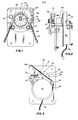
- FIGURE 1 is a front elevational view of a peristaltic pump, incorporating the pressure surface of this invention.
- FIGURE 2 is a side elevational view partially in section of the peristaltic pump of FIGURE 1.
- FIGURE 3 is a rear elevational view of the peristaltic pump of FIGURE 1.
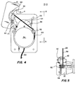
- FIGURE 4 is a view similar to FIGURE 3; however, the pressure surface has been moved away from the pump rotor.
- FIGURE 5 is a partial side elevational view taken at line 5-5 of FIGURE 4.
- Utilization of the device of the present invention may be.best understood by reference to peristaltic pump, generally 20 as shown in FIGURE 1.
Pump 20 consists of four main parts; specificallytubing guide piece 12,flexible tubing 22,rotatable pump head 24 andpressure plate 10. Aspump head 24 rotates,pressure wheels 26 contactflexible tubing 22 to repetitively and successively compressflexible tubing 22. Arcuate surface 11 ofpressure plate 10 operatively engagesflexible tubing 22 to provide a surface against whichpressure wheels 26 may compressflexible tubing 22. If desired arcuate surface may be bordered by a fence 13 which acts to retainflexible tubing 22 in operative engagement with apump head 24. - FIGURE 2 illustrates the mounting of
pressure plate 10 with respect topump head 24. Arotatable pivot bar 14 extends throughpressure plate 10.Pressure plate 10 is held in place onrotatable pivot bar 14 by setscrew 36. As shown in FIGURES 3 and 5arm 44 is attached to the opposite end ofpivot bar 14 isarm 44. Anelectrical switch 30 may be placed onarm 44 to indicate the position ofarm 44. -
Pressure plate 10 is held in position byspring 28.Spring 28 consists of aspring retainer 64, acoil portion 62, astraight portion 58 and a bent-overportion 56. The action ofstraight portion 58 againstcam finger 42 causesarm 44 to be biased in a downward manner. This downward biasing ofarm 44 causespump pressure plate 10 to remain in contact with and provide a surface for the compression offlexible tubing 22. - .When it is desired to operatively engage
flexible tubing 22 withpump head 24 to operateperistaltic pump 20pressure plate 10 is moved out of the way as shown in FIGURE 4. As shown in FIGURE 1flexible tubing 22 may now be threaded throughtubing guide 12 and overpressure wheels 26. Whenflexible tubing 22 is properly inplace pressure plate 10 may be moved back into position over flexible tubing 22-by manually graspingknob 16 and moving it into contact withflexible tubing 22. If desired an automatic spring return may be used. As can be best seen by comparing FIGURES 3 and 4 the moving ofpressure plate 10 causescam finger 42 to slide downstraight portion 58 ofspring 28.Electrical switch 30 will signal the position of thepressure head 10. - When electrical power is applied through
lead 50 to motor 32 a rotating motion is imparted throughspeed reducer 34 to driveaxle 18. Driveaxle 18 causesrotatable pump head 24 to rotate. Asrotatable pump head 24 rotates the incompressibility of fluid and the size and durometer offlexible tubing 22 will causepressure plate 10 to move or float with respect topivot bar 14 as the pump operates.Spring 28 provides a biasing force forpressure plate 10 againstflexible tubing 22. - When the requisite amount of fluid has been pumped to the patient the rotation of
rotatable pump head 24 may be stopped andflexible tubing 22 may be removed from theperistaltic pump 20. This removal offlexible tubing 22 is accomplished by graspingknob 16 and movingpressure plate 10 up and away fromflexible tubing 22 to the position shown in FIGURE 4. Aspressure plate 10 is moved away fromrotatable pump head 24cam finger 42 slides up along the straight portion ofspring 28. Whencam finger 42 reaches bent-overportion 56 ofspring 28 the downward force felt at bent-overportion 56 caused by the action ofcoil portion 62, held in place byspring retainer 64, will allowpressure plate 10 to remain in the open position. If the automatic return is usedplate 10 will return to the closed position when released. Closing ofpressure plate 10 again is easily effected by graspingknob 16 and movingpressure plate 10 back into contact withflexible tubing 22. - In this
manner pressure surface 10 around rotatableperistaltic pump head 24 is allowed to rotate on thepivot bar 14 in response to any eccentricities in the rotating pump head or irregularities in the flexible tubing. - The foregoing invention can now be practiced by those skilled in the art. Such skilled persons will know that the invention is not necessarily restricted to the embodiments presented herein. The scope of the invention is to be defined by the terms of the following claims, as given meaning by the preceding description.
Claims (10)
whereby when said plate member is rotated on said pivot member into a position for operative engagement with the flexible tubing, said means for resiliently biasing said arcuate surface against the flexible tubing will hold said arcuate surface in operative engagement with the flexible tubing.
Applications Claiming Priority (2)
| Application Number | Priority Date | Filing Date | Title |
|---|---|---|---|
| US63859784A | 1984-08-07 | 1984-08-07 | |
| US638597 | 1984-08-07 |
Publications (3)
| Publication Number | Publication Date |
|---|---|
| EP0173075A2 true EP0173075A2 (en) | 1986-03-05 |
| EP0173075A3 EP0173075A3 (en) | 1986-03-19 |
| EP0173075B1 EP0173075B1 (en) | 1990-10-10 |
Family
ID=24560677
Family Applications (1)
| Application Number | Title | Priority Date | Filing Date |
|---|---|---|---|
| EP85109278A Expired - Lifetime EP0173075B1 (en) | 1984-08-07 | 1985-07-25 | Peristaltic pump |
Country Status (6)
| Country | Link |
|---|---|
| EP (1) | EP0173075B1 (en) |
| JP (1) | JPH06103029B2 (en) |
| KR (1) | KR940007757B1 (en) |
| AU (1) | AU592760B2 (en) |
| CA (1) | CA1258403A (en) |
| DE (1) | DE3580074D1 (en) |
Cited By (7)
| Publication number | Priority date | Publication date | Assignee | Title |
|---|---|---|---|---|
| US5057081A (en) * | 1990-06-15 | 1991-10-15 | Sherwood Medical Company | Peristaltic infusion device |
| US5127908A (en) * | 1990-06-15 | 1992-07-07 | Sherwood Medical Company | Peristaltic infusion device |
| US5133650A (en) * | 1990-06-15 | 1992-07-28 | Sherwood Medical Company | Infusion device rotor shield |
| US5147312A (en) * | 1990-06-15 | 1992-09-15 | Sherwood Medical Company | Peristaltic infusion device drip chamber yoke |
| US5158528A (en) * | 1990-06-15 | 1992-10-27 | Sherwood Medical Company | Peristaltic infusion device and charger unit |
| US5181842A (en) * | 1990-06-15 | 1993-01-26 | Sherwood Medical Company | Peristaltic infusion device |
| US10519123B2 (en) * | 2016-02-04 | 2019-12-31 | Grasim Industries Limited | Process for preparation of an aromatic N-glycidylamine |
Families Citing this family (2)
| Publication number | Priority date | Publication date | Assignee | Title |
|---|---|---|---|---|
| KR100299269B1 (en) * | 1999-08-30 | 2001-09-22 | 황해웅 | A manufacturing device &method for mixing fiber by using brading weaving |
| KR101454468B1 (en) * | 2013-11-21 | 2014-10-24 | 서해영 | Discharge improved disinfectant nebulizer using peristaltic pump |
Citations (3)
| Publication number | Priority date | Publication date | Assignee | Title |
|---|---|---|---|---|
| FR1562024A (en) * | 1968-01-05 | 1969-04-04 | ||
| GB1344825A (en) * | 1971-05-19 | 1974-01-23 | Vendaid Ltd | Machines for dispensing measured quantities of liquids |
| US4165954A (en) * | 1975-08-11 | 1979-08-28 | Corning Glass Works | Linear peristaltic pump having pivotal pump arm |
Family Cites Families (3)
| Publication number | Priority date | Publication date | Assignee | Title |
|---|---|---|---|---|
| JPS5565538U (en) * | 1978-10-31 | 1980-05-06 | ||
| DE2855634A1 (en) * | 1978-12-22 | 1980-06-26 | Ara Werk Kraemer Gmbh & Co | METHOD AND DEVICE FOR PUMPING, IN PARTICULAR DOSING, FROM PASTOISES TO LIQUID MEASURES BY MEANS OF A HOSE PUMP |
| US4493224A (en) * | 1982-06-04 | 1985-01-15 | Eaton Corporation | Remote manual shifting mechanism |
-
1985
- 1985-07-25 AU AU45368/85A patent/AU592760B2/en not_active Ceased
- 1985-07-25 DE DE8585109278T patent/DE3580074D1/en not_active Expired - Lifetime
- 1985-07-25 EP EP85109278A patent/EP0173075B1/en not_active Expired - Lifetime
- 1985-08-06 CA CA000488102A patent/CA1258403A/en not_active Expired
- 1985-08-06 JP JP60171945A patent/JPH06103029B2/en not_active Expired - Lifetime
- 1985-08-06 KR KR1019850005651A patent/KR940007757B1/en not_active IP Right Cessation
Patent Citations (3)
| Publication number | Priority date | Publication date | Assignee | Title |
|---|---|---|---|---|
| FR1562024A (en) * | 1968-01-05 | 1969-04-04 | ||
| GB1344825A (en) * | 1971-05-19 | 1974-01-23 | Vendaid Ltd | Machines for dispensing measured quantities of liquids |
| US4165954A (en) * | 1975-08-11 | 1979-08-28 | Corning Glass Works | Linear peristaltic pump having pivotal pump arm |
Cited By (7)
| Publication number | Priority date | Publication date | Assignee | Title |
|---|---|---|---|---|
| US5057081A (en) * | 1990-06-15 | 1991-10-15 | Sherwood Medical Company | Peristaltic infusion device |
| US5127908A (en) * | 1990-06-15 | 1992-07-07 | Sherwood Medical Company | Peristaltic infusion device |
| US5133650A (en) * | 1990-06-15 | 1992-07-28 | Sherwood Medical Company | Infusion device rotor shield |
| US5147312A (en) * | 1990-06-15 | 1992-09-15 | Sherwood Medical Company | Peristaltic infusion device drip chamber yoke |
| US5158528A (en) * | 1990-06-15 | 1992-10-27 | Sherwood Medical Company | Peristaltic infusion device and charger unit |
| US5181842A (en) * | 1990-06-15 | 1993-01-26 | Sherwood Medical Company | Peristaltic infusion device |
| US10519123B2 (en) * | 2016-02-04 | 2019-12-31 | Grasim Industries Limited | Process for preparation of an aromatic N-glycidylamine |
Also Published As
| Publication number | Publication date |
|---|---|
| AU592760B2 (en) | 1990-01-25 |
| KR860001954A (en) | 1986-03-24 |
| CA1258403A (en) | 1989-08-15 |
| KR940007757B1 (en) | 1994-08-24 |
| EP0173075B1 (en) | 1990-10-10 |
| JPS6143290A (en) | 1986-03-01 |
| JPH06103029B2 (en) | 1994-12-14 |
| EP0173075A3 (en) | 1986-03-19 |
| AU4536885A (en) | 1986-02-13 |
| DE3580074D1 (en) | 1990-11-15 |
Similar Documents
| Publication | Publication Date | Title |
|---|---|---|
| US4708604A (en) | Pressure surface for a peristaltic pump | |
| EP0173075A2 (en) | Peristaltic pump | |
| US4893991A (en) | Method and means for improving efficiency of peristaltic pumps | |
| US3778195A (en) | Pump for parenteral injections and the like | |
| JP2885416B2 (en) | Peristaltic pump with cartridge | |
| US2877714A (en) | Variable displacement tubing pump | |
| CA2199156A1 (en) | Fluid Delivery System with Mounting Linkage | |
| GB2138511A (en) | Peristaltic pump and pumphead therefor | |
| EP0606099B1 (en) | Peristaltic pump | |
| US2915421A (en) | Doctor blade and control means therefor | |
| US4553323A (en) | Component placement head control | |
| US5237898A (en) | Autotaper | |
| US4653673A (en) | Pump for precisely dispensing liquids | |
| US5329664A (en) | Cleaning device for a threaded shaft | |
| CN213117339U (en) | Screw thread stop device | |
| CN217152255U (en) | Injection pump | |
| CN112128332B (en) | Screw thread stop device | |
| CN117226896B (en) | Surface cutting layering device of belt for transmission equipment | |
| US3948133A (en) | Rotary blade cutting assembly | |
| CN220037368U (en) | Compressor installing support | |
| SU1583746A1 (en) | Peristaltic metering device for of viscous liquids | |
| EP0217795A1 (en) | A device for guiding a tool along a curve. | |
| EP1694384A1 (en) | An improved feed mechanism for a medical device | |
| ES281911U (en) | Peristaltic pump of roller type (Machine-translation by Google Translate, not legally binding) | |
| KR830001096Y1 (en) | Rapier Drive of Automatic Loom |
Legal Events
| Date | Code | Title | Description |
|---|---|---|---|
| PUAI | Public reference made under article 153(3) epc to a published international application that has entered the european phase |
Free format text: ORIGINAL CODE: 0009012 |
|
| PUAL | Search report despatched |
Free format text: ORIGINAL CODE: 0009013 |
|
| AK | Designated contracting states |
Kind code of ref document: A2 Designated state(s): BE CH DE FR GB IT LI NL SE |
|
| AK | Designated contracting states |
Kind code of ref document: A3 Designated state(s): BE CH DE FR GB IT LI NL SE |
|
| 17P | Request for examination filed |
Effective date: 19860603 |
|
| 17Q | First examination report despatched |
Effective date: 19871005 |
|
| GRAA | (expected) grant |
Free format text: ORIGINAL CODE: 0009210 |
|
| AK | Designated contracting states |
Kind code of ref document: B1 Designated state(s): BE CH DE FR GB IT LI NL SE |
|
| ET | Fr: translation filed | ||
| REF | Corresponds to: |
Ref document number: 3580074 Country of ref document: DE Date of ref document: 19901115 |
|
| ITF | It: translation for a ep patent filed |
Owner name: MODIANO & ASSOCIATI S.R.L. |
|
| PGFP | Annual fee paid to national office [announced via postgrant information from national office to epo] |
Ref country code: SE Payment date: 19910628 Year of fee payment: 7 |
|
| PGFP | Annual fee paid to national office [announced via postgrant information from national office to epo] |
Ref country code: FR Payment date: 19910721 Year of fee payment: 7 |
|
| PGFP | Annual fee paid to national office [announced via postgrant information from national office to epo] |
Ref country code: NL Payment date: 19910731 Year of fee payment: 7 |
|
| PLBE | No opposition filed within time limit |
Free format text: ORIGINAL CODE: 0009261 |
|
| STAA | Information on the status of an ep patent application or granted ep patent |
Free format text: STATUS: NO OPPOSITION FILED WITHIN TIME LIMIT |
|
| 26N | No opposition filed | ||
| PGFP | Annual fee paid to national office [announced via postgrant information from national office to epo] |
Ref country code: CH Payment date: 19911003 Year of fee payment: 7 |
|
| PGFP | Annual fee paid to national office [announced via postgrant information from national office to epo] |
Ref country code: BE Payment date: 19911106 Year of fee payment: 7 |
|
| PG25 | Lapsed in a contracting state [announced via postgrant information from national office to epo] |
Ref country code: SE Effective date: 19920726 |
|
| PG25 | Lapsed in a contracting state [announced via postgrant information from national office to epo] |
Ref country code: LI Effective date: 19920731 Ref country code: CH Effective date: 19920731 Ref country code: BE Effective date: 19920731 |
|
| BERE | Be: lapsed |
Owner name: ABBOTT LABORATORIES Effective date: 19920731 |
|
| PG25 | Lapsed in a contracting state [announced via postgrant information from national office to epo] |
Ref country code: NL Effective date: 19930201 |
|
| NLV4 | Nl: lapsed or anulled due to non-payment of the annual fee | ||
| PG25 | Lapsed in a contracting state [announced via postgrant information from national office to epo] |
Ref country code: FR Effective date: 19930331 |
|
| REG | Reference to a national code |
Ref country code: CH Ref legal event code: PL |
|
| REG | Reference to a national code |
Ref country code: FR Ref legal event code: ST |
|
| ITTA | It: last paid annual fee | ||
| EUG | Se: european patent has lapsed |
Ref document number: 85109278.3 Effective date: 19930204 |
|
| REG | Reference to a national code |
Ref country code: GB Ref legal event code: IF02 |
|
| PGFP | Annual fee paid to national office [announced via postgrant information from national office to epo] |
Ref country code: GB Payment date: 20040615 Year of fee payment: 20 |
|
| PGFP | Annual fee paid to national office [announced via postgrant information from national office to epo] |
Ref country code: DE Payment date: 20040730 Year of fee payment: 20 |
|
| PG25 | Lapsed in a contracting state [announced via postgrant information from national office to epo] |
Ref country code: GB Free format text: LAPSE BECAUSE OF EXPIRATION OF PROTECTION Effective date: 20050724 |
|
| REG | Reference to a national code |
Ref country code: GB Ref legal event code: PE20 |