EP0172974A1 - A pneumatic tire - Google Patents
A pneumatic tire Download PDFInfo
- Publication number
- EP0172974A1 EP0172974A1 EP84630123A EP84630123A EP0172974A1 EP 0172974 A1 EP0172974 A1 EP 0172974A1 EP 84630123 A EP84630123 A EP 84630123A EP 84630123 A EP84630123 A EP 84630123A EP 0172974 A1 EP0172974 A1 EP 0172974A1
- Authority
- EP
- European Patent Office
- Prior art keywords
- tire
- circumferential
- mid
- grooves
- lateral
- Prior art date
- Legal status (The legal status is an assumption and is not a legal conclusion. Google has not performed a legal analysis and makes no representation as to the accuracy of the status listed.)
- Granted
Links
- 230000001133 acceleration Effects 0.000 description 1
- 239000011324 bead Substances 0.000 description 1
- 238000010276 construction Methods 0.000 description 1
- 230000000694 effects Effects 0.000 description 1
- 238000012986 modification Methods 0.000 description 1
- 230000004048 modification Effects 0.000 description 1
- XLYOFNOQVPJJNP-UHFFFAOYSA-N water Substances O XLYOFNOQVPJJNP-UHFFFAOYSA-N 0.000 description 1
Images


Classifications
-
- B—PERFORMING OPERATIONS; TRANSPORTING
- B60—VEHICLES IN GENERAL
- B60C—VEHICLE TYRES; TYRE INFLATION; TYRE CHANGING; CONNECTING VALVES TO INFLATABLE ELASTIC BODIES IN GENERAL; DEVICES OR ARRANGEMENTS RELATED TO TYRES
- B60C11/00—Tyre tread bands; Tread patterns; Anti-skid inserts
- B60C11/03—Tread patterns
- B60C11/0302—Tread patterns directional pattern, i.e. with main rolling direction
-
- B—PERFORMING OPERATIONS; TRANSPORTING
- B60—VEHICLES IN GENERAL
- B60C—VEHICLE TYRES; TYRE INFLATION; TYRE CHANGING; CONNECTING VALVES TO INFLATABLE ELASTIC BODIES IN GENERAL; DEVICES OR ARRANGEMENTS RELATED TO TYRES
- B60C11/00—Tyre tread bands; Tread patterns; Anti-skid inserts
- B60C11/03—Tread patterns
- B60C2011/0337—Tread patterns characterised by particular design features of the pattern
- B60C2011/0339—Grooves
- B60C2011/0374—Slant grooves, i.e. having an angle of about 5 to 35 degrees to the equatorial plane
-
- B—PERFORMING OPERATIONS; TRANSPORTING
- B60—VEHICLES IN GENERAL
- B60C—VEHICLE TYRES; TYRE INFLATION; TYRE CHANGING; CONNECTING VALVES TO INFLATABLE ELASTIC BODIES IN GENERAL; DEVICES OR ARRANGEMENTS RELATED TO TYRES
- B60C11/00—Tyre tread bands; Tread patterns; Anti-skid inserts
- B60C11/03—Tread patterns
- B60C2011/0337—Tread patterns characterised by particular design features of the pattern
- B60C2011/0386—Continuous ribs
- B60C2011/0388—Continuous ribs provided at the equatorial plane
Definitions
- This invention relates to pneumatic tires for passenger cars and more particularly to tires for use on high performance vehicles.
- a directional tire is a tire having a tread pattern such that when the tire is rotated in one direction it has different tractional properties with the ground than when it is rotated in the other direction.
- a typical directional tread pattern has lateral grooves that are arranged to form a series of 'V' shaped grooves all pointed in the same direction around the tire tread.
- the 'V' shaped grooves are pointed in the direction of travel, so that the mid portion of each 'V' shaped groove will enter the footprint of the tire first.
- the differences in the tractional properties between the two directions of rotation can be varied by a number of different design parameters, for example the angle of the 'V' shaped grooves make relative to the mid-circumferential plane of the tire, the circumferential spacing between the 'V' shaped grooves, and the land-to-sea ratio of the tread.
- the present invention provides a directional tire in which the tractional properties between the two directions of rotation can be varied by an alternative parameter.
- a pneumatic tire having ground contacting tread portion with a pair of lateral edges and a mid-circumferential portion, the tread portion having a directional tread pattern therein including lateral grooves extending from the mid-circumferential portion towards both lateral edges, all of the lateral grooves extending in the same circumferential direction and forming circumferentially spaced lands therebetween, each of said lands extending continuously from the mid-circumferential portion to a respective lateral edge and having a first face directed in one rotational direction, said first face being continuous from the mid-circumferential portion to the respective lateral edge, and said second face being broken by axially spaced circumferentially extending grooves.
- the circumferentially extending grooves are in the trailing face of the land when the tire is rotated in a direction for forward movement of the vehicle.
- the lateral grooves on each side of the mid-circumferential plane prefferably be of a curved configuration, and to make an overall angle of about 55°-70° with respect to the mid-circumferential plane of the tire.
- the tire 10 is of radial carcass construction and has a ground contacting tread portion 11 with a pair of lateral edges 12 and 13 spaced apart by a tread width TW.
- the tread width TW is defined as the greatest axial distance across the tire as measured from the footprint of the tire when the tire is mounted on a specified rim and is inflated to a design pressure at a rated load and the terms 'axial and axially' refer to distances along or parallel with the axis of rotation of the tire.
- the tread portion 11 is joined at its lateral edges 12 and 13 to a pair of shoulder portions 21 which extend into the sidewalls 14.
- Each sidewall 14 extends radially inwardly from a respective shoulder portion 21 and each terminates in a bead portion 20.
- the tire 10 has a mid-circumferential plane M-M perpendicular to the axis of rotation of the tire and located midway between the lateral edges.
- the tread portion 11 has a directional tread pattern therein including lateral grooves 15 and 16 on each side of the mid-circumferential plane M-M.
- the lateral grooves 15 and 16 extend from a mid-circumferential portion 17, symmetrically located on each side of the plane M-M, towards a respective lateral edge 12 or 13.
- mid portion of the tread is meant upto 15 % of the tread width TW on each side of the plane M-M.
- Each lateral groove 15 or 16 has its axially innermost end 18 or 19 respectively located at approximately 4 % to 5% of the tread width TW from the plane M-M, and each lateral groove 15 or 16 extends axially outwardly and circumferentially in a curve to the respective tread edge 12 or 13 and into the adjacent shoulder 21.
- the lateral grooves 15 on one side of the plane M-M extend circumferentially in the same direction of rotation as the lateral grooves 16 on the other side of the plane so that in appearance the two sets of lateral grooves 15 and 16 form a series of approximately 'V' shaped configurations that are circumferentially spaced around the tread.
- each lateral groove 15 or 16 makes an overall angle ⁇ with respect to the mid-circumferential plane M-M of the tire of between 55° and 70°.
- the overall anglep( is measured between the plane M-M and a straight line L drawn between a first point P 1 at the intersection of the lateral edge of the tread and the center-line C of the respective groove, and a second point P 2 at the intersection of said center-line C and the respective axially inner end 18 or 19 of the groove.
- the lateral grooves 15 to one side of the plane M-M are circumferentially off-set from the grooves 16 on the other side of the plane M-M by a circumferential distance on one half (1/2) the pitch between adjacent lateral grooves.
- the lateral grooves 15 and 16 on each side of the plane M-M form circumferentially spaced lands, 25 and 26 respectively, therebetween.
- Each land 25 and 26 extends continuously from the mid-circumferential portion 17 of the tread to a respective lateral edge.
- the lands 25 and 26, each have a first face 27 directed in one direction of rotation of the tire and a second face 28 directed in the other direction of rotation of the tire. Because the tire is directional it is expected that when the tire is mounted on a vehicle, for forward movement the tire rotates so that the apex of the 'V' configuration enters the footprint of the tire first. Hence in this particular use of the tire, the first faces 27 are the leading faces of the lands 25 and 26 and the second faces 28 are the trailing faces of the lands.
- the leading faces 27 are continuous curved surfaces extending from the mid-portion 17 to the respective tread edge 12 or 13.
- the trailing faces 28 are also arcuate surfaces but are non-continuous in that each surface 28 is interrupted by three circumferentially extending grooves 31, 32, and 33 which extend from the trailing face 28 of each land towards the leading face 27.
- the circumferentially extending grooves 31, 32, and 33 increase in their respective axial widths W 1 , W 2 and W 3 in stepwise progression axially outwardly from the mid-circumferential plane M-M, and each circumferential groove extends across its respective land 26 for between 70 % to 80 % of the circumferential length of the land.
- the axial width W 1 , W 2 , and W 3 are related in that W 3 is approximately equal to 2.2 W1, and W 2 is approximately equal to 1.4 W 1 .
- the circumferentially extending grooves 31, 32, and 33 in each land 25 or 26 are axially aligned on each side of the plane M-M, so that the grooves 31, 32, and 33 lie on respective straight axially spaced circular path around the tread on each side of the plane M-M.
- the axially inner circumferential grooves 31 are all located at a distance D 1 from the plane M-M, the distance D 1 being approximately 4 % of the tread width TW.
- the distance D 2 between the circumferentially extending grooves 31 and the adjacent axially outer circumferentially extending grooves 32 is approximately equal to 1.7 D 1
- the distance D 3 between the circumferential grooves 32 and the adjacent axially outer grooves 33 is approximately equal to 2.5 D 1
- the distance D 4 between the circumferentially extending grooves 33 and the respective lateral edge of the tread is approximately 4.5 D 1 .
- the lands 25 and 26 have a continuous leading face 27 and a broken, or discontinuous, trailing face 28 the traction grip of the tire on a driving surface is further modified in the forward direction relative to the reverse direction. This is because the continuous leading face 27 provides a continuous edge for contact with the ground as compared with the more flexible broken trailing face 28.
- Fig. 4 there is illustrated a fragmentary plan view of the tread portion of a tire.
- the tread portion illustrated differs from that shown in Figs. 1-3 in that the lateral grooves 115 and 116 are not circumferentially staggered as previously described but are aligned one with the other to give a more true 'V' shape configuration.
- the blades 137 extending from the mouth of the axially inner circumferential grooves 131 join each other, thereby linking each lateral groove 115 on one side of the plane M-M with it aligned neighbouring groove 116 on the other side of the plane.
- the tread portion of Fig. 4 is the same as the tread illustrated in Figs. 1-3.
- the present invention is applicable to directional tires which are to be mounted on a vehicle so that the side portions of the 'V' shaped grooves enter the footprint first during forward movement of the vehicle.
Landscapes
- Engineering & Computer Science (AREA)
- Mechanical Engineering (AREA)
- Tires In General (AREA)
Abstract
Description
- This invention relates to pneumatic tires for passenger cars and more particularly to tires for use on high performance vehicles.
- A modern trend is for the tread pattern, formed by grooves and lands in the ground contacting tread portion of a tire, to be directional. A directional tire is a tire having a tread pattern such that when the tire is rotated in one direction it has different tractional properties with the ground than when it is rotated in the other direction. A typical directional tread pattern has lateral grooves that are arranged to form a series of 'V' shaped grooves all pointed in the same direction around the tire tread. Usually for maximum traction grip during acceleration of high performance cars the 'V' shaped grooves are pointed in the direction of travel, so that the mid portion of each 'V' shaped groove will enter the footprint of the tire first.
- Typical examples of this type of tire are illustrated in European Patent Application 0 064 934 A, British Patent Application GB 2 046 188 A, and U.S. Patent 4 057 089.
- The differences in the tractional properties between the two directions of rotation can be varied by a number of different design parameters, for example the angle of the 'V' shaped grooves make relative to the mid-circumferential plane of the tire, the circumferential spacing between the 'V' shaped grooves, and the land-to-sea ratio of the tread.
- The present invention provides a directional tire in which the tractional properties between the two directions of rotation can be varied by an alternative parameter.
- According to the invention there is provided a pneumatic tire having ground contacting tread portion with a pair of lateral edges and a mid-circumferential portion, the tread portion having a directional tread pattern therein including lateral grooves extending from the mid-circumferential portion towards both lateral edges, all of the lateral grooves extending in the same circumferential direction and forming circumferentially spaced lands therebetween, each of said lands extending continuously from the mid-circumferential portion to a respective lateral edge and having a first face directed in one rotational direction, said first face being continuous from the mid-circumferential portion to the respective lateral edge, and said second face being broken by axially spaced circumferentially extending grooves.
- Preferably the circumferentially extending grooves are in the trailing face of the land when the tire is rotated in a direction for forward movement of the vehicle.
- It is preferable for the lateral grooves on each side of the mid-circumferential plane to be of a curved configuration, and to make an overall angle of about 55°-70° with respect to the mid-circumferential plane of the tire.
- The invention will be described by way of example of and with reference to the accompanying drawings in which:
- - Fig. 1 is a perspective view of a tire according to the invention;
- - Fig. 2 is a front elevation of the tire illustrated in Fig. 1;
- - Fig. 3 is a fragmentary enlarged plan view of the tread portion of the tire illustrated in Figs. 1 and 2;
- - Fig. 4 is a fragmentary enlarged plan view of the tread portion of a second tire also according to this invention, and
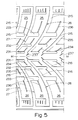
- - Fig. 5 is a fragmentary enlarged plan view of the tread portion of yet another tire also according to this invention.
- With reference to Fig. 1, Fig. 2 and Fig. 3, there is illustrated a
pneumatic tire 10 for a passenger car and in particular for a car that is to be driven at high speed on either roads or racing circuits. Thetire 10 is of radial carcass construction and has a ground contactingtread portion 11 with a pair oflateral edges tread portion 11 is joined at itslateral edges shoulder portions 21 which extend into thesidewalls 14. Eachsidewall 14 extends radially inwardly from arespective shoulder portion 21 and each terminates in abead portion 20. - The
tire 10 has a mid-circumferential plane M-M perpendicular to the axis of rotation of the tire and located midway between the lateral edges. Thetread portion 11 has a directional tread pattern therein includinglateral grooves lateral grooves mid-circumferential portion 17, symmetrically located on each side of the plane M-M, towards a respectivelateral edge lateral groove innermost end lateral groove respective tread edge adjacent shoulder 21. Thelateral grooves 15 on one side of the plane M-M extend circumferentially in the same direction of rotation as thelateral grooves 16 on the other side of the plane so that in appearance the two sets oflateral grooves lateral groove inner end lateral grooves 15 to one side of the plane M-M are circumferentially off-set from thegrooves 16 on the other side of the plane M-M by a circumferential distance on one half (1/2) the pitch between adjacent lateral grooves. - The
lateral grooves land mid-circumferential portion 17 of the tread to a respective lateral edge. Thelands first face 27 directed in one direction of rotation of the tire and asecond face 28 directed in the other direction of rotation of the tire. Because the tire is directional it is expected that when the tire is mounted on a vehicle, for forward movement the tire rotates so that the apex of the 'V' configuration enters the footprint of the tire first. Hence in this particular use of the tire, thefirst faces 27 are the leading faces of thelands second faces 28 are the trailing faces of the lands. - The leading
faces 27 are continuous curved surfaces extending from themid-portion 17 to therespective tread edge trailing faces 28 are also arcuate surfaces but are non-continuous in that eachsurface 28 is interrupted by three circumferentially extendinggrooves trailing face 28 of each land towards the leadingface 27. The circumferentially extendinggrooves respective land 26 for between 70 % to 80 % of the circumferential length of the land. The axial width W1, W2, and W3 are related in that W3 is approximately equal to 2.2 W1, and W2 is approximately equal to 1.4 W1. - The circumferentially extending
grooves land grooves circumferential grooves 31 are all located at a distance D1 from the plane M-M, the distance D1 being approximately 4 % of the tread width TW. The distance D2 between the circumferentially extendinggrooves 31 and the adjacent axially outer circumferentially extendinggrooves 32 is approximately equal to 1.7 D1, the distance D3 between thecircumferential grooves 32 and the adjacent axiallyouter grooves 33 is approximately equal to 2.5 D1, and the distance D4 between the circumferentially extendinggrooves 33 and the respective lateral edge of the tread is approximately 4.5 D1. Thus it can be seen that as the distances D1, D2' D31 and D4 increase in stepwise progression axially outwardly from the center plane M-M, so do the axial widths W1, W2, and W3 of thecircumferential grooves - The circumferentially extending
grooves blade 34,-35 and 36 respectively, extending axially outwardly from the groove for a distance which is at least twice the width of the respective groove from which it extends. For the purposes of this invention a blade (sometimes called a sipe) is a narrow groove which closes in the footprint of the tire. Eachblade respective groove circumferential groove 31 also has anadditional blade 37 which extends axially inwards from the mouth of thegroove 31 to the plane M-M. - Because the
lands face 27 and a broken, or discontinuous, trailingface 28 the traction grip of the tire on a driving surface is further modified in the forward direction relative to the reverse direction. This is because the continuous leadingface 27 provides a continuous edge for contact with the ground as compared with the more flexible brokentrailing face 28. - During braking the
trailing faces 28 are loaded and distort in a circumferential direction until theblades faces 27 of each land helps to support thetrailing face 28. This also has a further advantage of allowing thelateral grooves - In Fig. 4 there is illustrated a fragmentary plan view of the tread portion of a tire. The tread portion illustrated differs from that shown in Figs. 1-3 in that the
lateral grooves lateral grooves blades 137 extending from the mouth of the axially inner circumferential grooves 131 join each other, thereby linking eachlateral groove 115 on one side of the plane M-M with it aligned neighbouringgroove 116 on the other side of the plane. In all other essential matters the tread portion of Fig. 4 is the same as the tread illustrated in Figs. 1-3. - Fig. 5 illustrated yet another embodiment of the invention. The tread portion is similar to that illustrated in Fig. 4. The
lateral grooves faces 27 of thelands trailing faces 28 are continuous. This is the opposite of the tire illustrated in Figs. 3 and 4. - The leading faces 27 of the lands are interrupted by circumferentially extending
groove grooves grooves face 27 towards the trailingface 28. - The
blades lateral grooves blades blades 237 in themid-circumferential portion 17 are formed along the directional path of thelateral grooves - Because the leading faces 27 of the
lands circumferentially extending grooves face 28 is continuous, then the traction grip of the tire on a driving surface is modified relative to the traction grip in the reverse direction of rotation so as to provide a different effect from the embodiment shown in Figure 1. - It is also envisage that the present invention is applicable to directional tires which are to be mounted on a vehicle so that the side portions of the 'V' shaped grooves enter the footprint first during forward movement of the vehicle.
- While certain representative embodiments and details have been shown for the purpose of illustrating the invention it will be apparent to those skilled in the art that various modifications could be made without departing from the scope of the invention. For example, the
blades
Claims (11)
Priority Applications (9)
| Application Number | Priority Date | Filing Date | Title |
|---|---|---|---|
| EP84630123A EP0172974B1 (en) | 1984-08-28 | 1984-08-28 | A pneumatic tire |
| DE8484630123T DE3470703D1 (en) | 1984-08-28 | 1984-08-28 | A pneumatic tire |
| US06/745,458 US4667717A (en) | 1984-08-28 | 1985-06-17 | Pneumatic tire |
| AU44607/85A AU546979B3 (en) | 1984-08-28 | 1985-07-04 | A pneumatic tire |
| ZA856169A ZA856169B (en) | 1984-08-28 | 1985-08-14 | A pneumatic tire |
| JP1985127936U JPH0318242Y2 (en) | 1984-08-28 | 1985-08-23 | |
| KR2019850011044U KR890006132Y1 (en) | 1984-08-28 | 1985-08-28 | Pneumatic tire |
| FR8512852A FR2569622B3 (en) | 1984-08-28 | 1985-08-28 | PNEUMATIC TAPE FOR PASSENGER VEHICLE |
| DE8524632U DE8524632U1 (en) | 1984-08-28 | 1985-08-28 | tire |
Applications Claiming Priority (1)
| Application Number | Priority Date | Filing Date | Title |
|---|---|---|---|
| EP84630123A EP0172974B1 (en) | 1984-08-28 | 1984-08-28 | A pneumatic tire |
Publications (2)
| Publication Number | Publication Date |
|---|---|
| EP0172974A1 true EP0172974A1 (en) | 1986-03-05 |
| EP0172974B1 EP0172974B1 (en) | 1988-04-27 |
Family
ID=8192968
Family Applications (1)
| Application Number | Title | Priority Date | Filing Date |
|---|---|---|---|
| EP84630123A Expired EP0172974B1 (en) | 1984-08-28 | 1984-08-28 | A pneumatic tire |
Country Status (8)
| Country | Link |
|---|---|
| US (1) | US4667717A (en) |
| EP (1) | EP0172974B1 (en) |
| JP (1) | JPH0318242Y2 (en) |
| KR (1) | KR890006132Y1 (en) |
| AU (1) | AU546979B3 (en) |
| DE (2) | DE3470703D1 (en) |
| FR (1) | FR2569622B3 (en) |
| ZA (1) | ZA856169B (en) |
Cited By (11)
| Publication number | Priority date | Publication date | Assignee | Title |
|---|---|---|---|---|
| GB2192842A (en) * | 1986-06-13 | 1988-01-27 | Bridgestone Corp | Pneumatic tire |
| EP0375596A2 (en) * | 1988-12-21 | 1990-06-27 | The Goodyear Tire & Rubber Company | Tread for a pneumatic tire |
| FR2655920A1 (en) * | 1989-12-20 | 1991-06-21 | Uniroyal Englebert Gmbh | PNEUMATIC VEHICLE. |
| GB2240521A (en) * | 1990-01-10 | 1991-08-07 | Uniroyal Englebert Gmbh | Tyre tread pattern |
| EP0503404A1 (en) * | 1991-03-08 | 1992-09-16 | The Goodyear Tire & Rubber Company | Pneumatic tire having improved wet traction |
| EP0503407A1 (en) * | 1991-03-08 | 1992-09-16 | The Goodyear Tire & Rubber Company | Pneumatic tire having laterally connected lugs |
| EP0508090A1 (en) * | 1991-03-08 | 1992-10-14 | The Goodyear Tire & Rubber Company | Pneumatic tire having a unique footprint |
| WO1999017943A1 (en) * | 1997-10-04 | 1999-04-15 | Philip Blood | Tyre |
| GB2343159A (en) * | 1998-10-26 | 2000-05-03 | Sumitomo Rubber Ind | Pneumatic tyre tread portion |
| EP2230101A1 (en) | 2009-03-16 | 2010-09-22 | The Yokohama Rubber Co., Ltd. | Pneumatic tire |
| EP2230100A1 (en) * | 2009-03-16 | 2010-09-22 | The Yokohama Rubber Company, Limited | Pneumatic tire |
Families Citing this family (28)
| Publication number | Priority date | Publication date | Assignee | Title |
|---|---|---|---|---|
| JPH0692201B2 (en) * | 1986-03-14 | 1994-11-16 | 株式会社ブリヂストン | Pneumatic radial tire for high speed |
| US4732194A (en) * | 1986-04-17 | 1988-03-22 | The Yokohama Rubber Co., Ltd. | Asymmetric tire and tread |
| US4862934A (en) * | 1986-08-12 | 1989-09-05 | Bridgestone Corporation | Heavy duty pneumatic tires with composite tread patterns |
| JPS6452507A (en) * | 1987-05-08 | 1989-02-28 | Bridgestone Corp | Pneumatic tire pair |
| AT392035B (en) * | 1988-04-07 | 1991-01-10 | Semperit Ag | RUNNING PROFILE FOR A VEHICLE AIR TIRE |
| JPH01314609A (en) * | 1988-06-15 | 1989-12-19 | Yokohama Rubber Co Ltd:The | Pneumatic tire |
| US5327952A (en) * | 1991-03-08 | 1994-07-12 | The Goodyear Tire & Rubber Company | Pneumatic tire having improved wet traction |
| US5358022A (en) * | 1991-03-08 | 1994-10-25 | The Goodyear Tire & Rubber Company | Pneumatic tire having improved wet traction |
| DE4108745A1 (en) * | 1991-03-18 | 1992-09-24 | Sp Reifenwerke Gmbh | TIRE |
| US5360043A (en) * | 1991-07-26 | 1994-11-01 | The Goodyear Tire & Rubber Company | Asymmetric tread for a tire |
| DE4319713A1 (en) * | 1993-06-15 | 1994-12-22 | David Brannan | Tyre for a vehicle |
| USD384921S (en) * | 1995-12-20 | 1997-10-14 | The Goodyear Tire & Rubber Company | Tire tread |
| USD409536S (en) * | 1997-12-15 | 1999-05-11 | Metzeler Reifen Gmbh | Motorcycle tire |
| EP0997323B1 (en) * | 1998-10-30 | 2006-03-22 | Sumitomo Rubber Industries Ltd. | Vehicle tyre |
| US6378583B1 (en) * | 2000-02-28 | 2002-04-30 | The Goodyear Tire & Rubber Company | Heel and toe wear balancing |
| US6968881B2 (en) * | 2003-06-23 | 2005-11-29 | The Goodyear Tire & Rubber Company | Pneumatic tire including steeply slanted grooves, rib having sipes and blocks having sipes |
| US7143798B2 (en) * | 2003-06-23 | 2006-12-05 | The Goodyear Tire & Rubber Company | Pneumatic tire having tread with axially adjacent block chamfer and rib chamfer |
| US7028733B2 (en) * | 2003-06-23 | 2006-04-18 | The Goodyear Tire & Rubber Company | Pneumatic tire having circumferentially extending rib with chamfers |
| ITTO20040908A1 (en) * | 2004-12-28 | 2005-03-28 | Bridgestone Technical Ct Europ | TIRE FOR AGRICULTURAL USE |
| JP4751161B2 (en) * | 2005-09-20 | 2011-08-17 | 株式会社ブリヂストン | Pneumatic tire |
| US20080149236A1 (en) * | 2006-12-21 | 2008-06-26 | Gia Van Nguyen | Pneumatic tire |
| FR2935296B1 (en) * | 2008-08-26 | 2011-07-29 | Michelin Soc Tech | TIRE TREAD WITH DIRECTIONAL SCULPTURE. |
| US8357254B2 (en) * | 2010-01-29 | 2013-01-22 | Bridgestone Bandag, Llc | Method and apparatus for improved tread splicing |
| JP5391231B2 (en) * | 2011-05-12 | 2014-01-15 | 住友ゴム工業株式会社 | Pneumatic tire |
| JP5432967B2 (en) * | 2011-10-27 | 2014-03-05 | 住友ゴム工業株式会社 | Pneumatic tire |
| JP5344064B2 (en) * | 2012-04-13 | 2013-11-20 | 横浜ゴム株式会社 | Pneumatic tire |
| JP6434270B2 (en) * | 2014-10-07 | 2018-12-05 | 株式会社ブリヂストン | Pneumatic tire for snow |
| RU2703006C2 (en) * | 2015-04-03 | 2019-10-15 | Сумитомо Раббер Индастриз, Лтд. | Pneumatic tire |
Citations (8)
| Publication number | Priority date | Publication date | Assignee | Title |
|---|---|---|---|---|
| US2971552A (en) * | 1958-06-12 | 1961-02-14 | Dayco Corp | Pneumatic tire |
| US2972368A (en) * | 1958-05-26 | 1961-02-21 | Dayco Corp | Vehicle tire |
| US3457981A (en) * | 1965-07-31 | 1969-07-29 | Gen Etablissements Michelin Ra | Pneumatic tires |
| FR2291879A1 (en) * | 1974-11-21 | 1976-06-18 | Continental Gummi Werke Ag | MOTOR VEHICLE TIRES |
| US4166490A (en) * | 1976-11-30 | 1979-09-04 | Uniroyal Gmbh | Pneumatic radial tire |
| US4178199A (en) * | 1976-04-05 | 1979-12-11 | Uniroyal, Inc. | Noise reduction in pneumatic tires |
| GB2046188A (en) * | 1979-04-12 | 1980-11-12 | Dunlop Ltd | Improvements Relating to Tyres |
| EP0064934A2 (en) * | 1981-05-11 | 1982-11-17 | The Goodyear Tire & Rubber Company | High speed tires |
-
1984
- 1984-08-28 EP EP84630123A patent/EP0172974B1/en not_active Expired
- 1984-08-28 DE DE8484630123T patent/DE3470703D1/en not_active Expired
-
1985
- 1985-06-17 US US06/745,458 patent/US4667717A/en not_active Expired - Lifetime
- 1985-07-04 AU AU44607/85A patent/AU546979B3/en not_active Expired
- 1985-08-14 ZA ZA856169A patent/ZA856169B/en unknown
- 1985-08-23 JP JP1985127936U patent/JPH0318242Y2/ja not_active Expired
- 1985-08-28 FR FR8512852A patent/FR2569622B3/en not_active Expired
- 1985-08-28 DE DE8524632U patent/DE8524632U1/en not_active Expired
- 1985-08-28 KR KR2019850011044U patent/KR890006132Y1/en not_active IP Right Cessation
Patent Citations (8)
| Publication number | Priority date | Publication date | Assignee | Title |
|---|---|---|---|---|
| US2972368A (en) * | 1958-05-26 | 1961-02-21 | Dayco Corp | Vehicle tire |
| US2971552A (en) * | 1958-06-12 | 1961-02-14 | Dayco Corp | Pneumatic tire |
| US3457981A (en) * | 1965-07-31 | 1969-07-29 | Gen Etablissements Michelin Ra | Pneumatic tires |
| FR2291879A1 (en) * | 1974-11-21 | 1976-06-18 | Continental Gummi Werke Ag | MOTOR VEHICLE TIRES |
| US4178199A (en) * | 1976-04-05 | 1979-12-11 | Uniroyal, Inc. | Noise reduction in pneumatic tires |
| US4166490A (en) * | 1976-11-30 | 1979-09-04 | Uniroyal Gmbh | Pneumatic radial tire |
| GB2046188A (en) * | 1979-04-12 | 1980-11-12 | Dunlop Ltd | Improvements Relating to Tyres |
| EP0064934A2 (en) * | 1981-05-11 | 1982-11-17 | The Goodyear Tire & Rubber Company | High speed tires |
Cited By (22)
| Publication number | Priority date | Publication date | Assignee | Title |
|---|---|---|---|---|
| GB2192842A (en) * | 1986-06-13 | 1988-01-27 | Bridgestone Corp | Pneumatic tire |
| GB2192842B (en) * | 1986-06-13 | 1991-01-30 | Bridgestone Corp | Pneumatic tire |
| US5152854A (en) * | 1986-06-13 | 1992-10-06 | Bridgestone Corporation | Pneumatic tire having directional tread |
| EP0375596A2 (en) * | 1988-12-21 | 1990-06-27 | The Goodyear Tire & Rubber Company | Tread for a pneumatic tire |
| EP0375596A3 (en) * | 1988-12-21 | 1990-08-29 | The Goodyear Tire & Rubber Company | Tread for a pneumatic tire |
| FR2655920A1 (en) * | 1989-12-20 | 1991-06-21 | Uniroyal Englebert Gmbh | PNEUMATIC VEHICLE. |
| GB2239845A (en) * | 1989-12-20 | 1991-07-17 | Uniroyal Englebert Gmbh | A pneumatic vehicle tyre tread pattern |
| GB2239845B (en) * | 1989-12-20 | 1993-04-14 | Uniroyal Englebert Gmbh | A pneumatic vehicle tyre |
| GB2240521A (en) * | 1990-01-10 | 1991-08-07 | Uniroyal Englebert Gmbh | Tyre tread pattern |
| GB2240521B (en) * | 1990-01-10 | 1994-01-05 | Uniroyal Englebert Gmbh | Tyre tread pattern |
| EP0508090A1 (en) * | 1991-03-08 | 1992-10-14 | The Goodyear Tire & Rubber Company | Pneumatic tire having a unique footprint |
| EP0503407A1 (en) * | 1991-03-08 | 1992-09-16 | The Goodyear Tire & Rubber Company | Pneumatic tire having laterally connected lugs |
| TR25945A (en) * | 1991-03-08 | 1993-11-01 | Goodyear Tire & Rubber | PNEUMATIC TIRE WITH IMPROVED WET DRAWER |
| EP0503404A1 (en) * | 1991-03-08 | 1992-09-16 | The Goodyear Tire & Rubber Company | Pneumatic tire having improved wet traction |
| TR26830A (en) * | 1991-03-08 | 1994-08-12 | Goodyear Tire & Rubber | Pneumatic tire with laterally joined contact faces |
| TR27966A (en) * | 1991-03-08 | 1995-11-07 | Goodyear Tire & Rubber | A pneumatic tire with a unique tread mark. |
| WO1999017943A1 (en) * | 1997-10-04 | 1999-04-15 | Philip Blood | Tyre |
| GB2343159A (en) * | 1998-10-26 | 2000-05-03 | Sumitomo Rubber Ind | Pneumatic tyre tread portion |
| GB2343159B (en) * | 1998-10-26 | 2000-09-13 | Sumitomo Rubber Ind | Pneumatic tyre |
| EP2230101A1 (en) | 2009-03-16 | 2010-09-22 | The Yokohama Rubber Co., Ltd. | Pneumatic tire |
| EP2230100A1 (en) * | 2009-03-16 | 2010-09-22 | The Yokohama Rubber Company, Limited | Pneumatic tire |
| US7958921B2 (en) | 2009-03-16 | 2011-06-14 | The Yokohama Rubber Co., Ltd. | Pneumatic tire with tread having sub grooves in blocks, center main groove and subsidiary main grooves |
Also Published As
| Publication number | Publication date |
|---|---|
| US4667717A (en) | 1987-05-26 |
| FR2569622B3 (en) | 1986-09-05 |
| JPS6159405U (en) | 1986-04-22 |
| EP0172974B1 (en) | 1988-04-27 |
| DE3470703D1 (en) | 1988-06-01 |
| KR890006132Y1 (en) | 1989-09-12 |
| FR2569622A3 (en) | 1986-03-07 |
| ZA856169B (en) | 1986-03-26 |
| JPH0318242Y2 (en) | 1991-04-17 |
| AU546979B3 (en) | 1985-10-24 |
| KR870003743U (en) | 1987-03-28 |
| DE8524632U1 (en) | 1985-10-31 |
Similar Documents
| Publication | Publication Date | Title |
|---|---|---|
| EP0172974B1 (en) | A pneumatic tire | |
| US5896905A (en) | Tread for heavy-vehicle tire in which the central ribs are provided with inclined incisions | |
| US4387754A (en) | Tire tread pattern | |
| CA1315182C (en) | Pneumatic tire | |
| EP0089307B1 (en) | A pneumatic tire | |
| US4574856A (en) | Tread for a pneumatic tire | |
| EP1510368B1 (en) | Pneumatic tire having excellent steering stability | |
| US3971424A (en) | Tire tread | |
| US5360043A (en) | Asymmetric tread for a tire | |
| US5954107A (en) | Pneumatic radial tire | |
| JPS62214004A (en) | Pneumatic radial tire for high speed running | |
| JPH0840018A (en) | Asymmetrical type tread of tire | |
| US4632166A (en) | Pneumatic tires | |
| US4779656A (en) | Pneumatic tire | |
| US4351381A (en) | Tread for pneumatic tire | |
| US4856571A (en) | Pneumatic tire | |
| US4641695A (en) | Tread for a pneumatic tire | |
| EP0175829A1 (en) | Pneumatic tires | |
| US20220227178A1 (en) | Pneumatic tire | |
| JPH04215504A (en) | Pneumatic radial tire | |
| JP3774551B2 (en) | Pneumatic radial tire | |
| CN114423625A (en) | Tyre for vehicle wheels | |
| US20240198730A1 (en) | High-performance tyre | |
| US4572261A (en) | Pneumatic tire tread | |
| JPH0419203A (en) | Pneumatic radial tire fit for high speed travel |
Legal Events
| Date | Code | Title | Description |
|---|---|---|---|
| PUAI | Public reference made under article 153(3) epc to a published international application that has entered the european phase |
Free format text: ORIGINAL CODE: 0009012 |
|
| 17P | Request for examination filed |
Effective date: 19840917 |
|
| AK | Designated contracting states |
Kind code of ref document: A1 Designated state(s): AT BE CH DE FR GB IT LI LU NL SE |
|
| RBV | Designated contracting states (corrected) |
Designated state(s): DE FR GB IT LU |
|
| 17Q | First examination report despatched |
Effective date: 19870430 |
|
| GRAA | (expected) grant |
Free format text: ORIGINAL CODE: 0009210 |
|
| AK | Designated contracting states |
Kind code of ref document: B1 Designated state(s): DE FR GB IT LU |
|
| REF | Corresponds to: |
Ref document number: 3470703 Country of ref document: DE Date of ref document: 19880601 |
|
| ET | Fr: translation filed | ||
| ITF | It: translation for a ep patent filed | ||
| PLBE | No opposition filed within time limit |
Free format text: ORIGINAL CODE: 0009261 |
|
| STAA | Information on the status of an ep patent application or granted ep patent |
Free format text: STATUS: NO OPPOSITION FILED WITHIN TIME LIMIT |
|
| 26N | No opposition filed | ||
| REG | Reference to a national code |
Ref country code: FR Ref legal event code: CL |
|
| ITTA | It: last paid annual fee | ||
| EPTA | Lu: last paid annual fee | ||
| PGFP | Annual fee paid to national office [announced via postgrant information from national office to epo] |
Ref country code: GB Payment date: 19990702 Year of fee payment: 16 |
|
| PGFP | Annual fee paid to national office [announced via postgrant information from national office to epo] |
Ref country code: FR Payment date: 19990802 Year of fee payment: 16 |
|
| PGFP | Annual fee paid to national office [announced via postgrant information from national office to epo] |
Ref country code: LU Payment date: 19990813 Year of fee payment: 16 |
|
| PGFP | Annual fee paid to national office [announced via postgrant information from national office to epo] |
Ref country code: DE Payment date: 19990831 Year of fee payment: 16 |
|
| PG25 | Lapsed in a contracting state [announced via postgrant information from national office to epo] |
Ref country code: LU Free format text: LAPSE BECAUSE OF NON-PAYMENT OF DUE FEES Effective date: 20000828 Ref country code: GB Free format text: LAPSE BECAUSE OF NON-PAYMENT OF DUE FEES Effective date: 20000828 |
|
| GBPC | Gb: european patent ceased through non-payment of renewal fee |
Effective date: 20000828 |
|
| PG25 | Lapsed in a contracting state [announced via postgrant information from national office to epo] |
Ref country code: FR Free format text: LAPSE BECAUSE OF NON-PAYMENT OF DUE FEES Effective date: 20010430 |
|
| PG25 | Lapsed in a contracting state [announced via postgrant information from national office to epo] |
Ref country code: DE Free format text: LAPSE BECAUSE OF NON-PAYMENT OF DUE FEES Effective date: 20010501 |
|
| REG | Reference to a national code |
Ref country code: FR Ref legal event code: ST |