EP0172953A1 - Injection moulded shutter - Google Patents
Injection moulded shutter Download PDFInfo
- Publication number
- EP0172953A1 EP0172953A1 EP84305828A EP84305828A EP0172953A1 EP 0172953 A1 EP0172953 A1 EP 0172953A1 EP 84305828 A EP84305828 A EP 84305828A EP 84305828 A EP84305828 A EP 84305828A EP 0172953 A1 EP0172953 A1 EP 0172953A1
- Authority
- EP
- European Patent Office
- Prior art keywords
- strips
- shutter
- strip
- connecting members
- adjacent
- Prior art date
- Legal status (The legal status is an assumption and is not a legal conclusion. Google has not performed a legal analysis and makes no representation as to the accuracy of the status listed.)
- Granted
Links
- 238000002347 injection Methods 0.000 title abstract description 6
- 239000007924 injection Substances 0.000 title abstract description 6
- 239000000463 material Substances 0.000 claims abstract description 4
- 239000004033 plastic Substances 0.000 claims abstract description 4
- 229920003023 plastic Polymers 0.000 claims abstract description 4
- 230000002787 reinforcement Effects 0.000 claims description 5
- 238000001746 injection moulding Methods 0.000 claims description 3
- 210000002105 tongue Anatomy 0.000 abstract description 6
- 239000002991 molded plastic Substances 0.000 description 3
- 239000004677 Nylon Substances 0.000 description 2
- 239000011521 glass Substances 0.000 description 2
- 229920001778 nylon Polymers 0.000 description 2
- DHKHKXVYLBGOIT-UHFFFAOYSA-N acetaldehyde Diethyl Acetal Natural products CCOC(C)OCC DHKHKXVYLBGOIT-UHFFFAOYSA-N 0.000 description 1
- 125000002777 acetyl group Chemical class [H]C([H])([H])C(*)=O 0.000 description 1
- 230000015572 biosynthetic process Effects 0.000 description 1
- 238000004519 manufacturing process Methods 0.000 description 1
- 239000002184 metal Substances 0.000 description 1
Images

Classifications
-
- E—FIXED CONSTRUCTIONS
- E06—DOORS, WINDOWS, SHUTTERS, OR ROLLER BLINDS IN GENERAL; LADDERS
- E06B—FIXED OR MOVABLE CLOSURES FOR OPENINGS IN BUILDINGS, VEHICLES, FENCES OR LIKE ENCLOSURES IN GENERAL, e.g. DOORS, WINDOWS, BLINDS, GATES
- E06B9/00—Screening or protective devices for wall or similar openings, with or without operating or securing mechanisms; Closures of similar construction
- E06B9/02—Shutters, movable grilles, or other safety closing devices, e.g. against burglary
- E06B9/08—Roll-type closures
- E06B9/11—Roller shutters
- E06B9/115—Roller shutters specially adapted for furniture
Definitions
- This invention relates to a shutter of the kind which comprises a series of inter-connected strips which extend laterally of the shutter so as to provide a flexible form of shutter or door capable of negotiating bends during its opening and closing operation.
- Shutters of this kind are used as closures for boxes and containers such as cassettes containing bank-notes, vertical filing cabinets, and for doors for garages, lock-up shops etc.
- An object of this invention is to provide a shutter which is inexpensive to manufacture, has a minimum of parts, and is substantially.tamper-proof when used in appropriate circumstances such as when used as a cassette. door.
- a flexible shutter comprising a series of inter-connected strips which extend laterally of the shutter, each strip having at each end integral male and female connecting members whereby the strips may be joined in series to form the shutter, each strip also comprising a recess running the length of the strip adapted to receive a corresponding overlapping portion of an adjacent strip.
- the strips are . preferably individually formed by injection moulding.
- the individual strips are formed from plastics material.
- the strips may be reinforced by embedding reinforcement wires or reinforcement strips in the individual injection moulded plastic strips.
- Each of the strips may be formed with a protruding tongue and a recess so positioned that when the strips are joined at their ends the tongue of one strip enters the recess of an adjacent strip so as to interlock the strips to prevent tampering and to allow flexibility of the strips.
- the male and female connecting members are formed adjacent shoulders at the ends of the strips so that when the male and female connecting members are engaged relative lateral movement of the strips is prevented.
- the shutter may be used as the door of a cassette, particularly a cassette intended to contain bank-notes, and in this case the ends of the strips forming the shutter are preferably engaged in guides at each side of the cassette so that the male and female connecting members are totally enclosed within the guides.
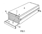
- FIG. 1 is an isometric view of a bank-note cassette having a shutter door made in accordance with the invention
- bank-note cassette shown in Figure 1 is shown in more detail in our published UK Patent Specification No. 2039264A.
- the cassette is in the form of a strong box 6 which has at one end a shutter 7 formed of a number of strips 8 made in accordance with the invention.
- the lateral ends of the strips forming the shutter are when the shutter is closed engaged in guides 9 and 10 at the sides-of the cassette.
- the guides are of U-shaped sections so as to receive the ends of the shutter.
- the cassette is arranged so that when it is put into an appropriate machine a pair of rods 11 and 12 enter the cassette and operate mechanism to open the shutter.
- FIGs 2 and 2A a single moulded plastic strip adapted to form a shutter in accordance with the invention.
- the strip 13 is shown broken into three parts for convenience of illustration but it will be appreciated that the three parts are injection moulded to form a single unitary strip with integral male and female connecting members 14 and 15 at each end of the strip as shown in Figure 2.
- These connecting members are formed adjacent a shoulder 16 so that when the connecting members are joined together the shoulder 16 prevents relative lateral movement of the strip because the inner surfaces of the female members 15 engage the shoulders 16 on adjacent strips.
- a recess 17 (Fig.2a) and.a corresponding extension portion 18 so that when the strips are engaged to form a shutter the portions 18 lie in adjacent recesses 17 on adjacent strips thus forming a uniform shutter surface and preventing or substantially preventing tampering with the shutter.
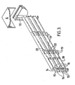
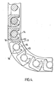
- FIG. 3 A portion of the guide 9 is shown in Fig. 3 and also somewhat diagrammatically in Figure 4 with one end of the shutter shown contained within the guide. Portions of the ends of the strips forming the shutter are shown broken away and in sections to illustrate the way in which the male and female members are contained totally within the guides 9 and 10 and to illustrate the way in which the strips bend to follow the contour of the guides.
- the male and female members at the ends of the shutter are contained within these guides and can be dimensioned so as to be a very close fit in the guides with virtually no play, the 'wear on the shutters is restricted.
- the injection moulded plastic strips are very inexpensive and thus the total cost of producing a shutter may be reduced by making use of this invention.
- the material used for the injection moulding of the strips is preferably glass filled acetal or nylon.
- the strips 13 may be reinforced by embedding elongated reinforcement members such as Nylon cord, metal strips, rods or wires or glass or other fibres in the strips 13.
- elongated reinforcement members such as Nylon cord, metal strips, rods or wires or glass or other fibres in the strips 13.
Landscapes
- Engineering & Computer Science (AREA)
- Structural Engineering (AREA)
- Architecture (AREA)
- Civil Engineering (AREA)
- Operating, Guiding And Securing Of Roll- Type Closing Members (AREA)
- Injection Moulding Of Plastics Or The Like (AREA)
- Securing Of Glass Panes Or The Like (AREA)
Abstract
Description
- This invention relates to a shutter of the kind which comprises a series of inter-connected strips which extend laterally of the shutter so as to provide a flexible form of shutter or door capable of negotiating bends during its opening and closing operation. Shutters of this kind are used as closures for boxes and containers such as cassettes containing bank-notes, vertical filing cabinets, and for doors for garages, lock-up shops etc.
- An object of this invention is to provide a shutter which is inexpensive to manufacture, has a minimum of parts, and is substantially.tamper-proof when used in appropriate circumstances such as when used as a cassette. door.
- In accordance with the present- invention there is a flexible shutter comprising a series of inter-connected strips which extend laterally of the shutter, each strip having at each end integral male and female connecting members whereby the strips may be joined in series to form the shutter, each strip also comprising a recess running the length of the strip adapted to receive a corresponding overlapping portion of an adjacent strip. The strips are . preferably individually formed by injection moulding. Preferably the individual strips are formed from plastics material.
- The strips may be reinforced by embedding reinforcement wires or reinforcement strips in the individual injection moulded plastic strips.
- Each of the strips may be formed with a protruding tongue and a recess so positioned that when the strips are joined at their ends the tongue of one strip enters the recess of an adjacent strip so as to interlock the strips to prevent tampering and to allow flexibility of the strips.
- Preferably also the male and female connecting members are formed adjacent shoulders at the ends of the strips so that when the male and female connecting members are engaged relative lateral movement of the strips is prevented.
- The shutter may be used as the door of a cassette, particularly a cassette intended to contain bank-notes, and in this case the ends of the strips forming the shutter are preferably engaged in guides at each side of the cassette so that the male and female connecting members are totally enclosed within the guides.
- In the accompanying drawings:-Figure 1 is an isometric view of a bank-note cassette having a shutter door made in accordance with the invention;
- Figure 2 shows one of the injection moulded strips which will form the shutter door;
- Figure 2A shows an enlarged view partly in section of the same strip;
- Figure 3 shows the way in which the individual strips of Figure 2 are assembled to form a shutter; and
- Figure 4 is a section through one end of an assembled shutter illustrating the inter-engaging male and female portions which are enclosed within a guide on the cassette.
- The bank-note cassette shown in Figure 1 is shown in more detail in our published UK Patent Specification No. 2039264A.
- The cassette is in the form of a
strong box 6 which has at one end ashutter 7 formed of a number ofstrips 8 made in accordance with the invention. The lateral ends of the strips forming the shutter are when the shutter is closed engaged inguides - The cassette is arranged so that when it is put into an appropriate machine a pair of
rods 11 and 12 enter the cassette and operate mechanism to open the shutter. - The full details of this cassette will not be described but they may be obtained by reference to our published UK Patent Specification 2039264A.
- In Figures 2 and 2A is shown a single moulded plastic strip adapted to form a shutter in accordance with the invention. In Figure 2A the
strip 13 is shown broken into three parts for convenience of illustration but it will be appreciated that the three parts are injection moulded to form a single unitary strip with integral male and female connectingmembers shoulder 16 so that when the connecting members are joined together theshoulder 16 prevents relative lateral movement of the strip because the inner surfaces of thefemale members 15 engage theshoulders 16 on adjacent strips. Throughout the length of the strip is formed a recess 17 (Fig.2a) and.acorresponding extension portion 18 so that when the strips are engaged to form a shutter theportions 18 lie inadjacent recesses 17 on adjacent strips thus forming a uniform shutter surface and preventing or substantially preventing tampering with the shutter. - To further strengthen the shutter and to assist in preventing tampering tongu l9:is formed on each strip and
corresponding recesses 20 so that when the strips are joined together thetongues 19 of all the strips engage inrecesses 20 of adjacent strip. This is best seen in Figure 3 where it is seen that several of the strips have been joined together by engaging the male and female inter-connecting members at their ends. The formation of the connecting members is such as to allow flexibility of the shutter, security in joining the strips to form the shutter and restriction of relative lateral movement of the strips. - When the shutter is used as the door of a cassette of the type shown in Figure 1 of the drawings the male and female
inter-connecting members guides - A portion of the
guide 9 is shown in Fig. 3 and also somewhat diagrammatically in Figure 4 with one end of the shutter shown contained within the guide. Portions of the ends of the strips forming the shutter are shown broken away and in sections to illustrate the way in which the male and female members are contained totally within theguides - Because the male and female members at the ends of the shutter are contained within these guides and can be dimensioned so as to be a very close fit in the guides with virtually no play, the 'wear on the shutters is restricted.
- Also by enclosing the inter-connecting male and female members totally in the guides it is very difficult for them to become disconnected or for anybody to attempt to disconnect them by tampering with the shutter.
- The injection moulded plastic strips are very inexpensive and thus the total cost of producing a shutter may be reduced by making use of this invention.
- The material used for the injection moulding of the strips is preferably glass filled acetal or nylon.
- The
strips 13 may be reinforced by embedding elongated reinforcement members such as Nylon cord, metal strips, rods or wires or glass or other fibres in thestrips 13.
Claims (8)
Priority Applications (3)
| Application Number | Priority Date | Filing Date | Title |
|---|---|---|---|
| GB08310887A GB2141471B (en) | 1983-04-21 | 1983-04-21 | Injection moulded slat for a shutter |
| DE8484305828T DE3474579D1 (en) | 1984-08-24 | 1984-08-24 | Injection moulded shutter |
| EP19840305828 EP0172953B1 (en) | 1983-04-21 | 1984-08-24 | Injection moulded shutter |
Applications Claiming Priority (2)
| Application Number | Priority Date | Filing Date | Title |
|---|---|---|---|
| GB08310887A GB2141471B (en) | 1983-04-21 | 1983-04-21 | Injection moulded slat for a shutter |
| EP19840305828 EP0172953B1 (en) | 1983-04-21 | 1984-08-24 | Injection moulded shutter |
Publications (2)
| Publication Number | Publication Date |
|---|---|
| EP0172953A1 true EP0172953A1 (en) | 1986-03-05 |
| EP0172953B1 EP0172953B1 (en) | 1988-10-12 |
Family
ID=26094103
Family Applications (1)
| Application Number | Title | Priority Date | Filing Date |
|---|---|---|---|
| EP19840305828 Expired EP0172953B1 (en) | 1983-04-21 | 1984-08-24 | Injection moulded shutter |
Country Status (2)
| Country | Link |
|---|---|
| EP (1) | EP0172953B1 (en) |
| GB (1) | GB2141471B (en) |
Cited By (3)
| Publication number | Priority date | Publication date | Assignee | Title |
|---|---|---|---|---|
| GB2288626A (en) * | 1994-04-22 | 1995-10-25 | Ra Extrusions Ltd | Slatted closure |
| EP1550625A3 (en) * | 2003-12-31 | 2005-09-28 | LG N-Sys. Inc. | Media cassette with internal lock |
| FR3136806A1 (en) * | 2022-06-20 | 2023-12-22 | Faurecia Interieur Industrie | Closing curtain of a receptacle comprising rigid articulated elements |
Families Citing this family (1)
| Publication number | Priority date | Publication date | Assignee | Title |
|---|---|---|---|---|
| US5236260A (en) * | 1992-06-26 | 1993-08-17 | Jackson Yu | Shutter with juxtaposed slats for a cabinet |
Citations (5)
| Publication number | Priority date | Publication date | Assignee | Title |
|---|---|---|---|---|
| CH332404A (en) * | 1955-10-17 | 1958-09-15 | Rolladenfabrik A Griesser Ag | Process for the production of roller shutters and roller shutters produced by this process |
| AT236093B (en) * | 1962-10-15 | 1964-10-12 | Klaus Braselmann K G | Strip-shaped hollow-chamber plastic profile |
| GB1046391A (en) * | 1963-01-01 | 1966-10-26 | John Percival Booth | Improvements in or relating to rolling shutters |
| DE7118130U (en) * | 1971-08-19 | Warema Renkhoff Kg | Locking on roller shutter shingles | |
| GB2039264A (en) * | 1978-12-08 | 1980-08-06 | De La Rue Crosfield | Security Cassettes |
Family Cites Families (6)
| Publication number | Priority date | Publication date | Assignee | Title |
|---|---|---|---|---|
| GB593961A (en) * | 1945-06-20 | 1947-10-30 | Maurice Henry Robin | Improvements in or relating to roll type closures |
| GB494255A (en) * | 1937-04-23 | 1938-10-24 | Charles Hirschhorn | Improvements in rolling shutters and the like and laths therefor |
| GB875884A (en) * | 1958-12-15 | 1961-08-23 | Mueller Hermann | Lattice blinds for windows, doors or the like |
| US3516473A (en) * | 1968-10-17 | 1970-06-23 | Louverdrape Inc | Interlocking cap for foldable door |
| GB1593003A (en) * | 1978-01-25 | 1981-07-15 | Theuerkauff E | Roller shutter |
| GB2055935B (en) * | 1979-08-08 | 1983-05-05 | Daiichi Giken Kk | Shutter capable of admitting light and air |
-
1983
- 1983-04-21 GB GB08310887A patent/GB2141471B/en not_active Expired
-
1984
- 1984-08-24 EP EP19840305828 patent/EP0172953B1/en not_active Expired
Patent Citations (5)
| Publication number | Priority date | Publication date | Assignee | Title |
|---|---|---|---|---|
| DE7118130U (en) * | 1971-08-19 | Warema Renkhoff Kg | Locking on roller shutter shingles | |
| CH332404A (en) * | 1955-10-17 | 1958-09-15 | Rolladenfabrik A Griesser Ag | Process for the production of roller shutters and roller shutters produced by this process |
| AT236093B (en) * | 1962-10-15 | 1964-10-12 | Klaus Braselmann K G | Strip-shaped hollow-chamber plastic profile |
| GB1046391A (en) * | 1963-01-01 | 1966-10-26 | John Percival Booth | Improvements in or relating to rolling shutters |
| GB2039264A (en) * | 1978-12-08 | 1980-08-06 | De La Rue Crosfield | Security Cassettes |
Cited By (3)
| Publication number | Priority date | Publication date | Assignee | Title |
|---|---|---|---|---|
| GB2288626A (en) * | 1994-04-22 | 1995-10-25 | Ra Extrusions Ltd | Slatted closure |
| EP1550625A3 (en) * | 2003-12-31 | 2005-09-28 | LG N-Sys. Inc. | Media cassette with internal lock |
| FR3136806A1 (en) * | 2022-06-20 | 2023-12-22 | Faurecia Interieur Industrie | Closing curtain of a receptacle comprising rigid articulated elements |
Also Published As
| Publication number | Publication date |
|---|---|
| GB2141471B (en) | 1986-07-02 |
| EP0172953B1 (en) | 1988-10-12 |
| GB8310887D0 (en) | 1983-05-25 |
| GB2141471A (en) | 1984-12-19 |
Similar Documents
| Publication | Publication Date | Title |
|---|---|---|
| EP0543737B1 (en) | Reclosable plastic bag with sliderless zipper | |
| EP0276926A1 (en) | Clips | |
| EP0223760A1 (en) | Seal for a box enclosing a compact disc or tape cassette | |
| EP0363121A2 (en) | Lockable buckle | |
| US5871243A (en) | Tamper deterrent wire seal | |
| EP1028899B1 (en) | Hinged clip | |
| EP0807735A2 (en) | Anti-theft device applicable to containers of articles | |
| EP0172953B1 (en) | Injection moulded shutter | |
| EP0285720B1 (en) | Security box having sliding closure | |
| BG63670B1 (en) | Coded security seal | |
| EP0045164A1 (en) | Improvements in security seals | |
| US4618070A (en) | Injection moulded shutter | |
| EP0045775B1 (en) | Injection moulded bag closure | |
| GB2592037A (en) | Storage apparatus | |
| GB2163707A (en) | Security tie | |
| GB2306203A (en) | Cable retention device | |
| US12039822B2 (en) | Storage apparatus | |
| EP1311170B1 (en) | Security device | |
| JPS6183791A (en) | Bending shutter | |
| US4520534A (en) | Sliding closure assemblies | |
| EP0422905B1 (en) | Label holder for closing and sealing bags and the like, and security seal suitable for use therewith | |
| EP0070611B1 (en) | Plastic container with hinged plastic lid | |
| GB2161138A (en) | Security bags | |
| KR850002852Y1 (en) | Slide fastener | |
| GB2605353A (en) | Storage Apparatus |
Legal Events
| Date | Code | Title | Description |
|---|---|---|---|
| PUAI | Public reference made under article 153(3) epc to a published international application that has entered the european phase |
Free format text: ORIGINAL CODE: 0009012 |
|
| AK | Designated contracting states |
Kind code of ref document: A1 Designated state(s): CH DE FR GB IT LI SE |
|
| 17P | Request for examination filed |
Effective date: 19860808 |
|
| 17Q | First examination report despatched |
Effective date: 19871102 |
|
| GRAA | (expected) grant |
Free format text: ORIGINAL CODE: 0009210 |
|
| AK | Designated contracting states |
Kind code of ref document: B1 Designated state(s): CH DE FR GB IT LI SE |
|
| PG25 | Lapsed in a contracting state [announced via postgrant information from national office to epo] |
Ref country code: IT Free format text: LAPSE BECAUSE OF FAILURE TO SUBMIT A TRANSLATION OF THE DESCRIPTION OR TO PAY THE FEE WITHIN THE PRESCRIBED TIME-LIMIT;WARNING: LAPSES OF ITALIAN PATENTS WITH EFFECTIVE DATE BEFORE 2007 MAY HAVE OCCURRED AT ANY TIME BEFORE 2007. THE CORRECT EFFECTIVE DATE MAY BE DIFFERENT FROM THE ONE RECORDED. Effective date: 19881012 |
|
| REF | Corresponds to: |
Ref document number: 3474579 Country of ref document: DE Date of ref document: 19881117 |
|
| ET | Fr: translation filed | ||
| PLBE | No opposition filed within time limit |
Free format text: ORIGINAL CODE: 0009261 |
|
| STAA | Information on the status of an ep patent application or granted ep patent |
Free format text: STATUS: NO OPPOSITION FILED WITHIN TIME LIMIT |
|
| PG25 | Lapsed in a contracting state [announced via postgrant information from national office to epo] |
Ref country code: GB Effective date: 19890824 |
|
| PG25 | Lapsed in a contracting state [announced via postgrant information from national office to epo] |
Ref country code: SE Effective date: 19890825 |
|
| PG25 | Lapsed in a contracting state [announced via postgrant information from national office to epo] |
Ref country code: LI Effective date: 19890831 Ref country code: CH Effective date: 19890831 |
|
| 26N | No opposition filed | ||
| GBPC | Gb: european patent ceased through non-payment of renewal fee | ||
| PG25 | Lapsed in a contracting state [announced via postgrant information from national office to epo] |
Ref country code: FR Effective date: 19900427 |
|
| REG | Reference to a national code |
Ref country code: CH Ref legal event code: PL |
|
| PG25 | Lapsed in a contracting state [announced via postgrant information from national office to epo] |
Ref country code: DE Effective date: 19900501 |
|
| REG | Reference to a national code |
Ref country code: FR Ref legal event code: ST |
|
| EUG | Se: european patent has lapsed |
Ref document number: 84305828.0 Effective date: 19900418 |