EP0172488B1 - Contact arrangement for a current limiting circuit breaker - Google Patents
Contact arrangement for a current limiting circuit breaker Download PDFInfo
- Publication number
- EP0172488B1 EP0172488B1 EP85109862A EP85109862A EP0172488B1 EP 0172488 B1 EP0172488 B1 EP 0172488B1 EP 85109862 A EP85109862 A EP 85109862A EP 85109862 A EP85109862 A EP 85109862A EP 0172488 B1 EP0172488 B1 EP 0172488B1
- Authority
- EP
- European Patent Office
- Prior art keywords
- movable contact
- contact
- movable
- electromagnet
- arms
- Prior art date
- Legal status (The legal status is an assumption and is not a legal conclusion. Google has not performed a legal analysis and makes no representation as to the accuracy of the status listed.)
- Expired
Links
- 230000005520 electrodynamics Effects 0.000 claims abstract description 14
- 238000004804 winding Methods 0.000 claims description 29
- 230000000007 visual effect Effects 0.000 claims description 5
- 239000004020 conductor Substances 0.000 abstract description 10
- 238000000926 separation method Methods 0.000 description 5
- 239000007858 starting material Substances 0.000 description 5
- 238000006073 displacement reaction Methods 0.000 description 3
- 238000004140 cleaning Methods 0.000 description 2
- 230000015572 biosynthetic process Effects 0.000 description 1
Images


Classifications
-
- H—ELECTRICITY
- H01—ELECTRIC ELEMENTS
- H01H—ELECTRIC SWITCHES; RELAYS; SELECTORS; EMERGENCY PROTECTIVE DEVICES
- H01H77/00—Protective overload circuit-breaking switches operated by excess current and requiring separate action for resetting
- H01H77/02—Protective overload circuit-breaking switches operated by excess current and requiring separate action for resetting in which the excess current itself provides the energy for opening the contacts, and having a separate reset mechanism
- H01H77/10—Protective overload circuit-breaking switches operated by excess current and requiring separate action for resetting in which the excess current itself provides the energy for opening the contacts, and having a separate reset mechanism with electrodynamic opening
-
- H—ELECTRICITY
- H01—ELECTRIC ELEMENTS
- H01H—ELECTRIC SWITCHES; RELAYS; SELECTORS; EMERGENCY PROTECTIVE DEVICES
- H01H71/00—Details of the protective switches or relays covered by groups H01H73/00 - H01H83/00
- H01H71/04—Means for indicating condition of the switching device
-
- H—ELECTRICITY
- H01—ELECTRIC ELEMENTS
- H01H—ELECTRIC SWITCHES; RELAYS; SELECTORS; EMERGENCY PROTECTIVE DEVICES
- H01H89/00—Combinations of two or more different basic types of electric switches, relays, selectors and emergency protective devices, not covered by any single one of the other main groups of this subclass
- H01H89/06—Combination of a manual reset circuit with a contactor, i.e. the same circuit controlled by both a protective and a remote control device
- H01H89/08—Combination of a manual reset circuit with a contactor, i.e. the same circuit controlled by both a protective and a remote control device with both devices using the same contact pair
-
- H—ELECTRICITY
- H01—ELECTRIC ELEMENTS
- H01H—ELECTRIC SWITCHES; RELAYS; SELECTORS; EMERGENCY PROTECTIVE DEVICES
- H01H1/00—Contacts
- H01H1/12—Contacts characterised by the manner in which co-operating contacts engage
- H01H1/14—Contacts characterised by the manner in which co-operating contacts engage by abutting
- H01H1/20—Bridging contacts
- H01H2001/2091—Bridging contacts having two pivotally and electrically connected halve bridges
Definitions
- the invention relates to current limiting circuit breakers having contact arms that are arranged for mutual electrodynamic repulsion independently of the operating mechanism upon occurrence of a short circuit current fault. Some means must be provided to close the circuit breaker contacts after the fault has cleared, as well as to visually indicate the condition of the contacts so that an operator could observe whether the contacts are either open or closed without having to disassemble the breaker housing. It is also advantageous, with state-of-the-art circuit breakers, to employ two pairs of circuit interrupting contacts to interrupt the current with the formation of a separate pair of arcs and a separate pair of arc chutes for extinguishing the arcs.
- One object of the invention is to provide two pairs of circuit interrupting contacts operable by means of short circuit current to open both contact pairs independently of the operating mechanism.
- a further object of the invention is to provide a contact arrangement wherein contact separation is provided manually.
- Another object of the invention is to provide a remotely operable electromagnet in a current limiting circuit breaker containing at least a pair of circuit interrupting contacts to allow the breaker to operate as a remotely controlled electrical switching device, for example, an integrated combination motor starter.
- a further object is to provide an indicating arrangement for visual indication of the open and closed condition of the contacts.
- both the movable contact arms (55, 56) and the movable supports (70, 71) are pivotted about fixed pivots (62, 63), so that at the time of the contact closure there is just a closing or engaging movement of the movable contacts (57, 58) against the fixed contacts (59, 60) and no provision for the movable and the fixed contacts to rub against each other in order to provide contact cleaning.
- the invention is characterized by an additional electromagnet operatively connected with one of said movable contact arms whereby said one movable contact arm is held in an open position when said electromagnet is de-energized and said one movable contact arm returns to a closed position when said electromagnet is energized and the operating levers are set for the contact closure.
- the invention is characterized in that the additional electromagnet is operativelly connected with both said movable contact arms , whereby said movable contact arms return to a closed position when said electromagnet is energized and the operating levers are set for the contact closure.
- the invention is characterized in that one of the two fixed contact arms is made movable rotating around a pin connected to the structure, placed against a spring, said contact arrangement consisting of a first movable contact arm carrying a first movable contact, a second movable contact arm, carrying a second movable contact and series connected with a third contact arm, carrying a third movable contact, a fixed contact arm, carrying a fixed contact, and arranged for electrodynamic repulsion between said first and said second contact arms on one side, and between said third and said fixed contact arms on the other side, upon short circuit current through said movable and fixed contacts, and comprising in combination: a pair of operating levers connected with said second and third movable contact arms and adapted for manual operation by means of a push rod, said push rod being pivotally connected with said operating levers by means of a pair of connecting rods, said push rod intended to be actuated by a manually operated mechanism.
- the invention is further characterized by an electromagnet operatively connected with said first movable contract arm whereby said movable contact arm is held in an open position when said electromagnet is de-energized and said movable contact arm returns to a closed position when said electromagnet is energized and the operating levers are set for the contact closure.
- Fig. 1 contains a circuit breaker module 10 which generally houses the circuit breaking components of the current limiter of the invention and is enclosed within an insulating housing 11. Electrical connection is made with the module 10 by means of a conductor 12 which connects a line terminal 13 with a first fixed contact arm 14 which supports a first fixed contact 14a.
- a first movable contact arm 16 abutting a stop 17 integral with a first lever 32 supports a first movable contact 16a which conducts current through a flexible braid 18 to a second movable contact arm 20, abutting a stop 21 integral with a second lever 34, and carrying a second movable contact 20a.
- the current flows through a second fixed contact 22a and a second fixed contact arm 22 out to a load terminal screw 25 and load conductor 26 over a conductor 24.
- the two movable contact arms 16, 20 are rotatably mounted within the module 10 by means of pivots 28, 30 attached to the first and second levers 32, 34 which in turn are rotatably mounted within the module by means of pivots 36 and 38.
- the movable contact arms 16, 20 are free to rotate independently of levers 32, 34 upon occurrence of a short circuit current generating opposed electrodynamic repulsion forces between the first movable contact arm 16 and first fixed contact arm 14 causing the first movable contact arm and first movable contact to move to the open position against stops 84, 85 as indicated in phantom, respectively.
- the second movable contact arm 20 is also free to rotate against stops 86, 87 in a similar manner.
- the first movable contact arm return spring 60 is placed between a retainer 62 on the first lever 32 to bias the first movable contact arm in a closed position and to hold the first movable contact 16a against the first fixed contact 14a for good electrical flow therebetween.
- the second movable contact arm return spring 64 is placed between a retainer 66 on the second lever 34 to bias the second movable contact arm in a closed position and to hold the second movable contact 20a against the second fixed contact 22a for good electrical flow therebetween.
- the first and second levers 32, 34 are caused to rotate about their pivots 36, 38 by action of a push rod 50 pivotally connected with a pair of connecting rods 40, 42 by means of a pivot 48.
- the connecting rods in turn are pivotally connected to the first and second levers 32, 34 by means of pivots 44 and 46 respectively.
- the push rod 50 is manually operated by a traditional mechanism (not shown) working through a rod 56 which is operably connected with the push rod by means of a slot 52 and a pin 54. As indicated in Fig.
- a first arc chute 70 containing a plurality of arc plates 72 is arranged ahead of the first fixed and movable contacts 14a, 16a to cool and de-ionize any arc which occurs upon their separation and a second chute 80 is arranged ahead of the second fixed and movable contacts 22a, 20a consisting of a plurality of arc plates 82 to cool and deionise any arc which occurs upon their separation.
- An actuating electromagnet 120 is shown in Fig. 2 within an electromagnet module 100 consisting of an isolating case 110 arranged above the housing sidewall 11a shown in Fig. 1 which contains the same circuit breaker module 10 referred to earlier with reference to Fig. 1 and wherein just the contact arms 14 and 16 have been depicted for semplicity.
- a terminal 113 is connected with the circuit conductor 12 by means of a conductor 112.
- the electromagnet 120 consists of a winding 124 arranged around a fixed core 126 fixedly attached to a support 122 and a movable armature 128 biased within the winding by means of a spring 130.
- a bracket 132 on the armature connects with an operating lever 136 by means of a pin 134 at one end and the other end of the lever is supported by means of a pin 138.
- Connection is made between a push rod 140 and the operating lever 136 by means of a pin 137 fixedly attached to the operating lever and captured within a slot 139 formed within the push rod 140.
- the push rod operates on one of the movable contact arms, e.g. the arm 16 depicted in Fig.
- the electromagnet 120 can be arranged with respect to the winding 124 and the spring 130 to either move the operating lever 136 in a downard direction when energized to open the first fixed and movable contacts 14a, 16a or to move up the lever 136, closing the contacts, when energized and when the push rod 50 of the circuit breaker module 10 has rotated the levers 32 and 34 to close both the contact pairs 14a, 16a and 20a, 22a (see Fig. 1).
- a flag 146 supported on an extension 145 of the push rod 140 is arranged relative to a viewing window 148 to indicate the open and closed conditions of the movable contact arm as well as of the contacts.
- the spring 130 is arranged to hold the operating lever 136 downard forcing pin 137, push rod 140 and first movable contact arm 16 in a downard direction to separate contacts 14a, 16a as soon as the winding 124 becomes de-energized.
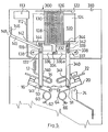
- Fig. 3 contains a circuit breaker contact arrangement similar to that of Fig. 1 operatively connected with an electromagnet module 100 similar to that shown in Fig. 2 which is arranged to hold the armature 128 against the fixed core 126 as long as the winding 124 is energized. Once the winding becomes de-energized the armature is forced downard under the urgence of the spring 130 to separate the contacts 14a, 16a. Thus the contacts 14a, 16a are capable of becoming separated upon occurrence of a short circuit current as described earlier as well as by de-energizing the winding 124. As above stated, this arrangement differs somewhat from that depicted in Figgs.
- Fig. 4 shows a contact arrangement similar to that depicted in Fig. 2 with the electromagnetic module 200 arranged along the circuit breaker insulative housing and with a terminal 113 connecting with the first fixed contact arm 14 by means of a conductor 112 and a conductor 12. Electrical connection through the circuit is provided by means of the first fixed and movable contacts 14a, 16a and the first movable contact arm 16 pivotally arranged for opening the contacts by means of pivot 28.
- the contacts are capable of electrodynamic separation by flow of short circuit current through the first fixed contact arm 14 and the first movable contact arm 16 in opposite directions.
- the contacts can also be opened and closed by means of push rod 140 which contacts a pin 90 centrally located on the movable contact arm 16 by means of the radius 141 formed at the end of the push rod in the same manner described earlier with reference to Fig. 2.
- a flag 146 connects with the push rod by means of extension 145 and is similarly arranged relative to window 148 to indicate the open and the closed conditions of the contacts.
- An electromagnet 220 consisting of a winding 224 arranged within an isolating case 210 around a fixed core 226 and a movable armature 228 controls the operation of the contacts by connection with the push rod by means of a bellcrank lever 236 which is pivotally arranged within the isolating case 210 by means of pivot 238.
- One end of the lever 236 is connected with the armature by means of a bracket 232, arm 235 and connector pin 234.
- the other end of the lever has a pin 137 fixedly attached to the lever and captured within a slot 139 formed within the push rod 140 as indicated.
- Energizing winding 224 holds armature 228 in contact with the fixed core 226 against the bias provided by a spring 230 which is anchored to the support 222.
- the armature 228 moves forward away from the fixed core 226 under the urgence of spring 230 causing arm 235 to rotate the lever 236 downward and forcing the push rod 140 to move the first movable contact arm downwardly to separate the contacts 14a, 16a independently of the condition of push rod 50 (Fig.
- a contact arrangement is shown in Fig. 5 wherein both the first movable contact arm 16 and the second movable contact arm 20 are controllable by means of the electromagnet 120 within an electromagnetic module 300 which is enclosed within an isolating case 310.
- the contacts are electrically connected with an external circuit by means of terminal 113 which connects with the first fixed contact arm 14 by means of conductors 12 and 112 as indicated.
- a flag 146 visually accessed by means of a window 148 shows the conditions of the contacts.
- both the first and second movable contact arms are capable of cooperation by electrodynamic repulsion against the holding force provided by their respective springs 60, 64.
- both movable contact arms are also capable of being operated by means of the electromagnet which is operatively connected to identical push rod 140, 340 which respectively contact pins 90, 91 on the movable contact arms by means of radii 141 and 341 forced on the ends of the push rods.
- the opposite end of the push rods connect with operating levers 336 and 336a by means of slots 139, 339 formed within the push rods and pins 137, 337 fixedly attached to the levers.
- the ends of the levers are supported by a pair of pins 138, 338 and the center of the levers are connected with an armature bracket 332 by means of a common pivot 334.
- the armature 128 When the winding 124 is energized, the armature 128 is held against the fixed core 126 against the bias of spring 130. When the winding 124 is de-energized the armature 128 moves downward under the urgence of spring 130 forcing levers 336 and 336a and push rods 140, 340 to move downward against the first and second movable contact arms 16, 20 separating their respective contacts independently of the condition of push rod 50 (Fig. 1). When the winding 124 is again energized, the armature 128 is drawn back to the fixed core 126 carrying the levers 336 and 336a and push rods 140, 340 in the upwards direction with the cooperation of springs 142, 342 held at their ends by means of supports 144 and 344. It is thus seen that the contacts are capable of electrodynamic separation under short circuit current conditions as well as being both opened and closed by means of the electromagnet 120 which is a desirable feature when the contact arrangement is used both as a circuit breaker and also as an integrated combination motor starter.
- FIG. 6 A further embodiment of the contact arrangemen of the invention is shown in Fig. 6 wherein the electromagnetic module 400 within isolating case 410 is arranged above the housing sidewall 11a. Electrical connection with a pair of movable contact arms 15, 16 supporting movable contacts 15a, 16a is made by means of terminal 113, conductors 112, 411 and braid 411a.
- the contact arms are arranged to open by means of electrodynamic repulsion whereby the movable contact arm 15 is rotated about pivot 15b against a stop 180 in opposition to the bias of a contact spring 442 which is fixedly attached to a support 444 at one end and to the movable contact arm 15 at an opposite end.
- the position of the contacts is indicated by means of a flag 446 visible through a window 448 and operatively connected with the contact arm by means of extension 445, rod 440, slot 441 and pin 90a as indicated.
- the other pair of contacts 20a, 22a are carried by movable contact arm 20 and fixed contact arm 22, respectively.
- the movable contact arms 16, 20 are carried by first and second levers 32, 34 which in turn are pivotally connected with push rod 50 by means of connecting rods 40 and 42.
- the fixed contact arm 22 of Fig. 6 can be replaced with a movable contact arm, similar to the contact arm 15, and the lever 436 and the rod 440 can be duplicated in a way similar to that of Fig. 5, allowing the opening of both the contact pairs when the electromagnet 420 is de-energized.
Landscapes
- Physics & Mathematics (AREA)
- Electromagnetism (AREA)
- Breakers (AREA)
- Emergency Protection Circuit Devices (AREA)
- Driving Mechanisms And Operating Circuits Of Arc-Extinguishing High-Tension Switches (AREA)
Abstract
Description
- The invention relates to current limiting circuit breakers having contact arms that are arranged for mutual electrodynamic repulsion independently of the operating mechanism upon occurrence of a short circuit current fault. Some means must be provided to close the circuit breaker contacts after the fault has cleared, as well as to visually indicate the condition of the contacts so that an operator could observe whether the contacts are either open or closed without having to disassemble the breaker housing. It is also advantageous, with state-of-the-art circuit breakers, to employ two pairs of circuit interrupting contacts to interrupt the current with the formation of a separate pair of arcs and a separate pair of arc chutes for extinguishing the arcs.
- One object Of the invention is to provide two pairs of circuit interrupting contacts operable by means of short circuit current to open both contact pairs independently of the operating mechanism.
- A further object of the invention is to provide a contact arrangement wherein contact separation is provided manually.
- "Another object of the invention is to provide a remotely operable electromagnet in a current limiting circuit breaker containing at least a pair of circuit interrupting contacts to allow the breaker to operate as a remotely controlled electrical switching device, for example, an integrated combination motor starter.
- A further object is to provide an indicating arrangement for visual indication of the open and closed condition of the contacts.
- In the prior art there are many contact arrangements for current limiting circuit breakers, such as those disclosed by FR-A-2 124 380. In this publication, specifically at figures 6 to 8, there is disclosed a contact arrangement essentially provided with movable contact arms (55, 56) pivotable about fixed pivots (62, 63), together but independently of movable supports (70, 71) supporting compressive spring means (64, 65) connected between said contact arms (55, 56) and said movable supports (70, 71) for providing a pushing bias therebetween, the assembly of the contact arms, the movable supports and the spring means acting as overcenter means to allow the closure of movable contacts (57, 58) against fixed contacts (59, 60) in the usual closure step (Fig. 6) and to maintain open the contacts, after a repulsion due to short circuit current, owing to the above overcenter feature (Fig. 7). Every external actuation to controllably open or close the contacts is provided by two rods (72, 73) connected between said movable supports (70, 71) and a common translating member (74) in turn actuated by a lever (75) connected to a shaft (76) (refer to Fig. 6 for contact closure and to Fig. 8 for opening), being in particular the contact opening provided by the operation of two protrusions (79, 80) integrally built with the supports (70, 71) against the movable contact arms (55, 56).
- In such a prior art, both the movable contact arms (55, 56) and the movable supports (70, 71) are pivotted about fixed pivots (62, 63), so that at the time of the contact closure there is just a closing or engaging movement of the movable contacts (57, 58) against the fixed contacts (59, 60) and no provision for the movable and the fixed contacts to rub against each other in order to provide contact cleaning.
- It is a specific object of the present invention to provide in a contact arrangement such a contact cleaning by means of reciprocal rubbing, by employing a contact arrangement for a current limiting circuit breaker consisting in at least a module comprising two movable contacts on two movable contact arms electrically connected in series and arranged for electrodynamic repulsion with respect to two fixed contacts on two fixed contact arms upon short circuit current through said two movable and said two fixed contacts, characterized by a pair of operating levers containing movable pivots for said movable contact arms and rotating about two fixed pivots, said operating levers being adapted for manual operation by means of a push rod conntected to the operating levers by means of a pair of connecting rods, said push rod being intended to be actuated by a manually operated mechanism and further characterized by contact springs supported by the operating levers and holding said movable contact arms with their contacts in a closed position agaisnt the contacts of said fixed contact arms."
- In a further preferred embodiment the invention is characterized by an additional electromagnet operatively connected with one of said movable contact arms whereby said one movable contact arm is held in an open position when said electromagnet is de-energized and said one movable contact arm returns to a closed position when said electromagnet is energized and the operating levers are set for the contact closure.
- In a still more preferred embodiment the invention is characterized in that the additional electromagnet is operativelly connected with both said movable contact arms , whereby said movable contact arms return to a closed position when said electromagnet is energized and the operating levers are set for the contact closure.
- In another alternative embodiment the invention is characterized in that one of the two fixed contact arms is made movable rotating around a pin connected to the structure, placed against a spring, said contact arrangement consisting of a first movable contact arm carrying a first movable contact, a second movable contact arm, carrying a second movable contact and series connected with a third contact arm, carrying a third movable contact, a fixed contact arm, carrying a fixed contact, and arranged for electrodynamic repulsion between said first and said second contact arms on one side, and between said third and said fixed contact arms on the other side, upon short circuit current through said movable and fixed contacts, and comprising in combination:
a pair of operating levers connected with said second and third movable contact arms and adapted for manual operation by means of a push rod, said push rod being pivotally connected with said operating levers by means of a pair of connecting rods, said push rod intended to be actuated by a manually operated mechanism. - In a still preferred embodiment the invention is further characterized by an electromagnet operatively connected with said first movable contract arm whereby said movable contact arm is held in an open position when said electromagnet is de-energized and said movable contact arm returns to a closed position when said electromagnet is energized and the operating levers are set for the contact closure.
- Fig. 1 is a side view of the current limiting contact arrangement according to the invention, operated by a mechanism of traditional type,not shown in the Figure;
- Figure 2 is a side view of a switching device, containing the contact arrangement, depicted in Fig. 1, provided with a first embodiment of additional actuating electromagnet to obtain the additional function of a motor starter, the whole device functioning as an integrated combination motor starter;
- Fig. 3 is a side view of an alternative embodiment of the switching device containing the current limiting contact arrangement provided with the same actuating electromagnet of Fig. 2 where no additional force is required from the operating mechanism due to the application of the actuating electromagnet;
- Fig. 4 is a side view of the switching device containing the current limiting contact arrangement provided with an alternative embodiment of actuating electromagnet;
- Fig. 5 is a side view of the switching device containing the current limiting contact arrangement provided with an actuating electromagnet operating on two pairs of separable contacts;
- Fig. 6 is an alternate variation of the contact arrangement depicted in Fig. 1 provided in a further embodiment of a switching device containing an actuating electromagnet where again no additional force is required from the operating mechanism due to the application of the actuating electromagnet.
- Fig. 1 contains a
circuit breaker module 10 which generally houses the circuit breaking components of the current limiter of the invention and is enclosed within aninsulating housing 11. Electrical connection is made with themodule 10 by means of aconductor 12 which connects aline terminal 13 with a first fixedcontact arm 14 which supports a first fixedcontact 14a. A firstmovable contact arm 16 abutting astop 17 integral with afirst lever 32 supports a firstmovable contact 16a which conducts current through aflexible braid 18 to a secondmovable contact arm 20, abutting astop 21 integral with asecond lever 34, and carrying a secondmovable contact 20a. The current flows through a second fixedcontact 22a and a second fixedcontact arm 22 out to aload terminal screw 25 and loadconductor 26 over aconductor 24. The twomovable contact arms module 10 by means ofpivots second levers pivots movable contact arms levers movable contact arm 16 and first fixedcontact arm 14 causing the first movable contact arm and first movable contact to move to the open position againststops 84, 85 as indicated in phantom, respectively. The secondmovable contact arm 20 is also free to rotate againststops arm return spring 60 is placed between aretainer 62 on thefirst lever 32 to bias the first movable contact arm in a closed position and to hold the firstmovable contact 16a against the first fixedcontact 14a for good electrical flow therebetween. The second movable contactarm return spring 64 is placed between aretainer 66 on thesecond lever 34 to bias the second movable contact arm in a closed position and to hold the secondmovable contact 20a against the second fixedcontact 22a for good electrical flow therebetween. - The first and
second levers pivots push rod 50 pivotally connected with a pair of connectingrods pivot 48. The connecting rods in turn are pivotally connected to the first andsecond levers pivots push rod 50 is manually operated by a traditional mechanism (not shown) working through arod 56 which is operably connected with the push rod by means of aslot 52 and apin 54. As indicated in Fig. 1, afirst arc chute 70 containing a plurality ofarc plates 72 is arranged ahead of the first fixed andmovable contacts second chute 80 is arranged ahead of the second fixed andmovable contacts arc plates 82 to cool and deionise any arc which occurs upon their separation. - An
actuating electromagnet 120 is shown in Fig. 2 within anelectromagnet module 100 consisting of anisolating case 110 arranged above thehousing sidewall 11a shown in Fig. 1 which contains the samecircuit breaker module 10 referred to earlier with reference to Fig. 1 and wherein just thecontact arms terminal 113 is connected with thecircuit conductor 12 by means of aconductor 112. Theelectromagnet 120 consists of a winding 124 arranged around a fixedcore 126 fixedly attached to asupport 122 and amovable armature 128 biased within the winding by means of aspring 130. Abracket 132 on the armature connects with anoperating lever 136 by means of apin 134 at one end and the other end of the lever is supported by means of apin 138. Connection is made between apush rod 140 and theoperating lever 136 by means of apin 137 fixedly attached to the operating lever and captured within aslot 139 formed within thepush rod 140. The push rod operates on one of the movable contact arms, e.g. thearm 16 depicted in Fig. 2, by contacting aradius 141 formed at one end of the push rod with apin 90 fixedly attached to a center region of the first movable contact arm to move the first movable contact arm downardly against the return bias provided to thepush rod 140 by means of the pushrod return spring 142 anchored to asupport 144. Theelectromagnet 120 can be arranged with respect to the winding 124 and thespring 130 to either move theoperating lever 136 in a downard direction when energized to open the first fixed andmovable contacts lever 136, closing the contacts, when energized and when thepush rod 50 of thecircuit breaker module 10 has rotated thelevers contact pairs flag 146 supported on anextension 145 of thepush rod 140 is arranged relative to aviewing window 148 to indicate the open and closed conditions of the movable contact arm as well as of the contacts. In the arrangement depicted in Fig. 2 thespring 130 is arranged to hold theoperating lever 136downard forcing pin 137,push rod 140 and firstmovable contact arm 16 in a downard direction to separatecontacts - When the
electromagnet 120 is de-energized, thesprings rod 140 against thepin 90 of thecontact arm 16, keeping thecontact pair push rod 50 is displaced in the upward direction making the twolevers contact pairs springs - As usually the
push rod 50 is moved by an operating mechanism of the type of an overcenter mechanism (not shown), it happens that sometimes, when the actuating force of the overcenter mechanism is still weak, the opposition of thesprings push rod 50, requiring some additional force from said operating mechanism. - In order to relieve this problem may be provided the alternative embodiment depicted in Fig. 3, wherein the rotating movement of the
lever 32 is prevented by aguide pin 61 fastened to a portion of thehousing sidewall 11a captured by aslot 63 within saidlever 32, so that the upward displacement of thepush rod 50 does not meet with the opposition of thesprings contact arms - Actually, Fig. 3 contains a circuit breaker contact arrangement similar to that of Fig. 1 operatively connected with an
electromagnet module 100 similar to that shown in Fig. 2 which is arranged to hold thearmature 128 against thefixed core 126 as long as the winding 124 is energized. Once the winding becomes de-energized the armature is forced downard under the urgence of thespring 130 to separate thecontacts contacts slot 63 in thefirst lever 32 which captures theguide pin 61 and by aslot 43 formed in the connectingrod 41 which joins thepush rod 50 to thefirst lever 32 by means ofpivot 44, so that thefirst lever 32 can not be rotated by the downward displacement of thepush rod 50. When thepush rod 50 is displaced in the downward direction pulling connectingrod 42 and rotating thesecond lever 34 clockwise around itspivot 38, just the secondmovable contact arm 20 is pulled by thestop 21 away from the second fixedcontact arm 22 and the secondmovable contact 20a is separated from the second fixedcontact 22a to interrupt the series current flow through the circuit. The downward movement of thepush rod 50moves connecting arm 41 alongslot 43 without rotating thefirst lever 32 in a counterclockwise opening direction due to the lost motion withinslots push rod 50 is displaced in the upward direction,pin 44 withinslot 43 forces lever 32 to move a little in a clockwise closing direction, assuring a strong enough closure force between thecontacts contacts pair electro magnet 120. Both contacts can be closed by the operation of the electromagnet as well as by the operation of thepush rod 50, but only thecontacts - Fig. 4 shows a contact arrangement similar to that depicted in Fig. 2 with the
electromagnetic module 200 arranged along the circuit breaker insulative housing and with aterminal 113 connecting with the first fixedcontact arm 14 by means of aconductor 112 and aconductor 12. Electrical connection through the circuit is provided by means of the first fixed andmovable contacts movable contact arm 16 pivotally arranged for opening the contacts by means ofpivot 28. The contacts are capable of electrodynamic separation by flow of short circuit current through the first fixedcontact arm 14 and the firstmovable contact arm 16 in opposite directions. The contacts can also be opened and closed by means ofpush rod 140 which contacts apin 90 centrally located on themovable contact arm 16 by means of theradius 141 formed at the end of the push rod in the same manner described earlier with reference to Fig. 2. Aflag 146 connects with the push rod by means ofextension 145 and is similarly arranged relative towindow 148 to indicate the open and the closed conditions of the contacts. Anelectromagnet 220 consisting of a winding 224 arranged within anisolating case 210 around a fixedcore 226 and amovable armature 228 controls the operation of the contacts by connection with the push rod by means of abellcrank lever 236 which is pivotally arranged within the isolatingcase 210 by means ofpivot 238. One end of thelever 236 is connected with the armature by means of abracket 232,arm 235 andconnector pin 234. The other end of the lever has apin 137 fixedly attached to the lever and captured within aslot 139 formed within thepush rod 140 as indicated. Energizing winding 224 holds armature 228 in contact with the fixedcore 226 against the bias provided by aspring 230 which is anchored to thesupport 222. When the winding 224 is de-energized, thearmature 228 moves forward away from the fixedcore 226 under the urgence ofspring 230 causingarm 235 to rotate thelever 236 downward and forcing thepush rod 140 to move the first movable contact arm downwardly to separate thecontacts spring 230 and returning the contacts to a closed condition by forcing the push rod upward in cooperation with the pushrod return spring 142. This arrangement not only allows the contacts to separate under short circuit conditions but also allows the contacts to be open and closed by means of theelectromagnet 220 allowing the circuit breaker to operate as an integrated combination motor starter. - A contact arrangement is shown in Fig. 5 wherein both the first
movable contact arm 16 and the secondmovable contact arm 20 are controllable by means of theelectromagnet 120 within anelectromagnetic module 300 which is enclosed within an isolatingcase 310. The contacts are electrically connected with an external circuit by means of terminal 113 which connects with the first fixedcontact arm 14 by means ofconductors flag 146 visually accessed by means of awindow 148 shows the conditions of the contacts. As also described earlier, both the first and second movable contact arms are capable of cooperation by electrodynamic repulsion against the holding force provided by theirrespective springs identical push rod radii operating levers slots pins armature bracket 332 by means of acommon pivot 334. When the winding 124 is energized, thearmature 128 is held against the fixedcore 126 against the bias ofspring 130. When the winding 124 is de-energized thearmature 128 moves downward under the urgence ofspring 130 forcinglevers rods movable contact arms armature 128 is drawn back to the fixedcore 126 carrying thelevers rods springs supports electromagnet 120 which is a desirable feature when the contact arrangement is used both as a circuit breaker and also as an integrated combination motor starter. - A further embodiment of the contact arrangemen of the invention is shown in Fig. 6 wherein the
electromagnetic module 400 within isolatingcase 410 is arranged above thehousing sidewall 11a. Electrical connection with a pair ofmovable contact arms movable contacts terminal 113,conductors 112, 411 andbraid 411a. The contact arms are arranged to open by means of electrodynamic repulsion whereby themovable contact arm 15 is rotated aboutpivot 15b against astop 180 in opposition to the bias of a contact spring 442 which is fixedly attached to a support 444 at one end and to themovable contact arm 15 at an opposite end. The position of the contacts is indicated by means of a flag 446 visible through a window 448 and operatively connected with the contact arm by means ofextension 445,rod 440,slot 441 andpin 90a as indicated. The other pair ofcontacts movable contact arm 20 and fixedcontact arm 22, respectively. Themovable contact arms second levers push rod 50 by means of connectingrods electrognet 420 with its winding 424 arranged around the fixedcore 426 andarmature 428 operates in the following manner. When the winding is energized, the armature pullsbracket 432 andlever 436, which are joined by means ofpivot 434, downwards against the bias ofspring 430 which is fixedly attached to support 422 at one end and to the armature at the other end. Themovable contact arm 15 is allowed to be closed by the urgence of contact spring 442 and the movement ofpin 90a withinslot 441. However, when the winding is de-energized, the armature is moved upwards under the urgence ofspring 430 which carries thelever 436 androd 440 which is attached to the rod bypivot 437 causing the lever to pivot counterclockwise about itspivot 438 and pulling themovable contact arm 15 andmovable contact 15a into the open position. It is noted that the contacts cannot be manually re-closed by operation of thepush rod 50 until the winding 424 is again energized to allow themovable contact arm 15 andmovable contact 15a to return to the downward contact closed position. - Of course, the fixed
contact arm 22 of Fig. 6 can be replaced with a movable contact arm, similar to thecontact arm 15, and thelever 436 and therod 440 can be duplicated in a way similar to that of Fig. 5, allowing the opening of both the contact pairs when theelectromagnet 420 is de-energized. - This embodiment of Fig. 6, either according to the solution having just one
movable contact arm 15 or according to the solution having two movable contact arms actuated by theelectromagnet 420, outstandingly relieves the problem of weak force of an overcenter mechanism mentioned in connection with the embodiment of Fig. 3.
Claims (26)
- A contact arrangement for a current limiting circuit breaker consisting in at least a module (10) comprising two movable contacts (16a, 20a) on two movable contact arms (16, 20) electrically connected in series and arranged for electrodynamic repulsion with respect to two fixed contacts (14a, 22a) on two fixed contact arms (14, 22) upon short circuit current through said two movable (16a, 20a) and said two fixed (14a, 22a) contacts, characterized by a pair of operating levers (32, 34) containing movable pivots (28, 30) for said movable contact arms (16, 20) and rotating about two fixed pivots (36, 38), said operating levers (32, 34) being adapted for manual operation by means of a push rod (50) connected to said operating levers (32, 34) by means of a pair of connecting rods (41, 42), said push rod (50) being intended to be actuated by a manually operated mechanism and further characterized by contact springs (60, 64) supported by the operating levers (32, 34) and holding said movable contact arms (16, 20) with their contacts (16a, 20a) in a closed position against the contacts of said fixed contact arms (14, 22).
- An electrical switching device, containing the contact arrangement of claim 1 characterized by an additional electromagnet (120, 220), contained in an electromagnet module (100, 200), operatively connected with one of said movable contact arms (16) whereby said one movable contact arm (16) is held in an open position when said electromagnet (120, 220) is de-energized and said one contact arm (16) returns to a closed position when said electromagnet (120, 220) is energized and the operating levers (32, 34) are set for the contact closure.
- The electrical switching device of Claim 2 characterized in that said electromagnet (120, 220) comprises a fixed core (126, 226) and an armature (128, 228) arranged within a winding (124, 224), said armature (128, 228) being operatively connected with said one movable contact arm (16) for operating said one movable contact arm (16) against the bias of said first contact spring (60).
- The electrical switching device of Claim 3 characterized in that said electromagnet (120, 220) further includes a spring (130, 230) biasing said armature (128, 228) away from said fixed core (126, 226) when said winding (124, 224) is de-energized.
- The electrical switching device of Claim 3 further characterized by an indicating flag (146) operatively connected with said one movable contact (16) arm for providing visual indication as to the open and closed position of said one movable arm (16).
- The electrical switching device of Claim 3 characterized in that said armature (128) is connected with a push rod (140) by means of a lever (136) whereby said push rod (140) holds said movable contact arm (16) in an open position under bias of said spring (130) until said winding (124) is energized to move said armature (128) into proximity with said fixed core (126) against said spring bias.
- The electrical switching device containing the contact arrangement of Claim 1 characterized in that the additional electromagnet (120) is operatively connected with both said movable contact arms (16, 20), whereby said movable contact arms return to a closed position when said electromagnet (120) is energized and the operating levers (32, 34) are set for the contact closure.
- The electrical switching device of Claim 7 characterized in that said electromagnet (120) comprises a fixed core (126) and an armature (120) arranged within a winding (124), said armature (128) being operatively connected with said movable contact arms (16, 20) for operating said movable contact arms (16, 20) against the bias of said first contact spring (60, 64).
- The electrical switching device of Claim 7 characterized in that said electromagnet (120) further includes a spring (130) biasing said armature (128) away from said fixed core (126) when said winding (124) is de-energized.
- The electrical switching device of Claim 7 further characterized by an indicating flag (146) operatively connected with one of said movable contact arms (16) for providing visual indication as to the open and closed position of said movable arms (16, 20).
- The electrical switching device of Claim 7 characterized in that said armature is connected with two push rods (140, 340) by means of two levers (336, 336a) whereby said push rods (140, 340) hold said movable contact arms (16, 20) in an open position under bias of said spring (130) until said winding (124) is energized to move said armature (128) into proximity with said fixed core (126) against said spring bias.
- The electrical switching device of Claim 2 characterized in that one of said operating levers (32) is provided with a slot (63) capturing a pin (61) fastened to a portion of a housing sidewall and is connected to one of said connecting rods (41) by means of a pin (44) on said one operating lever, captured within a slot (43) on said one conecting rod (41), for providing lost motion to said one connecting rod (41), whereby is prevented the movement of said one operating lever (32) and said one movable contact arm (16) is incapable of moving to a closed position by operation of said push rod (50) until said electromagnet (120) is de-energized.
- The electrical switching device of Claims 2 or 7 characterized in that said at least one lever comprises a bell-crank lever (236) pivotally connected with said armature (228) at one end and slidably connected with said at least one push rod (140) at an opposite end.
- The electrical switching device of Claim 13 characterized in that sad at least one bell-crank lever (236) is pivotally arranged intermediate both said ends for rotating in a first direction to move said at least one push rod (140) in a first direction and for rotating in a second direction to move said push rod in a second opposite direction.
- The contact arrangement of Claim 1 characterized in that one of the two fixed contact arms is made movable rotating around a pin (156) connected to the structure, placed against a spring (442), said contact arrangement consisting of a first movable contact arm (15) carrying a first movable contact (15a), a second movable contact arm (16), carrying a second movable contact (16a), and series connected with a third contact arm (20), carrying a third movable contact (20a), a fixed contact arm (22), carrying a fixed contact (22a), and arranged for electrodynamic repulsion between said first and said second contact arms (15, 16), on one side, and between said third and said fixed contact arms (20, 22), on the other side, upon short circuit current through said movable and fixed contacts, and comprising in combination:
a pair of operating levers (32, 34) connected with said second and third movable contact arms (16, 20) and adapted for manual operation by means of a push rod (50), said push rod (50) being pivotally connected with said operating levers by means of a pair of connecting rods (40, 42), intended said push rod to be actuated by a manually operated mechanism. - An electrical switching device containing the contact arrangement of Claim 15, further characterized by an electromagnet (420) operatively connected with said first movable contact arm (15) whereby said movable contact arm (15) is held in an open position when said electromagnet is de-energized and said movable contact arm (15) returns to a closed position when said electromagnet is energized and the operating levers (32, 34) are set for the contact closure.
- The contact arrangement of Claim 15 further characterized by two contact springs (60, 64) for holding said second and third movable contact arms (16, 20) in a closed position with respect to said first movable contact arm (15) and said fixed contact arm (22), respectively.
- The contact arrangement of Claim 15 further characterized by an electromagnet (420), contained in a module (400), operatively connected with said first movable contact arm (15) by means of a pull rod (440) preventing said contact arm (15) from returning to a closed position until said electromagnet (420) is de-energized.
- The contact arrangement of Claim 18, characterized in that said electromagnet (420) includes a fixed core (426), an armature (428) and a winding (424), said armature (428) being biased away from said core (426) by means of a spring (430) and being connected with said pull rod (440) by means of a lever (436) whereby said pull rod (440) holds said first movable contact (15) in an open position under bias of said spring (430) until said winding (424) is energized to move said armature (428) into proximity with said fixed core (426) against said spring bias.
- The contact arrangement of Claim 19, characterized by an indicating flag (446) connected with said pull rod (440) for providing visual indication as to the open and closed position of said first movable contact arm (15).
- The contact arrangement of Claim 1 characterized in that both fixed contact arms are made movable, each of them rotating around a pin (15b) connected to the structure, against a spring (442), said contact arrangement consisting of a first movable contact arm (15) carrying a first movable contact (15a), a second movable contact arm (16), carrying a second movable contact (16a), and series connected with a third contact arm (20), carrying a third movable contact (20a), a fourth movable contact arm, carrying a movable contact, and arranged for electrodynamic repulsion between said first and said second contact arms (15, 16) on one side and between said third and fourth contact arms on the other side upon short circuit current through said movable contacts, comprising in combination:
a pair of operating levers (32, 34) connected with said second and third movable contact arms (16, 20) and adapted for manual operation by means of a push rod (50), said push rod (50) being pivotally connected with said operating levers (32, 34) by means of a pair of connecting rods (40, 42), intended said push rod (50) to be actuated by a manually operated mechanism. - An electrical switching device containing the contact arrangement of Claim 21, further characterized by an electromagnet (420) operatively connected with said first and fourth movable contact arms whereby said movable contact arms are held in an open position when said electromagnet (420) is de-energized and said movable contact arms return to a closed position when said electromagnet (420) is energized.
- The contact arrangement of Claim 21 further characterized by two contact springs (60, 64) for holding said second and third movable contact arms (16, 20) in a closed position with respect to said first and fourth movable contact arms, respectively.
- The contact arrangement of Claim 21 further characterized by an electromagnet (420) operatively connected with said first and fourth movable contact arms by means of two pull rods preventing said contact arms from returning to a closed position until said electromagnet (420) is de-energized.
- The contact arrangement of Claim 24, characterized in that said electromagnet (420) includes a fixed core (426), an armature (428) and a winding (424), said armature (428) being biased away from said core (426) by means of a spring (430) and being connected with said two pull rods by means of two levers whereby said pull rods hold said first and fourth movable contact in an open position under bias of said spring (430) until said winding (424) is energized to move said armature (428) into proximity with said fixed core (426) against said spring bias (430).
- The contact arrangement of Claim 25 characterized by an indicating flag (446) connected with one of said pull rods (440) for providing visual indication as to the open and closed position of said first movable contact arm (15).
Priority Applications (1)
| Application Number | Priority Date | Filing Date | Title |
|---|---|---|---|
| AT85109862T ATE75345T1 (en) | 1984-08-14 | 1985-08-06 | CONTACT ARRANGEMENT FOR CURRENT-LIMITING CIRCUIT BREAKER. |
Applications Claiming Priority (2)
| Application Number | Priority Date | Filing Date | Title |
|---|---|---|---|
| IT8422405A IT1175633B (en) | 1984-08-14 | 1984-08-14 | Contact arrangement for current limiting circuit breaker |
| IT2240584 | 1984-08-24 |
Publications (3)
| Publication Number | Publication Date |
|---|---|
| EP0172488A2 EP0172488A2 (en) | 1986-02-26 |
| EP0172488A3 EP0172488A3 (en) | 1988-08-31 |
| EP0172488B1 true EP0172488B1 (en) | 1992-04-22 |
Family
ID=11195863
Family Applications (1)
| Application Number | Title | Priority Date | Filing Date |
|---|---|---|---|
| EP85109862A Expired EP0172488B1 (en) | 1984-08-14 | 1985-08-06 | Contact arrangement for a current limiting circuit breaker |
Country Status (5)
| Country | Link |
|---|---|
| US (1) | US4616198A (en) |
| EP (1) | EP0172488B1 (en) |
| AT (1) | ATE75345T1 (en) |
| DE (1) | DE3585897D1 (en) |
| IT (1) | IT1175633B (en) |
Families Citing this family (85)
| Publication number | Priority date | Publication date | Assignee | Title |
|---|---|---|---|---|
| ES2022388B3 (en) * | 1986-04-04 | 1991-12-01 | Telemecanique | ELECTRICAL SWITCH FOR PROTECTIVE APPARATUS, LIKE A CIRCUIT BREAKER. |
| US4879535A (en) * | 1987-05-26 | 1989-11-07 | Matsushita Electric Works, Ltd. | Remotely controllable circuit breaker |
| ATE115768T1 (en) * | 1987-10-01 | 1994-12-15 | Cge Spa | MANUALLY AND ELECTROMAGNETICALLY ACTUATED CONTACT ASSEMBLY FOR CURRENT-LIMITING SWITCHES. |
| US5818003A (en) * | 1996-02-08 | 1998-10-06 | Eaton Corporation | Electric switch with arc chute, radially converging arc splitter plates, and movable and stationary arc runners |
| IT1292453B1 (en) | 1997-07-02 | 1999-02-08 | Aeg Niederspannungstech Gmbh | ROTATING GROUP OF CONTACTS FOR HIGH FLOW SWITCHES |
| JP3359560B2 (en) * | 1998-03-13 | 2002-12-24 | 寺崎電気産業株式会社 | Circuit breaker |
| DE19819242B4 (en) * | 1998-04-29 | 2005-11-10 | Ge Power Controls Polska Sp.Z.O.O. | Thermomagnetic circuit breaker |
| US6114641A (en) * | 1998-05-29 | 2000-09-05 | General Electric Company | Rotary contact assembly for high ampere-rated circuit breakers |
| US6087913A (en) * | 1998-11-20 | 2000-07-11 | General Electric Company | Circuit breaker mechanism for a rotary contact system |
| US6037555A (en) * | 1999-01-05 | 2000-03-14 | General Electric Company | Rotary contact circuit breaker venting arrangement including current transformer |
| US6166344A (en) * | 1999-03-23 | 2000-12-26 | General Electric Company | Circuit breaker handle block |
| US6262872B1 (en) | 1999-06-03 | 2001-07-17 | General Electric Company | Electronic trip unit with user-adjustable sensitivity to current spikes |
| US6268991B1 (en) | 1999-06-25 | 2001-07-31 | General Electric Company | Method and arrangement for customizing electronic circuit interrupters |
| US6218917B1 (en) | 1999-07-02 | 2001-04-17 | General Electric Company | Method and arrangement for calibration of circuit breaker thermal trip unit |
| US6188036B1 (en) | 1999-08-03 | 2001-02-13 | General Electric Company | Bottom vented circuit breaker capable of top down assembly onto equipment |
| US6710988B1 (en) | 1999-08-17 | 2004-03-23 | General Electric Company | Small-sized industrial rated electric motor starter switch unit |
| US6252365B1 (en) | 1999-08-17 | 2001-06-26 | General Electric Company | Breaker/starter with auto-configurable trip unit |
| US6175288B1 (en) | 1999-08-27 | 2001-01-16 | General Electric Company | Supplemental trip unit for rotary circuit interrupters |
| US6396369B1 (en) | 1999-08-27 | 2002-05-28 | General Electric Company | Rotary contact assembly for high ampere-rated circuit breakers |
| US6232570B1 (en) | 1999-09-16 | 2001-05-15 | General Electric Company | Arcing contact arrangement |
| US6326869B1 (en) | 1999-09-23 | 2001-12-04 | General Electric Company | Clapper armature system for a circuit breaker |
| US6239395B1 (en) | 1999-10-14 | 2001-05-29 | General Electric Company | Auxiliary position switch assembly for a circuit breaker |
| US6229413B1 (en) | 1999-10-19 | 2001-05-08 | General Electric Company | Support of stationary conductors for a circuit breaker |
| US6317018B1 (en) | 1999-10-26 | 2001-11-13 | General Electric Company | Circuit breaker mechanism |
| US6232856B1 (en) | 1999-11-02 | 2001-05-15 | General Electric Company | Magnetic shunt assembly |
| US6377144B1 (en) | 1999-11-03 | 2002-04-23 | General Electric Company | Molded case circuit breaker base and mid-cover assembly |
| ES2249875T3 (en) | 1999-11-03 | 2006-04-01 | AEG NIEDERSPANNUNGSTECHNIK GMBH & CO. KG | ROTARY CONTACT ARM ARRANGEMENT FOR SWITCH. |
| US6300586B1 (en) | 1999-12-09 | 2001-10-09 | General Electric Company | Arc runner retaining feature |
| US6310307B1 (en) | 1999-12-17 | 2001-10-30 | General Electric Company | Circuit breaker rotary contact arm arrangement |
| US6172584B1 (en) | 1999-12-20 | 2001-01-09 | General Electric Company | Circuit breaker accessory reset system |
| US6184761B1 (en) | 1999-12-20 | 2001-02-06 | General Electric Company | Circuit breaker rotary contact arrangement |
| US6215379B1 (en) | 1999-12-23 | 2001-04-10 | General Electric Company | Shunt for indirectly heated bimetallic strip |
| US6281461B1 (en) | 1999-12-27 | 2001-08-28 | General Electric Company | Circuit breaker rotor assembly having arc prevention structure |
| US6346869B1 (en) | 1999-12-28 | 2002-02-12 | General Electric Company | Rating plug for circuit breakers |
| US6211758B1 (en) | 2000-01-11 | 2001-04-03 | General Electric Company | Circuit breaker accessory gap control mechanism |
| US6239677B1 (en) | 2000-02-10 | 2001-05-29 | General Electric Company | Circuit breaker thermal magnetic trip unit |
| US6429759B1 (en) | 2000-02-14 | 2002-08-06 | General Electric Company | Split and angled contacts |
| US6281458B1 (en) | 2000-02-24 | 2001-08-28 | General Electric Company | Circuit breaker auxiliary magnetic trip unit with pressure sensitive release |
| US6313425B1 (en) | 2000-02-24 | 2001-11-06 | General Electric Company | Cassette assembly with rejection features |
| US6204743B1 (en) | 2000-02-29 | 2001-03-20 | General Electric Company | Dual connector strap for a rotary contact circuit breaker |
| US6404314B1 (en) | 2000-02-29 | 2002-06-11 | General Electric Company | Adjustable trip solenoid |
| US6448521B1 (en) | 2000-03-01 | 2002-09-10 | General Electric Company | Blocking apparatus for circuit breaker contact structure |
| US6340925B1 (en) | 2000-03-01 | 2002-01-22 | General Electric Company | Circuit breaker mechanism tripping cam |
| US6346868B1 (en) | 2000-03-01 | 2002-02-12 | General Electric Company | Circuit interrupter operating mechanism |
| US6379196B1 (en) | 2000-03-01 | 2002-04-30 | General Electric Company | Terminal connector for a circuit breaker |
| US6459349B1 (en) | 2000-03-06 | 2002-10-01 | General Electric Company | Circuit breaker comprising a current transformer with a partial air gap |
| US6211757B1 (en) | 2000-03-06 | 2001-04-03 | General Electric Company | Fast acting high force trip actuator |
| US6366438B1 (en) | 2000-03-06 | 2002-04-02 | General Electric Company | Circuit interrupter rotary contact arm |
| US6496347B1 (en) | 2000-03-08 | 2002-12-17 | General Electric Company | System and method for optimization of a circuit breaker mechanism |
| US6429659B1 (en) | 2000-03-09 | 2002-08-06 | General Electric Company | Connection tester for an electronic trip unit |
| US6369340B1 (en) | 2000-03-10 | 2002-04-09 | General Electric Company | Circuit breaker mechanism for a contact system |
| US6403909B1 (en) | 2000-03-13 | 2002-06-11 | General Electric Company | Trip override for rotary breaker |
| US6218919B1 (en) | 2000-03-15 | 2001-04-17 | General Electric Company | Circuit breaker latch mechanism with decreased trip time |
| US6366188B1 (en) | 2000-03-15 | 2002-04-02 | General Electric Company | Accessory and recess identification system for circuit breakers |
| US6232859B1 (en) | 2000-03-15 | 2001-05-15 | General Electric Company | Auxiliary switch mounting configuration for use in a molded case circuit breaker |
| US6459059B1 (en) | 2000-03-16 | 2002-10-01 | General Electric Company | Return spring for a circuit interrupter operating mechanism |
| US6421217B1 (en) | 2000-03-16 | 2002-07-16 | General Electric Company | Circuit breaker accessory reset system |
| US6479774B1 (en) | 2000-03-17 | 2002-11-12 | General Electric Company | High energy closing mechanism for circuit breakers |
| US6472620B2 (en) | 2000-03-17 | 2002-10-29 | Ge Power Controls France Sas | Locking arrangement for circuit breaker draw-out mechanism |
| US6373010B1 (en) | 2000-03-17 | 2002-04-16 | General Electric Company | Adjustable energy storage mechanism for a circuit breaker motor operator |
| FR2806548B1 (en) | 2000-03-17 | 2002-08-23 | Ge Power Controls France | EXTRACTABLE MECHANISM FOR CIRCUIT BREAKERS |
| US6559743B2 (en) | 2000-03-17 | 2003-05-06 | General Electric Company | Stored energy system for breaker operating mechanism |
| US6388213B1 (en) | 2000-03-17 | 2002-05-14 | General Electric Company | Locking device for molded case circuit breakers |
| US6586693B2 (en) | 2000-03-17 | 2003-07-01 | General Electric Company | Self compensating latch arrangement |
| US6639168B1 (en) | 2000-03-17 | 2003-10-28 | General Electric Company | Energy absorbing contact arm stop |
| US6476698B1 (en) | 2000-03-17 | 2002-11-05 | General Electric Company | Convertible locking arrangement on breakers |
| US6747535B2 (en) | 2000-03-27 | 2004-06-08 | General Electric Company | Precision location system between actuator accessory and mechanism |
| US6995640B2 (en) | 2000-05-16 | 2006-02-07 | General Electric Company | Pressure sensitive trip mechanism for circuit breakers |
| US6373357B1 (en) | 2000-05-16 | 2002-04-16 | General Electric Company | Pressure sensitive trip mechanism for a rotary breaker |
| US6400245B1 (en) | 2000-10-13 | 2002-06-04 | General Electric Company | Draw out interlock for circuit breakers |
| US6429760B1 (en) | 2000-10-19 | 2002-08-06 | General Electric Company | Cross bar for a conductor in a rotary breaker |
| US6806800B1 (en) | 2000-10-19 | 2004-10-19 | General Electric Company | Assembly for mounting a motor operator on a circuit breaker |
| US6531941B1 (en) | 2000-10-19 | 2003-03-11 | General Electric Company | Clip for a conductor in a rotary breaker |
| US6362711B1 (en) | 2000-11-10 | 2002-03-26 | General Electric Company | Circuit breaker cover with screw locating feature |
| US6380829B1 (en) | 2000-11-21 | 2002-04-30 | General Electric Company | Motor operator interlock and method for circuit breakers |
| US6448522B1 (en) | 2001-01-30 | 2002-09-10 | General Electric Company | Compact high speed motor operator for a circuit breaker |
| KR100373441B1 (en) * | 2001-02-20 | 2003-02-25 | 현대중공업 주식회사 | Twin Repulsive Moving Breaking Contact Unit Of Molded Case Circuit Breaker |
| US6476337B2 (en) | 2001-02-26 | 2002-11-05 | General Electric Company | Auxiliary switch actuation arrangement |
| US6882258B2 (en) | 2001-02-27 | 2005-04-19 | General Electric Company | Mechanical bell alarm assembly for a circuit breaker |
| US6678135B2 (en) | 2001-09-12 | 2004-01-13 | General Electric Company | Module plug for an electronic trip unit |
| US6469882B1 (en) | 2001-10-31 | 2002-10-22 | General Electric Company | Current transformer initial condition correction |
| US6804101B2 (en) | 2001-11-06 | 2004-10-12 | General Electric Company | Digital rating plug for electronic trip unit in circuit breakers |
| US8836453B2 (en) * | 2011-10-07 | 2014-09-16 | Siemens Industry, Inc. | Electronic circuit breaker, electronic circuit breaker subassembly, circuit breaker secondary electrical contact assembly, and powering methods |
| CN104350560B (en) * | 2013-02-27 | 2017-09-15 | 通用电气公司 | Electric switching system |
| US10732223B2 (en) * | 2017-09-14 | 2020-08-04 | Schweitzer Engineering Laboratories, Inc. | Circuit breaker health monitoring |
Family Cites Families (6)
| Publication number | Priority date | Publication date | Assignee | Title |
|---|---|---|---|---|
| NL6810433A (en) * | 1967-07-24 | 1969-01-28 | ||
| DE2204662A1 (en) * | 1971-02-02 | 1972-08-10 | Sace Spa Construzione Elettrom | Current limit switch |
| FR2454174A1 (en) * | 1979-04-09 | 1980-11-07 | Merlin Gerin | CONTACTOR WITH FAST OPENING FAULT CONTROL |
| US4301342A (en) * | 1980-06-23 | 1981-11-17 | General Electric Company | Circuit breaker condition indicator apparatus |
| SE424242B (en) * | 1980-10-30 | 1982-07-05 | Asea Ab | ELECTROMAGNETIC MANOVATED ELECTRICAL SWITCH |
| FR2516304A1 (en) * | 1981-11-09 | 1983-05-13 | Telemecanique Electrique | MECHANICAL CONTROL SWITCH AND AUTOMATIC OPENING |
-
1984
- 1984-08-14 IT IT8422405A patent/IT1175633B/en active
-
1985
- 1985-07-11 US US06/754,042 patent/US4616198A/en not_active Expired - Fee Related
- 1985-08-06 DE DE8585109862T patent/DE3585897D1/en not_active Expired - Lifetime
- 1985-08-06 AT AT85109862T patent/ATE75345T1/en not_active IP Right Cessation
- 1985-08-06 EP EP85109862A patent/EP0172488B1/en not_active Expired
Also Published As
| Publication number | Publication date |
|---|---|
| IT1175633B (en) | 1987-07-15 |
| EP0172488A3 (en) | 1988-08-31 |
| US4616198A (en) | 1986-10-07 |
| DE3585897D1 (en) | 1992-05-27 |
| IT8422405A0 (en) | 1984-08-24 |
| ATE75345T1 (en) | 1992-05-15 |
| EP0172488A2 (en) | 1986-02-26 |
Similar Documents
| Publication | Publication Date | Title |
|---|---|---|
| EP0172488B1 (en) | Contact arrangement for a current limiting circuit breaker | |
| US3921109A (en) | Circuit-interrupter | |
| EP0309923B1 (en) | Improved contact arrangement for a current limiting circuit breaker adapted to be actuated both manually and by an actuating electromagnet | |
| US4532486A (en) | Remote controlled circuit breaker | |
| JPH07312133A (en) | Switch | |
| KR920006061B1 (en) | Molded case circuit breaker with single solenoid operator for rectilinear handle movement | |
| US4855698A (en) | Protective switching apparatus with remotely controlled opening and closing of the contacts | |
| GB1583716A (en) | Circuit breaker | |
| US4458225A (en) | Circuit breaker with independent magnetic and thermal responsive contact separation means | |
| US4987395A (en) | Circuit breaker alarm-switch operating apparatus | |
| JPH0765688A (en) | Contactor / protective relay type protection switch | |
| JPS62259319A (en) | Switching contactor protected from overcurrent | |
| AU2004201267B2 (en) | Remotely controllable circuit breaker including bypass magnet circuit | |
| US5614878A (en) | Two pole remote controlled circuit breaker | |
| JPH02100230A (en) | Remotely operated type circuit breaker | |
| US4220935A (en) | Current limiting circuit breaker with high speed magnetic trip device | |
| US5023583A (en) | Circuit breaker contact operating structure | |
| US4710738A (en) | Moulded case circuit breaker | |
| JPS61126728A (en) | Breaker having remote controlled switching function | |
| US4682132A (en) | Remote control circuit breaker having a retractable switch contact | |
| US4247745A (en) | Vacuum-type contactor assembly | |
| US6541727B2 (en) | Molded case circuit breaker including vacuum switch assembly | |
| GB2120013A (en) | Current-limiting circuit breaker apparatus | |
| US4739291A (en) | Magnetic vacuum circuit breaker | |
| US3940723A (en) | Instantaneously tripping device for circuit interrupter |
Legal Events
| Date | Code | Title | Description |
|---|---|---|---|
| PUAI | Public reference made under article 153(3) epc to a published international application that has entered the european phase |
Free format text: ORIGINAL CODE: 0009012 |
|
| AK | Designated contracting states |
Designated state(s): AT BE CH DE FR GB LI NL SE |
|
| PUAL | Search report despatched |
Free format text: ORIGINAL CODE: 0009013 |
|
| AK | Designated contracting states |
Kind code of ref document: A3 Designated state(s): AT BE CH DE FR GB LI NL SE |
|
| 17P | Request for examination filed |
Effective date: 19890222 |
|
| 17Q | First examination report despatched |
Effective date: 19901001 |
|
| GRAA | (expected) grant |
Free format text: ORIGINAL CODE: 0009210 |
|
| AK | Designated contracting states |
Kind code of ref document: B1 Designated state(s): AT BE CH DE FR GB LI NL SE |
|
| REF | Corresponds to: |
Ref document number: 75345 Country of ref document: AT Date of ref document: 19920515 Kind code of ref document: T |
|
| REF | Corresponds to: |
Ref document number: 3585897 Country of ref document: DE Date of ref document: 19920527 |
|
| ET | Fr: translation filed | ||
| PGFP | Annual fee paid to national office [announced via postgrant information from national office to epo] |
Ref country code: NL Payment date: 19920831 Year of fee payment: 8 |
|
| PGFP | Annual fee paid to national office [announced via postgrant information from national office to epo] |
Ref country code: AT Payment date: 19921016 Year of fee payment: 8 |
|
| PGFP | Annual fee paid to national office [announced via postgrant information from national office to epo] |
Ref country code: GB Payment date: 19921102 Year of fee payment: 8 |
|
| PLBE | No opposition filed within time limit |
Free format text: ORIGINAL CODE: 0009261 |
|
| STAA | Information on the status of an ep patent application or granted ep patent |
Free format text: STATUS: NO OPPOSITION FILED WITHIN TIME LIMIT |
|
| 26N | No opposition filed | ||
| PG25 | Lapsed in a contracting state [announced via postgrant information from national office to epo] |
Ref country code: GB Effective date: 19930806 Ref country code: AT Effective date: 19930806 |
|
| PG25 | Lapsed in a contracting state [announced via postgrant information from national office to epo] |
Ref country code: NL Effective date: 19940301 |
|
| GBPC | Gb: european patent ceased through non-payment of renewal fee |
Effective date: 19930806 |
|
| NLV4 | Nl: lapsed or anulled due to non-payment of the annual fee | ||
| PGFP | Annual fee paid to national office [announced via postgrant information from national office to epo] |
Ref country code: BE Payment date: 19940705 Year of fee payment: 10 |
|
| PGFP | Annual fee paid to national office [announced via postgrant information from national office to epo] |
Ref country code: CH Payment date: 19940826 Year of fee payment: 10 |
|
| PGFP | Annual fee paid to national office [announced via postgrant information from national office to epo] |
Ref country code: SE Payment date: 19940831 Year of fee payment: 10 |
|
| EAL | Se: european patent in force in sweden |
Ref document number: 85109862.4 |
|
| PG25 | Lapsed in a contracting state [announced via postgrant information from national office to epo] |
Ref country code: SE Effective date: 19950807 |
|
| PG25 | Lapsed in a contracting state [announced via postgrant information from national office to epo] |
Ref country code: LI Effective date: 19950831 Ref country code: CH Effective date: 19950831 Ref country code: BE Effective date: 19950831 |
|
| BERE | Be: lapsed |
Owner name: COMPAGNIA GENERALE ELETTROMECCANICA S.P.A. CGE Effective date: 19950831 |
|
| REG | Reference to a national code |
Ref country code: CH Ref legal event code: PL |
|
| EUG | Se: european patent has lapsed |
Ref document number: 85109862.4 |
|
| PGFP | Annual fee paid to national office [announced via postgrant information from national office to epo] |
Ref country code: FR Payment date: 20020717 Year of fee payment: 18 |
|
| PGFP | Annual fee paid to national office [announced via postgrant information from national office to epo] |
Ref country code: DE Payment date: 20031030 Year of fee payment: 19 |
|
| PG25 | Lapsed in a contracting state [announced via postgrant information from national office to epo] |
Ref country code: FR Free format text: LAPSE BECAUSE OF NON-PAYMENT OF DUE FEES Effective date: 20040430 |
|
| REG | Reference to a national code |
Ref country code: FR Ref legal event code: ST |
|
| PG25 | Lapsed in a contracting state [announced via postgrant information from national office to epo] |
Ref country code: DE Free format text: LAPSE BECAUSE OF NON-PAYMENT OF DUE FEES Effective date: 20050301 |