EP0172095B1 - Verfahren und Einrichtung zur Übertragung kodierter Informationen über einen Funkkanal durch Überlagerung auf eine herkömmliche FM-Übertragung - Google Patents
Verfahren und Einrichtung zur Übertragung kodierter Informationen über einen Funkkanal durch Überlagerung auf eine herkömmliche FM-Übertragung Download PDFInfo
- Publication number
- EP0172095B1 EP0172095B1 EP85401547A EP85401547A EP0172095B1 EP 0172095 B1 EP0172095 B1 EP 0172095B1 EP 85401547 A EP85401547 A EP 85401547A EP 85401547 A EP85401547 A EP 85401547A EP 0172095 B1 EP0172095 B1 EP 0172095B1
- Authority
- EP
- European Patent Office
- Prior art keywords
- signals
- frequency
- coded
- transmitted
- modulated
- Prior art date
- Legal status (The legal status is an assumption and is not a legal conclusion. Google has not performed a legal analysis and makes no representation as to the accuracy of the status listed.)
- Expired - Lifetime
Links
- 230000005540 biological transmission Effects 0.000 title claims description 32
- 238000000034 method Methods 0.000 title claims description 13
- 238000001914 filtration Methods 0.000 claims abstract description 7
- 239000003990 capacitor Substances 0.000 claims description 10
- 238000011144 upstream manufacturing Methods 0.000 claims description 3
- 238000006073 displacement reaction Methods 0.000 description 6
- 238000001514 detection method Methods 0.000 description 2
- 230000006870 function Effects 0.000 description 2
- 230000001502 supplementing effect Effects 0.000 description 2
- 230000002238 attenuated effect Effects 0.000 description 1
- 239000000470 constituent Substances 0.000 description 1
- 238000010586 diagram Methods 0.000 description 1
- 238000005259 measurement Methods 0.000 description 1
- 239000000203 mixture Substances 0.000 description 1
- 230000003287 optical effect Effects 0.000 description 1
- 238000000926 separation method Methods 0.000 description 1
- 230000011664 signaling Effects 0.000 description 1
Images


Classifications
-
- H—ELECTRICITY
- H04—ELECTRIC COMMUNICATION TECHNIQUE
- H04H—BROADCAST COMMUNICATION
- H04H20/00—Arrangements for broadcast or for distribution combined with broadcast
- H04H20/28—Arrangements for simultaneous broadcast of plural pieces of information
- H04H20/33—Arrangements for simultaneous broadcast of plural pieces of information by plural channels
- H04H20/34—Arrangements for simultaneous broadcast of plural pieces of information by plural channels using an out-of-band subcarrier signal
Definitions
- the subject of the present invention is a method and a device for transmitting coded information over the air over a traditional frequency modulation transmission.
- the invention relates more particularly to a method of transmitting coded information over the air in superposition to a traditional transmission in frequency modulation, according to which one modulates in a predetermined frequency range beyond 15 kHz coded information to be transmitted for create modulated coded signals, the modulated coded signals are mixed with the low frequency signals of a traditional program to be broadcast in frequency modulation, the signals delivered by a frequency modulation receiver are filtered to isolate said modulated coded signals, the filtered modulated code signals are demodulated, and the transmitted coded information is displayed or recorded, by applying the filtered and demodulated coded signals to a display or recording unit.
- the present invention aims precisely to remedy the aforementioned drawbacks and to allow, without altering the quality of a conventional radio broadcast in frequency modulation, to safely transmit additional coded information capable of supplementing the conventional radio broadcast.
- a) the coded information to be transmitted is modulated by displacement of frequencies in a range of frequencies between approximately 15 and 18 kHz, b) mixing coded signals modulated by frequency displacement with an attenuation of 20 to 40 dB compared to the maximum level of transmission with said low frequency signals of a traditional program, c) the ratio between the frequency excursion of the coded signals modulated by displacement frequency expressed in herz and the transmission speed of the coded information to be transmitted, expressed in bauds, is maintained between approximately 85 and 120% and preferably close to 100%, and d) the reception signals filtered and demodulated are displayed on a computer terminal using which the control of the characteristics of said filtering is controlled.
- the signals modulated by displacement of frequencies are applied downstream of the stereophonic filters of the transmitter in frequency modulation in order to mix these modulated signals and the signals of a traditional program to be broadcast.
- the reception signals to be filtered are taken upstream of the de-emphasis circuits of the standard frequency modulation receiver.
- a radio transmission device coded information superimposed on a traditional frequency modulation transmission comprises, in accordance with the invention, an input unit for generating coded information to be transmitted, an FSK coder-modulator for modulating by coded frequency the coded information to be transmitted , in a frequency range between approximately 15 to 18 kHz, a mixer circuit for superimposing with an attenuation of 20 to 40 dB the signals modulated by frequency displacement on a low frequency signal of a traditional program to be applied to a transmitter in frequency modulation broadcasting, a decoder comprising filtering circuits and an FSK demodulator for separating the coded information from the signals delivered by a receiver in standard frequency modulation, and a display or recording unit constituted by a computer terminal for viewing or recording co information of filtered and demodulated transmitted data, the filtering circuits comprising programmable bandpass filters with capacitor switching associated with a clock, and a link being provided between said computer terminal ensuring the display of the coded information transmitted and the programmable filters of the decoder for sending
- the decoder further comprises a level adapter arranged at the input and two level control members arranged on either side of the filtering circuits.
- the device according to the invention lends itself to the transmission of coded information representing for example the title of a disc, an advertising message, or utility information.
- the coded message which is preferably transmitted repetitively using a looped transmission, may include various control characters or non-displayable coded characters.
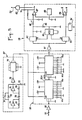
- a conventional transmitter 20 in frequency modulation provided with an antenna 21, and intended to receive by a line 11 low frequency electrical signals representing a radio program to be broadcast and coming from a microphone or a unit for reading recorded information such as a turntable 10 or a tape or cassette recorder.
- the radio program is simply transmitted in a conventional manner by the FM transmitter 20 and its antenna 21.
- digital signals coded on the program signals applied by line 11 are superimposed, before frequency modulation transmission, in a mixer 32, so that the FM transmitter then receives via line 33 a mixture of conventional low frequency signals and coded signals.
- the coded signals can be very easily formed from plain text messages using a conventional computer terminal 40 equipped with a keyboard and capable of delivering on a line 41 signals coded according to a preset code, by example in RTTY code according for example to an RS 232 format.
- the terminal 40 may include a conventional unit allowing storage and management of texts.
- the coded signals can also come directly from a memory or other recording medium.
- the coded signals can be formed from the reading of a bar code using an optical reading device.
- the coded signals can be constituted by coded signals which cannot be decoded after transmission by radio but which are already present in the recording medium read in the reading device 10 for the radio transmission by the transmitter 20.
- the signals from the reading device 10 can also be applied by the line 11 a to a decoder 12 suitable for decoding encoded discs, cassettes or magnetic tapes.
- the signals coming from the decoder 12 by the line 4 1 a which include a coded message can then be used to supply the coder 30 intended to receive the coded signals transmitted by the line 41.
- the encoder 30 essentially comprises a modulator 34 of the FSK type (frequency shift modulation) so as to transmit on line 31 coded signals characterized by two predetermined frequency levels.
- the FSK modulator 34 is designed in such a way that the frequency levels of the coded signals are situated between approximately 15 kHz and 18 kHz and that the level of the coded signals of line 31 is attenuated by 20 to 40 dB for take into account the level curve of the LF signals usually transmitted by line 11 (see Figure 6). In this way, after mixing in the mixer 32, with the LF signals present on line 11, the coded signals of line 31 do not affect the quality of the conventional radio broadcast and are not removed by the filters either. conventional frequency modulation transmitters or receivers.
- the introduction of the coded signals can be carried out directly in the FM transmitter 20, by the line 31 a dotted on the Figure 1, downstream of the stereophonic filters.
- the mixer 32 of FIG. 1 is naturally deleted and the line 33 transmits the same signals as the line 11.
- the reinjection of coded signals after the stereophonic filters of the FM transmitter makes it possible then to facilitate the separation of the signals encoded at reception, thanks to gain obtained in the frequency band of FSK modulated coded signals.
- FIG. 2 schematically shows the elements of the receiving assembly of a device according to the invention.
- These elements essentially comprise a standard frequency modulation receiver 120 with its antenna 121, a decoder 50 and a display unit 60 which may be a standard television receiver or a computer terminal provided with a peri-computer input.
- the signals applied to the decoder 50 can be taken from an audio socket by a line 51 or, preferably, by a line 51 a , in dotted lines in FIG. 2, before the de-emphasis circuits of the receiver 120, which makes it possible to have available '' a gain of the order of 10 to 15 dB in the frequency band containing the coded signals.
- the coded signals which in the decoder 50, are separated from the conventional radio message, are applied to the display unit 60 by a line 52 and can then appear in clear on the screen. At the same time, the listener can listen to the usual radio program.
- the decoder 50 can be integrated if necessary into the housing of the FM receiver 120.
- the display unit 60 is constituted by a computer terminal, it is also possible to send coded signals from control at the decoder 50 by the line 53 from the terminal 60, in order to adapt to different reception cases and control for example the programming of the quality factor or of the central frequency of the filter contained in the decoder.
- a recording unit constituted for example by a memory can be substituted or associated with the display unit 60 to record the coded signals coming from the demodulator 50.
- FIG. 3 shows the constituent elements of the decoder 50.
- a level adapter 55 receives via an input capacitor 54 the complex signals delivered on lines 51 or 51 a by the FM receiver 120, as previously indicated.
- the output of the level adapter 55 is connected to filter circuits 56 which are preferably programmable band-pass filters with capacitor switching associated with a clock 57.
- the programming of the filters can be carried out once and for all, at using keys, but can also be adapted by the user, if the unit 60 is constituted by a computer terminal.
- Level control elements 63, 64 are respectively disposed before and after the filter circuits 56.
- An FSK demodulator 58 with phase loop is placed at the output of the filters 56 and of the error correction circuits 59 sensitive to coded signals. error correction can optionally be placed at the output of the FSK demodulator 58.
- Adapters 61, 62 depending on the type of display unit 60 are interposed between the output of the decoder 50 and line 52 a , 52 respectively provided for leading to two display units 60 of different type.
- FIG. 4 shows a particular example of an FSK modulator which can be incorporated into the encoder 30 of FIG. 1.
- This modulator 34 is built around a standard basic circuit, for example the XR2206 circuit from the company EXAR - and has characteristics adaptable using external resistors and capacitors.
- the coded signals are applied to input 35 and the FSK modulated output signals having a sinusoidal shape are available on an output 36. Rectangular output signals are available on an output 37 for control purposes.
- the FSK modulator 34 can comprise a basic circuit with current switches 131, a frequency controlled oscillator (VCO) circuit 132 and a multiplier and setting circuit 133 in sinusoidal form.
- VCO frequency controlled oscillator
- the external components can then include resistors or potentiometers 141 to 144 and a frequency adjustment capacitor 145, resistors or potentiometers 151 to 153 and a capacitor 154 for adjusting the output signal level, as well as resistors or potentiometers 161, 162 for adjusting the shape and symmetry of the sinusoidal output signal, aiming to obtain minimum distortion.
- the ratio between the frequency excursion of the signals modulated by frequency shift expressed in herz and the speed of transmission of the coded information to be transmitted , expressed in baud is between approximately 85 and 120% and preferably close to 100%.
- the frequency offset caused by the FSK modulator is for example ⁇ 150Hz.
- FIG. 5 shows in more detail an exemplary embodiment of a decoder-demodulator circuit 50 with a clock 57 comprising a frequency reference element 70 mounted in parallel on a capacitor 71 and inverting logic gates 73, 74, 75 associated with resistors 77, 79, capacitors 72, 78 and an output circuit 76 constituted by a frequency divider (for example by 9) which makes it possible to deliver clock pulses of the order of 1MHz, for example at a frequency of 8MHz divided by 9.
- a frequency divider for example by 9
- the set 56 of filter circuits comprises first and second filters 56 a, 56 b for switching capacitors and can be constituted for example by the R5620 circuits of Reticon Corporation.
- the characteristics of the filters 56 a, 56b programmbles can be determined by switches, as shown in Figure 5 or, as indicated above, by control signals from the terminal 60.
- the filters 56 a, 56 b may be password-type -band or high pass.
- the demodulator 58 shown in FIG. 5 has a conventional configuration with an input preamplifier 81, a frequency-controlled circuit (VCO) 80, phase and quadrature detectors 83, a filter 84 for locking detection, filters loop, and data 85, 86, a latch condition detection comparator 88, an internal reference circuit 89 and a FSK comparator 87 delivering output signals corresponding to the demodulated transmitted coded signals.
- VCO frequency-controlled circuit
- FSK comparator 87 delivering output signals corresponding to the demodulated transmitted coded signals.
- the coded information to be transmitted is transmitted in a repeating loop.
- the coded message transmitted will advantageously include control characters, including an image erasure code, placed before each message phase, as well as an end of message signaling code.
- the transmitted coded message comprises non-displayable coded characters and the transmitted non-displayable coded characters are recorded by applying filtered and demodulated signals to a memory unit. This can help, for example, to facilitate the measurement of listening rates of radio stations identified by a specific code.
- the invention is particularly suitable for the use of the decoder-demodulator in combination with a personal computer terminal such as for example that known under the name ALCATEL 250.
- the control characters include a character ensuring the configuration of the personal terminal in roll mode.
Landscapes
- Engineering & Computer Science (AREA)
- Signal Processing (AREA)
- Digital Transmission Methods That Use Modulated Carrier Waves (AREA)
- Transmitters (AREA)
- Circuits Of Receivers In General (AREA)
- Reduction Or Emphasis Of Bandwidth Of Signals (AREA)
Claims (11)
- Verfahren und Einrichtung zur Übertragung kodierter Informationen über einen Funkkanal durch Überlagerung auf eine herkömmliche FM-Übertragung, wobei man in einem vorbestimmten Frequenzband oberhalb von 15 kHz, die zu übertragenden kodierten Informationen moduliert, um modulierte kodierte Signal zu schaffen, mischt diese kodierten, modulierten Signale mit niederfrequenten Signalen eines üblichen Programmes bevor die FM-Übertragung ausgestrahlt wird, filtert die von einem FM-Empfänger abgegebenen Signale, um die kodierten modulierten Signale zu isolieren, demoduliert die kodierten, modulierten, filtrierten Signale und gibt die übertragenen kodierten Informationen aus oder speichert sie durch Anlegen der kodierten, gefilterten und demodulierten Signale auf eine Anzeigeeinheit oder eine Speichereinheit, dadurch gekennzeichnet, daßa) man die kodierten, abzusenden Informationen durch Frequenzverschiebung in einem Frequenzbereich zwischen etwa 15 und 18 kHz moduliert,b) man die kodierten, modulierten Signale durch Frequenzverschiebung mit einer Abschwächung von 20 bis 40 dB, bezüglich des maximalen Niveaus der Übertragung mit den genannten niederfrequenten Signalen eines üblichen Programmes mischt,c) das Verhältnis der Frequenzabweichung der kodierten, modulierten Signale durch Frequenzverschiebung, ausgedrückt in Hz und die Übertragungsgeschwindigkeit der zu übertragenden kodierten Informationen, ausgedrückt in bauds, wird zwischen etwa 85 und 120 % und vorzugsweise nahe 100 % gehalten,d) die Eingangssignale auf einem Rechner-Terminal gefiltert und demoduliert werden, mit dessen Hilfe man die Kennzeichen des Filterns kontrollieren und steuern kann.
- Verfahren nach Anspruch 1, dadurch gekennzeichnet, daß man die durch Frequenzverschiebung modulierten Signale stromabwärts der Stereofilter des FM-Senders aufbringt, um die Überlagerung der modulierten Signale und der Signale eines herkömmlichen Programmes beim Senden zu erreichen.
- Verfahren nach Anspruch 1 oder 2, dadurch gekennzeichnet, daß man die zu filternden Eingangssignale stromaufwärts der Entzerrungskreise des FM-Standardsempfängers abnimmt.
- Verfahren nach einem der Ansprüche 1 bis 3, dadurch gekennzeichnet, daß die durchzugebenden kodierten Informationen in einer Wiederholungsschleife übermittelt werden.
- Verfahren nach einem der Ansprüche 1 bis 4, dadurch gekennzeichnet, daß man die Ausgabe der übertragenen kodierten Informationen mittels der filtrierten und demodulierten Signale auf eine Anzeigeeinheit eines Rechner-Terminals oder einem Fernsehempfänger durchführt und dadurch, daß die übertragene kodierte Nachricht Steuerzeichen umfaßt, die einen Bildlöschcode vor jeder Nachrichtenphase plazieren.
- Verfahren nach einem der Ansprüche 1 bis 5, dadurch gekennzeichnet, daß die übertragene kodierte Nachricht kodierte nicht anzeigbare Elemente enthält und dadurch, daß man die Speicherung der nicht anzeigbaren kodierten Elemente durch Anlegen der demodulierten gefilterten Signale an eine Speichereinheit speichert.
- Vorrichtung zur Übertragung kodierter Informationen über einen Funkkanal durch Überlagerung auf eine herkömmliche FM-Übertragung, dadurch gekennzeichnet, daß sie eine Eingangseinheit (40) aufweist, um die zu übertragenden kodierten Informationen aufzunehmen, einen Kodiermodulator (30) FSK, um durch Frequenzverschiebung in einen Frequenzbereich zwischen etwa 15 bis 18 kHz, die zu übertragenden kodierenden Informationen zu modulieren, einem Mischschaltkreis (32), um mit einer Abschwächung von 20 bis 40 dB, die durch Frequenzverschiebung modulierten Signale einem niedrigfrequenten Signal eines üblichen Programmes zu überlagern, bevor es einem FM-Sender (20) zugeleitet wird, einen Dekoder (50), der Filterkreise (56) aufweist und einen FSK-Demodulator (50), um die kodierten Informationen, der von einem FM-Standardempfänger (120) abgegebenen Signale zu trennen und einer Anzeige- oder Speichereinheit (60), die aus einem Rechner-Terminal besteht, um die übertragenen kodierten Informationen, die gefilter und demoduliert sind, anzuzeigen oder zu speichern, und dadurch, daß die Filterkreise (56) durch Kondensatorschaltungen programmierbare Bandpaßfilter aufweisen, die mit einem Taktgeber (57) verbunden sind und dadurch, daß eine Verbindung (53) zwischen dem Rechner-Terminal (60), das die Anzeige der kodiert übertragenen Informationen sichert und den programmierbaren Filtern (56) des Dekoders (50) vorgesehen ist, um die Kodierungen für die programmierbare Steuerung zu übermitteln.
- Vorrichtung nach Anspruch 7, dadurch gekennzeichnet, daß der Mischkreis (32) stromabwärts der Stereofilter des FM-Senders (20) angeordnet ist.
- Vorrichtung nach einem der Ansprüche 7 und 8, dadurch gekenneichnet, daß die auf den Dekoder (50) gelegten Signale stromauswärts der Entzerrerkreise des Standard-FM-Empfängers (120) abgenommen werden.
- Vorrichtung nach einem der Ansprüche 7 bis 9, dadurch gekennzeichnet, daß der Dekoder (50) weiters einen Niveau-Regler (55) aufweist, der am Eingang angeordnet ist und zwei Niveau-Regler (63, 64), die zu beiden Seiten des Filterkreises angeordnet sind.
- Vorrichtung nach einem der Ansprüche 7 bis 10, dadurch gekennzeichnet, daß die Frequenzverschiebung im Kodier-Modulator (30) die Größenordnung von 300 Hz hat und daß eine Übertragung der kodierten Informationen in der Größenordnung von 300 bauds erfolgt.
Priority Applications (1)
| Application Number | Priority Date | Filing Date | Title |
|---|---|---|---|
| AT85401547T ATE64048T1 (de) | 1984-07-30 | 1985-07-29 | Verfahren und einrichtung zur uebertragung kodierter informationen ueber einen funkkanal durch ueberlagerung auf eine herkoemmliche fm¨bertragung. |
Applications Claiming Priority (2)
| Application Number | Priority Date | Filing Date | Title |
|---|---|---|---|
| FR8412092 | 1984-07-30 | ||
| FR8412092A FR2568432B1 (fr) | 1984-07-30 | 1984-07-30 | Procede et dispositif de transmission d'informations codees par voie hertzienne en superposition a une emission traditionnelle en modulation de frequence |
Publications (2)
| Publication Number | Publication Date |
|---|---|
| EP0172095A1 EP0172095A1 (de) | 1986-02-19 |
| EP0172095B1 true EP0172095B1 (de) | 1991-05-29 |
Family
ID=9306637
Family Applications (1)
| Application Number | Title | Priority Date | Filing Date |
|---|---|---|---|
| EP85401547A Expired - Lifetime EP0172095B1 (de) | 1984-07-30 | 1985-07-29 | Verfahren und Einrichtung zur Übertragung kodierter Informationen über einen Funkkanal durch Überlagerung auf eine herkömmliche FM-Übertragung |
Country Status (6)
| Country | Link |
|---|---|
| EP (1) | EP0172095B1 (de) |
| JP (1) | JPS6199446A (de) |
| AT (1) | ATE64048T1 (de) |
| CA (1) | CA1253920A (de) |
| DE (1) | DE3582979D1 (de) |
| FR (1) | FR2568432B1 (de) |
Cited By (3)
| Publication number | Priority date | Publication date | Assignee | Title |
|---|---|---|---|---|
| DE3512297A1 (de) * | 1985-04-04 | 1986-10-16 | Grundig Emv | Einrichtung zum empfang von zusatzinformationen im hoerrundfunk |
| US8248528B2 (en) | 2001-12-24 | 2012-08-21 | Intrasonics S.A.R.L. | Captioning system |
| US8560913B2 (en) | 2008-05-29 | 2013-10-15 | Intrasonics S.A.R.L. | Data embedding system |
Families Citing this family (13)
| Publication number | Priority date | Publication date | Assignee | Title |
|---|---|---|---|---|
| FR2619662A1 (fr) * | 1987-08-19 | 1989-02-24 | Bernard Alain | Procede de transmission d'informations relatives aux courses et recepteur pour la mise en oeuvre de ce procede |
| WO1989007374A1 (en) * | 1988-02-08 | 1989-08-10 | Robert John Suffern | Apparatus for transmitting information |
| FR2630604A1 (fr) * | 1988-04-22 | 1989-10-27 | Marinier Denis | Procede et dispositif de communication, par sous-porteuses integrees dans un signal analogique ou numerique |
| DE58908783D1 (de) * | 1989-10-16 | 1995-01-26 | Falter & Funk Gmbh Co | Vorrichtung zur Übertragung von Audioinformationen und/oder digitalen Informationen. |
| ES2048043B1 (es) * | 1991-08-14 | 1995-12-16 | Baranoff Rossine Dimitri | Proceso y dispositivo para la radio transmision de datos codificados superpuestos sobre una radiodifusion tradicional de frecuencia modulada |
| GR910100504A (el) * | 1991-12-18 | 1993-08-31 | Baranoff Rossine Dimitri | Μεθοδος και διαταξh για ραδιομεταδοση κωδικοποιημενων δεδομeνων τοποθετουμενων επι παραδοσιακου πομπου διαμορφωμενης συχνοτητος. |
| DE4142332A1 (de) * | 1991-12-20 | 1993-07-01 | Bosch Siemens Hausgeraete | Rundfunkempfangsgeraet zum bestimmungsgemaessen empfang von hoerfunkprogrammen |
| US5630203A (en) * | 1993-01-12 | 1997-05-13 | Weinblatt; Lee S. | Technique for surveying a radio or a television audience |
| KR0123755B1 (ko) * | 1993-08-19 | 1997-12-01 | 김광호 | 음성신호 송수신시스템 |
| GB9700854D0 (en) | 1997-01-16 | 1997-03-05 | Scient Generics Ltd | Sub-audible acoustic data transmission mechanism |
| GB9917985D0 (en) | 1999-07-30 | 1999-09-29 | Scient Generics Ltd | Acoustic communication system |
| AU2211102A (en) | 2000-11-30 | 2002-06-11 | Scient Generics Ltd | Acoustic communication system |
| EP2288121A3 (de) | 2000-11-30 | 2011-06-22 | Intrasonics S.A.R.L. | Telekommunikationsvorrichtung mit Audioübertragung-interaktivem Betrieb |
Family Cites Families (1)
| Publication number | Priority date | Publication date | Assignee | Title |
|---|---|---|---|---|
| EP0066076B1 (de) * | 1981-06-02 | 1986-02-19 | Texas Instruments Incorporated | Integriertes Modem für frequenzangetastete Signale |
-
1984
- 1984-07-30 FR FR8412092A patent/FR2568432B1/fr not_active Expired - Lifetime
-
1985
- 1985-07-27 JP JP60166615A patent/JPS6199446A/ja active Pending
- 1985-07-29 AT AT85401547T patent/ATE64048T1/de not_active IP Right Cessation
- 1985-07-29 EP EP85401547A patent/EP0172095B1/de not_active Expired - Lifetime
- 1985-07-29 CA CA000487662A patent/CA1253920A/en not_active Expired
- 1985-07-29 DE DE8585401547T patent/DE3582979D1/de not_active Expired - Lifetime
Cited By (3)
| Publication number | Priority date | Publication date | Assignee | Title |
|---|---|---|---|---|
| DE3512297A1 (de) * | 1985-04-04 | 1986-10-16 | Grundig Emv | Einrichtung zum empfang von zusatzinformationen im hoerrundfunk |
| US8248528B2 (en) | 2001-12-24 | 2012-08-21 | Intrasonics S.A.R.L. | Captioning system |
| US8560913B2 (en) | 2008-05-29 | 2013-10-15 | Intrasonics S.A.R.L. | Data embedding system |
Also Published As
| Publication number | Publication date |
|---|---|
| EP0172095A1 (de) | 1986-02-19 |
| CA1253920A (en) | 1989-05-09 |
| ATE64048T1 (de) | 1991-06-15 |
| JPS6199446A (ja) | 1986-05-17 |
| FR2568432A1 (fr) | 1986-01-31 |
| DE3582979D1 (de) | 1991-07-04 |
| FR2568432B1 (fr) | 1990-06-29 |
Similar Documents
| Publication | Publication Date | Title |
|---|---|---|
| EP0172095A1 (de) | Verfahren und Einrichtung zur Übertragung kodierter Informationen über einen Funkkanal durch Überlagerung auf eine herkömmliche FM-Übertragung | |
| US4811357A (en) | Secondary channel for digital modems using spread spectrum subliminal induced modulation | |
| US5128933A (en) | Process and device for the radio transmission of coded data superimposed on a traditional frequency-modulated broadcast | |
| US4225967A (en) | Broadcast acknowledgement method and system | |
| EP0545783A1 (de) | Halbduplex-Modem für GSM-Mobilfunknetz | |
| FR2494018A1 (fr) | Dispositif pour enregistrer et restituer des signaux sur des supports d'enregistrement de haute densite | |
| EP0702481A1 (de) | Detektor für Trägerverlust in einem Faksimile-Modem | |
| EP0827310A2 (de) | Infrarotübertragung von digitalen Audiosignalen | |
| US5590161A (en) | Apparatus for synchronizing digital data without using overhead frame bits by using deliberately introduced errors for indicating superframe synchronization of audio signals | |
| US2709254A (en) | Subscription radio broadcasting system and equipment therefor | |
| JPS59115640A (ja) | 秘話信号伝送方式 | |
| EP0273815B1 (de) | Verfahren und Einrichtung mit einstellbarem Schutzniveau für Modulation und Demodulation mit verschiedenen Zuständen | |
| US3824470A (en) | Communications system and method for transmitting over a limited bandwidth transmission link | |
| Kinoshita et al. | Evaluation of 16 kbit/s digital voice transmission for mobile radio | |
| EP0085453A1 (de) | Elektronisches System zur geheimen Übertragung von Audiosignalen | |
| US3699447A (en) | Wideband frequency modulation communications system | |
| JPS6034859B2 (ja) | 信号伝送方式 | |
| JPH0276486A (ja) | 映像信号の光伝送システム | |
| Papadopoulos et al. | Simultaneous broadcasting of analog fm and digital audio signals by means of precanceling techniques | |
| EP0731588A1 (de) | Phasenmodulation mit mehrfacher Auflösung, für Mehrträgersysteme | |
| US20100136921A1 (en) | Interface unit for display of alphanumeric data | |
| JPH0436800A (ja) | 録音再生装置 | |
| Law | Pulse Code Modulation Telemetry | |
| JPH0879321A (ja) | デイジタル信号伝送装置、デイジタル信号伝送方法及びデイジタル信号送受信装置 | |
| JP3009025U (ja) | 送信装置 |
Legal Events
| Date | Code | Title | Description |
|---|---|---|---|
| PUAI | Public reference made under article 153(3) epc to a published international application that has entered the european phase |
Free format text: ORIGINAL CODE: 0009012 |
|
| AK | Designated contracting states |
Designated state(s): AT BE CH DE GB IT LI LU NL SE |
|
| 17P | Request for examination filed |
Effective date: 19860721 |
|
| 17Q | First examination report despatched |
Effective date: 19881010 |
|
| GRAA | (expected) grant |
Free format text: ORIGINAL CODE: 0009210 |
|
| AK | Designated contracting states |
Kind code of ref document: B1 Designated state(s): AT BE CH DE GB IT LI LU NL SE |
|
| REF | Corresponds to: |
Ref document number: 64048 Country of ref document: AT Date of ref document: 19910615 Kind code of ref document: T |
|
| PGFP | Annual fee paid to national office [announced via postgrant information from national office to epo] |
Ref country code: AT Payment date: 19910702 Year of fee payment: 7 |
|
| REF | Corresponds to: |
Ref document number: 3582979 Country of ref document: DE Date of ref document: 19910704 |
|
| PGFP | Annual fee paid to national office [announced via postgrant information from national office to epo] |
Ref country code: CH Payment date: 19910708 Year of fee payment: 7 |
|
| GBT | Gb: translation of ep patent filed (gb section 77(6)(a)/1977) | ||
| PGFP | Annual fee paid to national office [announced via postgrant information from national office to epo] |
Ref country code: LU Payment date: 19910717 Year of fee payment: 7 |
|
| PGFP | Annual fee paid to national office [announced via postgrant information from national office to epo] |
Ref country code: SE Payment date: 19910723 Year of fee payment: 7 Ref country code: GB Payment date: 19910723 Year of fee payment: 7 |
|
| PGFP | Annual fee paid to national office [announced via postgrant information from national office to epo] |
Ref country code: NL Payment date: 19910731 Year of fee payment: 7 |
|
| PGFP | Annual fee paid to national office [announced via postgrant information from national office to epo] |
Ref country code: BE Payment date: 19910809 Year of fee payment: 7 |
|
| ITF | It: translation for a ep patent filed | ||
| EPTA | Lu: last paid annual fee | ||
| PLBE | No opposition filed within time limit |
Free format text: ORIGINAL CODE: 0009261 |
|
| STAA | Information on the status of an ep patent application or granted ep patent |
Free format text: STATUS: NO OPPOSITION FILED WITHIN TIME LIMIT |
|
| 26N | No opposition filed | ||
| PG25 | Lapsed in a contracting state [announced via postgrant information from national office to epo] |
Ref country code: LU Free format text: LAPSE BECAUSE OF NON-PAYMENT OF DUE FEES Effective date: 19920729 Ref country code: GB Effective date: 19920729 Ref country code: AT Effective date: 19920729 |
|
| PG25 | Lapsed in a contracting state [announced via postgrant information from national office to epo] |
Ref country code: SE Effective date: 19920730 |
|
| PG25 | Lapsed in a contracting state [announced via postgrant information from national office to epo] |
Ref country code: LI Effective date: 19920731 Ref country code: CH Effective date: 19920731 Ref country code: BE Effective date: 19920731 |
|
| BERE | Be: lapsed |
Owner name: BARANOFF-ROSSINE DIMITRI Effective date: 19920731 |
|
| PG25 | Lapsed in a contracting state [announced via postgrant information from national office to epo] |
Ref country code: NL Effective date: 19930201 |
|
| PGFP | Annual fee paid to national office [announced via postgrant information from national office to epo] |
Ref country code: DE Payment date: 19930216 Year of fee payment: 8 |
|
| NLV4 | Nl: lapsed or anulled due to non-payment of the annual fee | ||
| GBPC | Gb: european patent ceased through non-payment of renewal fee |
Effective date: 19920729 |
|
| REG | Reference to a national code |
Ref country code: CH Ref legal event code: PL |
|
| PG25 | Lapsed in a contracting state [announced via postgrant information from national office to epo] |
Ref country code: DE Effective date: 19940401 |
|
| EUG | Se: european patent has lapsed |
Ref document number: 85401547.6 Effective date: 19930204 |