EP0172094B1 - Operational system for a plurality of closely located radars - Google Patents
Operational system for a plurality of closely located radars Download PDFInfo
- Publication number
- EP0172094B1 EP0172094B1 EP85401544A EP85401544A EP0172094B1 EP 0172094 B1 EP0172094 B1 EP 0172094B1 EP 85401544 A EP85401544 A EP 85401544A EP 85401544 A EP85401544 A EP 85401544A EP 0172094 B1 EP0172094 B1 EP 0172094B1
- Authority
- EP
- European Patent Office
- Prior art keywords
- radars
- phase
- radar
- closely located
- operational system
- Prior art date
- Legal status (The legal status is an assumption and is not a legal conclusion. Google has not performed a legal analysis and makes no representation as to the accuracy of the status listed.)
- Expired
Links
Images


Classifications
-
- G—PHYSICS
- G01—MEASURING; TESTING
- G01S—RADIO DIRECTION-FINDING; RADIO NAVIGATION; DETERMINING DISTANCE OR VELOCITY BY USE OF RADIO WAVES; LOCATING OR PRESENCE-DETECTING BY USE OF THE REFLECTION OR RERADIATION OF RADIO WAVES; ANALOGOUS ARRANGEMENTS USING OTHER WAVES
- G01S13/00—Systems using the reflection or reradiation of radio waves, e.g. radar systems; Analogous systems using reflection or reradiation of waves whose nature or wavelength is irrelevant or unspecified
- G01S13/87—Combinations of radar systems, e.g. primary radar and secondary radar
Definitions
- This patent application relates to a particular operating system of very long range radar transceivers.
- the invention can be extended to other technical sectors for which it is sought to optimize the operation of multiple transceivers by obtaining certain phase relationships both between the transmission signals and those of reception.
- the invention therefore relates to an operating system of N neighboring radars, each radar comprising transmission means, reception means and antenna means connected to the transmission and reception means by a duplexer characterized in that the transmission means are arranged to transmit signals of the same frequency, each having its own phase reference and the relationships between these phase references being arbitrary, along beams, with parallel axes, merged at great distance inside from a common area, the distance separating the antennas from neighboring radars, taken two by two, being clearly greater than the largest of the antenna openings of the radars considered, so that inside the common area, it there are directions in which the signals transmitted by all the radars are substantially in phase and in that the reception means comprise means for phasing the received signals so as to carry out vector addition e of these signals.
- phase of the emission signal, of the reception signals and of a test signal; this, in a reference plane P; defined for each speed camera i; this reference plane is preferably placed in the vicinity of the antenna side duplexer, in a similar manner for each radar.
- the phase reference can be different for each radar, but wing is imperatively at the same frequency for all radars, this frequency being the common emission frequency; the deviations from one reference to the other can thus only be a constant phase shift (which should be taken into account in the calculation of the phase correction A 0 as will be seen later).
- the reference is in fact a fictitious sinusoid S at the emission frequency f, which would result from the beat between a local oscillation in microwave f H and a local oscillation in intermediate frequency f i ; this sinusoid S; is fictitious because according to the methods well known to those skilled in the art, a phase measurement is preferably made at the output of an amplifier at intermediate frequency after a frequency change using the above-mentioned local oscillation at the frequency f H. Under these conditions, the result of the measurement gives the phase of the signal only to a constant K ij which depends in particular on the completion of the frequency change and of the amplifier at intermediate frequency. However, the influence of this constant disappears when measuring phase differences, at the output of the devices which are symmetrical, the phase difference measured at intermediate frequency corresponding exactly to the phase difference of the signals themselves.
- Two neighboring bright bands have asymptotic directions defined by half-angle cones at the vertex ⁇ 1 and ⁇ 2 such that:
- the interfringe becomes very large because of the small value of sin 0; for these directions, the interfringe is greater than the width of the beam common to the 2 radars, it may be that a phase combination 0.0 or 0.1 (as defined below) corresponds to a dark fringe but in this the other combination corresponds to a bright fringe. There are also cases (dependent on the initial phase shift 1 , 2 ) for which the combinations 0.0 and 0.1 both correspond to intermediate values for the intensity of the fringes.
- phase relationships between the radar transmitters in order to shift the system of interference fringes between the radars.
- the purpose of this is to make the shiny fringes scan in steps the directions of the space located inside the beam common to the radars.
- This phase modification is made either from impulse to impulse or from burst to burst when the radars perform a signal processing which uses coherence techniques (coherent integration, Doppler filtering, etc.).
- the simplest case is that where there are only 2 radars; we can then modify the phase relationship between the 2 transmitters only once, going from ⁇ to ⁇ + ⁇ ; this allows the network of bright fringes and the network of dark fringes to be permuted; in this way, a coarse scan of the directions of space located inside the beam common to the two radars is created. If we want to improve the smoothness of the scan, we will go from ⁇ to ⁇ + 2 ⁇ 3 then to ⁇ + 4 ⁇ 3. But this will require 3 successive transmissions (or 3 bursts).
- the coarse scanning of the directions of space located inside the beam common to the 3 radars corresponds to 4 successive transmissions (or 4 bursts) defined as follows: either ⁇ 12 and ⁇ 13 the respective phase shifts between the transmitters 1 and 2, then 1 and 3 during the first pulse (or the first burst).
- the first column on the left corresponds to radar n ° 1; the second column corresponds to radar 2; the third column on radar 3.
- the number 0 placed in the 2nd column indicates that the phase relationship between the first 2 radars is kept constant, its (any) value is called ⁇ 12 ; the number 1 placed in the 2nd column indicates that the previous value goes from ⁇ 12 to ⁇ 12 + n.
- the third column indicates the phase difference between radar no. 3 and radar 1; the number 0 indicates that the phase difference between the 2 radars is kept constant at its initial value (any) ⁇ 13 ; the number 1 indicates that the phase shift goes from the value ⁇ 13 to ⁇ 13 + n.
- the presence of a 0 indicates that the phase of the i-th radar is kept constant (equal to any ⁇ 1, i ), the presence of a 1 indicates that ⁇ 1 , i is replaced by ⁇ 1, i + 2 ⁇ 3 the presence of a 2 indicates that ⁇ 1, i is replaced by ⁇ 1, i + 4 ⁇ 3.
- three radars R1, R2, R3 are provided which, instead of being aligned, are placed at the vertices of a triangle.
- this triangle can be equilateral.
- the search and tracking volume is then preferably centered on the normal to the plane of the triangle which passes through the orthocenter of the triangle.
- the interference system between R, and R 2 is a hyperboloid network of revolution around the line R I R 2
- the interference system between R, and R 3 is a hyperboloid network of revolution around the line R l R 3 .
- the arrangement in the preceding triangle is combined with aligned arrangements.
- five radars R1 to R5 are arranged at the vertices of two equilateral triangles having in common an angia at the vertex, the angle R1 for example.
- the radars R1, R3, R5 are therefore aligned as well as the radars R1, R2 and R4.
- the reception sets are supposed to have two by two equal transmission times and equal phase shifts between their inputs and their corresponding outputs as defined for the comparison of radars two by two.
- the measurement of the phase difference between the transmissions can be made according to Figure 5 where there are two radars 1 and 2 each comprising a transmitter (E1, E2), a receiver (REC1, REC2), a duplexer (D1, D2) connecting the transmitter and the receiver to an antenna (A1, A2).
- Each radar also has, according to the invention, in the reception chain, a phase shifter (DEPH1, DEPH2) receiving the preamplified signal from the amplifier (REC1, REC2) and transmitting it to the amplifier (REC'1, REC '2) after introduction of a controllable phase shift.
- the two radars are coupled by two directional couplers (CP1, CP2) to a single G waveguide.
- a first phase shift measurement system S1 with two inputs e1 and e'1 coupled to the waveguide G by two directional couplers CM1 and CM'1 suitably oriented.
- a second phase shift measurement system S2 has two inputs e2 and e'2 coupled, by directional couplers (CM2 and CM'2) suitably oriented, to the waveguide G.
- CM2 and CM'2 directional couplers
- the electrical length of the track connecting the directional couplers CP1 and CM1 is equal to that of the track connecting the directional couplers CP2 and CM2.
- the CM1-CM'1 link is identical to the CM2-CM'2 link.
- the electrical length of the channel connecting the directional coupler CP1 to the output of the receiver REC'1 is equal to that of the channel connecting the coupler CP2 to the output of the receiver REC'2 and this when the two phase shifters DEPH 1 and DEPH 2 are in the zero phase shift position.
- phase measurement systems S1, S2 make it possible to measure the phase differences of the signals on transmission from the two radars 1 and 2.
- the results of these measurements are transmitted to a difference and control circuit UC.
- These circuits make it possible to obtain the value of the phase difference 02 - 01 of the signals on transmission. More precisely, they make it possible to obtain the value 2 (0 2 - 0 1 ).
- the UC circuits control the DEPH1 and DEPH2 phase shifters. A differential phase shift is thus introduced as will be described below.
- the emission signal from each of the radars is sent to the other via a single guide G where the two emission signals propagate in opposite directions.
- These transmission signals are taken from radars 1 and 2 by the respective directional couplers CP1 and CP2 placed on the common channel for the transmission and reception of each radar.
- CP1 and CP2 a reference plane PR11 and PR21 respectively, these two reference planes being situated similarly inside the couplers. These two plans define the entrance to the reception channels of each speed camera.
- the system S1 measures the phase shift M1 between the signal of the local emission of the radar 1 and the signal of the emission of the radar 2 received via the guide G.
- the measurement system S2 measures the phase shift M2 between the signal from the local radar 2 emission and the signal from the radar 1 emission received via the guide G.
- the two measurement systems S1 and S2 take the signals subjected to the measurements via the respective couplers CM1, CM'1 and CM2, CM'2.
- the coupler CM1 supplies the local signal from radar 1 to input e1 of the measurement system S1.
- the coupler CM'1 supplies the input signal from transmitted radar 2 to input e'1 of the measurement system S1. by the guide G.
- the coupler CM2 supplies to the input e2 of the system S2, the local signal from the radar 2 and the coupler CM'2 supplies to the input e'2. the radar 1 emission signal transmitted by guide G.
- the two sets of couplers CP1, CM1, CM'1 on the one hand and CP2, CM2 and CM'2 on the other hand are identical as well as their internal connections. All directional couplers are fitted with a suitable load in the fourth channel in accordance with good practice.
- ⁇ ' 2 being the phase of the radar signal 2 received by the guide G.
- 0 1 and 0 2 represent, to the same constant constant, the emission phases respectively in the reference planes PR1 and PR2.
- a y representing the phase shift due to the waveguide G.
- the phase difference between the emissions from radars 1 and 2 in the reference planes PR1 and PR2 has been measured without having to know the length of the guide G.
- the radar whose emission is in phase advance will receive a signal in phase delay. To phase the 2 signals received by radars 1 and 2, it is therefore necessary to give a phase advance to the receiver corresponding to the transmission in phase advance.
- FIG. 5 represents the phase shifters DEPH1 and DEPH2 inserted between two receivers REC1, REC'1 for one of the phase shifters and REC2, REC'2 for the other phase shifter.
- these pairs of receivers REC1 - REC'1 and REC2 - REC'2 each form a single organ, a phase shifter (DEPH1, DEPH2) being placed inside each organ.
- phase shifters make it possible to compensate for the transmission phase shift, measured as described above, by a phase shift at reception.
- a difference calculation and control circuit UC makes it possible as a function of the measurement results M1 and M2 carried out by the measurement systems S1 and S2 to effect the difference M1 and M2 and to control the phase shifters DEPH1 and DEPH2 accordingly.
- the phase shift measurement system according to the invention may include a number n of radars.
- FIG. 6 represents a system with four radars.
- the measurement of the phase shifts on transmission is made by separate comparisons which all take radar 1 as a reference and use guides G2, G3, G4 respectively to propagate the signals to be compared in both directions.
- the coupling of G2, G3, G4 is made respectively to radar 1 by the couplers CP 1.2, CP 1.3 and CP 1.4.
- the respective couplings to radars 2, 3 and 4 are made by couplers CP2, CP3 and CP4.
- the homologous paths of a pair of radars are provided with equal lengths.
- each waveguide G2, G3, G4 are coupled two phase-shift measurement systems similar to the systems S1 and S2 of FIG. 5.
- phase shift measurement system S 1.3 by couplers CM 1.3 and CM '1.3 and, on the other hand, a phase shift measurement system S3 by CM3 and CM'3 couplers.
- the two phase-shift measurement systems associated with the same waveguide supply their measurement results to a difference and control circuit not shown in FIG. 6 and make it possible to control the phase shifters of the radars associated with this waveguide.
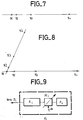
- FIG. 9 indicates the way of introducing the phase shifts ⁇ or and 4f into the transmitters E2, E3, ... etc. with respect to the transmitter E1.
- the transmitters are generally terminated by a power amplifier tube A so that it is preferable to introduce the above phase shifts at low level at the input of the power amplifier by a controlled phase shift DE at the output of the pilot Pi.
- each Pi pilot has its own frequency reference (for example, an atomic clock) such that its high stability prevents any frequency sliding during the duration of the transmissions or bursts which must be made at the same frequency c that is to say during the 2P- 1 or 3 pl successive transmissions or gusts which ensure the scanning in steps of the space inside the beam common to the radars.
- frequency reference for example, an atomic clock
Description
Cette demande de brevet concerne un système d'exploitation particulier d'émetteurs-recepteurs radars à très grande portée. L'invention peut être étendue à d'autres secteurs techniques pour lesquels on cherche à optimiser l'exploitation d'émetteurs-récepteurs multiples par l'obtention de certaines relations de phase tant entre les signaux d'émission que ceux de réception.This patent application relates to a particular operating system of very long range radar transceivers. The invention can be extended to other technical sectors for which it is sought to optimize the operation of multiple transceivers by obtaining certain phase relationships both between the transmission signals and those of reception.
Jusqu'à maintenant, les performances exigées des systèmes radars pouvaient être satisfaites par l'utilisation d'un seul radar. Cependant, l'amélioration des systèmes radars a été suivie rapidement par une augmentation de puissance des systèmes de brouillage et de leur efficacité. De plus, il s'avère nécessaire de détecter des cibles de plus en plus éloignées et de très faible surface équivalente. C'est pourquoi, on a été amene à concevoir un système radar plus performant mettant en oeuvre, non pas seulement un radar, mais plusieurs radars.Until now, the performance requirements of radar systems could be met by the use of a single radar. However, the improvement in radar systems was quickly followed by an increase in the power of jamming systems and their efficiency. In addition, it is necessary to detect targets that are increasingly distant and of very small equivalent area. This is why, we have been led to design a more efficient radar system using not only one radar, but several radars.
Ce système prenant pour base connue le document "INTERNATIONAL CONFERENCE RADAR - 82", 18 - 20 octobre 1982, pages 169 - 173.This system taking as known base the document "INTERNATIONAL CONFERENCE RADAR - 82", October 18 - 20, 1982, pages 169 - 173.
L'invention concerne donc un système d'exploitation de N radars voisins, chaque radar comportant des moyens d'émission, des moyens de réception et des moyens d'antenne reliés aux moyens d'émission et de réception par un duplexeur caractérisé en ce que les moyens d'émission sont agencés pour émettre des signaux de même frequence, ayant chacun une référence de phase propre et les relations entre ces références de phase étant quelconques, suivant des faisceaux, d'axes parallèles, confondus à grande distance à l'intérieur d'une zone commune, la distance séparant les antennes des radars voisins, pris deux à deux, étant nettement supérieure à la plus grande des ouvertures d'antennes des radars considérés, de manière qu'à l'intérieur de la zone commune, il existe des directions selon lesquelles les signaux émis par tous les radars sont sensiblement en phase et en ce que les moyens de réception comportent des moyens de mise en phase des signaux reçus de manière à réaliser d'addition vectorielle de ces signaux.The invention therefore relates to an operating system of N neighboring radars, each radar comprising transmission means, reception means and antenna means connected to the transmission and reception means by a duplexer characterized in that the transmission means are arranged to transmit signals of the same frequency, each having its own phase reference and the relationships between these phase references being arbitrary, along beams, with parallel axes, merged at great distance inside from a common area, the distance separating the antennas from neighboring radars, taken two by two, being clearly greater than the largest of the antenna openings of the radars considered, so that inside the common area, it there are directions in which the signals transmitted by all the radars are substantially in phase and in that the reception means comprise means for phasing the received signals so as to carry out vector addition e of these signals.
L'invention sera mieux comprise et diverses autres caractéristiques apparaîtront à l'aide de la description qui suit, faite en se référant aux figures annexées parmi lesquelles:
- - la figure 1 consiste en une figure explicative du système de l'invention;
- - la figure 2 illustre un exemple de disposition de trois radars selon les trois sommets d'un triangle;
- - les figures 3 et 4 illustrent des exemples de dispositions de cinq radars selon les sommets de deux triangles;
- - les figures 5 et 6 représentent des exemples de réalisation permettant de mettre en oeuvre le système de l'invention;
- - les figures 7 et 8 illustrent des variantes de dispositions radars;
- - la figure 9 représente un exemple de réalisation d'un circuit de déphasage.
- - Figure 1 consists of an explanatory figure of the system of the invention;
- - Figure 2 illustrates an example of arrangement of three radars according to the three vertices of a triangle;
- - Figures 3 and 4 illustrate examples of arrangements of five radars according to the vertices of two triangles;
- - Figures 5 and 6 show exemplary embodiments for implementing the system of the invention;
- - Figures 7 and 8 illustrate variants of radar arrangements;
- - Figure 9 shows an embodiment of a phase shift circuit.
Selon l'invention, on dispose plusieurs radars de telle façon que:
- - Dans certaines directions, les champs émis à la même fréquence par les p radars sont sensiblement en phase, ces directions étant comprises dans l'angle solide commun aux faisceaux-radars orientés parallèlement. Ceci pourra être obtenu par un choix judicieux de l'emplacement approximatif des radars, sans aucune contrainte sur les phases d'émission. On réalise ainsi un système complexe de franges d'interférence à l'émission dont une au moins a pratiquement la brillance maximale possible; la direction du ou des maximums de brillance ne sont d'ailleurs pas nécessairement connue.
- - On fait alors à la réception, l'addition vectorielle des champs diffractés par une cible avec des relations de phase telles que le système de franges d'interférences à la réception coïncide pratiquement avec celui existant à l'émission. Une cible fortement éclairée à l'émission renvoyant alors un écho qui est reçu avec la sensibilité maximale.
- - De plus, on modifie un nombre de fois suffisant mais réduit (fonction du nombre p de radars), les relations de phases entre les émetteurs radars pour décaler le système de franges d'interférences de façon à effectuer un balayage optimal par pas des directions de l'espace situées à l'intérieur de l'angle solide commun aux faisceaux radars.
- - Enfin, on modifie corrélativement la phase entre les récepteurs de façon à retrouver la coïncidence des systèmes de franges d'interférences à l'émisson et à la réception.
- - In certain directions, the fields emitted at the same frequency by the p radars are substantially in phase, these directions being included in the solid angle common to the radar beams oriented in parallel. This can be obtained by a judicious choice of the approximate location of the radars, without any constraints on the transmission phases. A complex system of emission interference fringes is thus produced, at least one of which has practically the maximum possible brightness; the direction of the brightness maximum (s) is not necessarily known.
- - We then do on reception, the vector addition of the fields diffracted by a target with phase relationships such that the system of interference fringes on reception practically coincides with that existing on transmission. A highly illuminated target at the emission then sending back an echo which is received with maximum sensitivity.
- - In addition, we modify a sufficient but reduced number of times (depending on the number p of radars), the phase relationships between the radar transmitters to offset the system of interference fringes so as to carry out an optimal scanning by step of directions of space located inside the solid angle common to the radar beams.
- - Finally, the phase between the receivers is correspondingly modified so as to rediscover the coincidence of the interference fringe systems on emission and on reception.
L'exposé du fonctionnement du système de l'invention va être fait plus aisément en considérant, d'abord, 2 radars seulement; on généralisera ensuite en passant à p radars (p > 2).The presentation of the operation of the system of the invention will be made more easily by considering, first, only 2 radars; we will then generalize by going to p radars (p> 2).
Par la suite de la présentation, il est nécessaire d'introduire la notion de phase, du signal d'émission, des signaux de réception et d'un signal de test; ceci, dans un plan de référence P; défini pour chaque radar i; ce plan de référence est de préférence placé au voisinage du duplexeur côté antenne, de manière analogue pour chaque radar. La référence de phase peut être différente pour chaque radar, mais aile ast impérativement à la même fréquence pour tous les radars, cette fréquence étant la fréquence commune d'émission; les écarts d'une référence à l'autre ne peuvent ainsi être qu'un déphasage constant (dont il y a lieu de tenir compte dans le calcul de la correction de phase A 0 comme on le verra par la suite).Following the presentation, it is necessary to introduce the notion of phase, of the emission signal, of the reception signals and of a test signal; this, in a reference plane P; defined for each speed camera i; this reference plane is preferably placed in the vicinity of the antenna side duplexer, in a similar manner for each radar. The phase reference can be different for each radar, but wing is imperatively at the same frequency for all radars, this frequency being the common emission frequency; the deviations from one reference to the other can thus only be a constant phase shift (which should be taken into account in the calculation of the phase correction A 0 as will be seen later).
Pour chaque radar i, la référence est en fait une sinusoïde fictive S à la fréquence d'émission f, qui résulterait du battement entre une oscillation locale en hyperfréquence fH et une oscillation locale en fréquence intermédiaire fi; cette sinu- soîde S; est fictive car suivant les méthodes bien connues de l'homme de l'art, une mesure de phase est faite de préférence à la sortie d'un amplificateur en fréquence intermédiaire après un changement de fréquence utilisant l'oscillation locale susdite à la fréquence fH. Dans ces conditions, le résultat de la mesure ne donne la phase du signal qu'à une constante Kij près qui dépend notamment de la réalisation du changement de fréquence et de l'amplificateur en fréquence intermédiaire. Mais l'influence de cette constante disparaît lorsque l'on mesure des différences de phase, à la sortie des dispositifs qui sont symétriques, la différence de phase mesurée en fréquence intermédiaire correspondant exactement à la différence de phase des signaux eux-mêmes.For each radar i, the reference is in fact a fictitious sinusoid S at the emission frequency f, which would result from the beat between a local oscillation in microwave f H and a local oscillation in intermediate frequency f i ; this sinusoid S; is fictitious because according to the methods well known to those skilled in the art, a phase measurement is preferably made at the output of an amplifier at intermediate frequency after a frequency change using the above-mentioned local oscillation at the frequency f H. Under these conditions, the result of the measurement gives the phase of the signal only to a constant K ij which depends in particular on the completion of the frequency change and of the amplifier at intermediate frequency. However, the influence of this constant disappears when measuring phase differences, at the output of the devices which are symmetrical, the phase difference measured at intermediate frequency corresponding exactly to the phase difference of the signals themselves.
Pour deux radars supposés identiques, R1 et R2, émettant une impulsion à la même fréquence fe, simultanément et dans la même direction, l'intensité du champ résultant au point M à grande distance peut être représentée par le produit de deux fonctions H(M).G(M), l'approximation étant d'autant meilleure que le point M est plus éloigné des radars. Dans ce produit:
- - H(M) représente le réseau hyperbolique bien connu des franges d'interférences de foyers R1 et R2; H(M) dépend de la différence de phase entre les émissions de R1 et de R2 et est une fonction proportionnelle à l'inverse de la distance r du point M à R1 (et également à R2 approximativement); - G(M) représente le rayonnement de chacune des antennes prises séparément; G(M) ne dépend pas du radar (R1 ou R2) à grande distance parce que les antennes sont supposées identiques et orientées dans la même direction. L'atténuation du champ en fonction de la distance est prise en compte dans l'une des deux fonctions seulement, par exemple ici H(M).
- - H (M) represents the well-known hyperbolic network of the interference fringes of foci R1 and R2; H (M) depends on the phase difference between the emissions of R1 and R2 and is a function proportional to the inverse of the distance r from point M to R1 (and also to R2 approximately); - G (M) represents the radiation of each of the antennas taken separately; G (M) does not depend on the long distance radar (R1 or R2) because the antennas are assumed to be identical and oriented in the same direction. The attenuation of the field as a function of the distance is taken into account in only one of the two functions, for example here H (M).
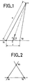
Pour obtenir que daux radars R1 at R2, tels que représentés sur la figure 1, émettent des faisceaux fournissant une concordance da phase à un point M éloigné situé dans l'angle solide commun aux deux faisceaux radars, il suffit que l'espacement E des radars, mesuré perpendiculairement à la direction des faisceaux-radars soit k fois plus grand que l'envergure e des antennes (K≥3) par exemple. En effet:![]()
![]()
- u: vecteur unité de la direction des faisceaux radars orientés parallèlement.
- u: unit vector of the direction of radar beams oriented in parallel.
Deux franqes brillantes voisines ont des directions asymptotiques définies par des cônes de demi-angle au sommet θ1 et θ2 tels que: soit![]()
![]()
![]()
![]()
La condition k > 3 donne![]()
![]()
Cela montre qu'il existe au moins 3 franges brillantes dans le faisceau-radar dont la largeur à 3 dB est voisine de ![]()
![]()
Compte tenu de l'influence de sin 0, il peut être difficile d'obtenir un bon résultat pour des petites valeurs de 0, c'est-à-dire pour des directions de rayonnement proches de la droite RlR2. Une détection de bonne qualité est néanmoins possible dans la direction de la droite R1R2 et dans les directions voisines.Given the influence of sin 0, it can be difficult to obtain a good result for small values of 0, that is to say for directions of radiation close to the line R l R 2. Detection good quality is nevertheless possible in the direction of the line R 1 R 2 and in the neighboring directions.
Dans les directions proches de la droite R1, R2 l'interfrange devient très grand à cause de la petite valeur de sin 0; pour ces directions, l'interfrange est supérieur à la largeur du faisceau commun aux 2 radars, il se peut qu'une combinaison de phase 0,0 ou 0,1 (comme défini ci-après) corresponde à une frange sombre mais dans ce cas l'autre combinaison correspond à une frange brillante. Il existe aussi des cas (dépendants du déphasage initial 1,2) pour lesquels les combinaisons 0,0 et 0,1 correspondent l'une comme l'autre à des valeurs intermédiaires pour l'intensité des franges.In the directions close to the line R1, R2 the interfringe becomes very large because of the small value of sin 0; for these directions, the interfringe is greater than the width of the beam common to the 2 radars, it may be that a phase combination 0.0 or 0.1 (as defined below) corresponds to a dark fringe but in this the other combination corresponds to a bright fringe. There are also cases (dependent on the initial phase shift 1 , 2 ) for which the combinations 0.0 and 0.1 both correspond to intermediate values for the intensity of the fringes.
Comme on l'a vu précédemment, on doit effectuer à la réception, l'addition vectorielle des champs diffrectés. Pour que le trattement soit optimal, compte tenu du bruit thermique ou du broullage supposé fortement décorrélé entre les antennes, il faut effectuer l'addition vectorielle des signaux élémentaires reçus par chacun des raders avec une correction de phase convenable Δθ; Δθ représente la correction de phase introduite per exemple dans le récepteur du radar R2 par rapport su récepteur du radar R1; sa valeur doit être telle que, pour un écho provenant d'un objectif situé au centre d'une frange brillante de H(M), las signaux reçus par chacun des radars soient mis en phase avant leur addition. Lorsque les récepteurs-radars ont même déphasage entre eux et même référence de phase, la mise en phase des signaux est obtenue en rendant la valeur absolue des Δθ égale à la valeur absolue du déphasage relatif des 2 radars à l'émission. Le signe de Δθ est choisi pour que le récepteur qui est en avance de phase à la réception corresponde au radar ayant l'avance de phase à l'émission. Dans ces conditions, le vecteur somme résultant est maximisé; on dira, dans la suite, qu'il y a coïncidence des franges d'interférence à l'émission et à la réception. En effet, H(M) est alors, proportionnel à l'intensité de l'écho reçu après addition vectorielle, M étant cette fois-ci la position d'un objectif qui rayonnerait une puissance unitaire; lorsque Δθ a la valeur convenable, l'écho d'un objectif situé au centre d'une frange brillante correspond à un rapport signal/bruit qui est 23 fois plus grand que celui qui serait obtenu avec un seul émetteur-récepteur, c'est-à-dire avec un seul radar. Il y a en effet:
- - à l'illumination (émission) un gain de 22 (en puissance) dû à l'addition des champs,
- - à la réception, un gain de 2 sur le rapport signal/bruit d'un seul radar, si les bruits des 2 radars sont décorrélés, ce qui est pratiquement toujours le cas pour le bruit thermique et peut se produire, partiellement au moins, pour le bruit induit par un brouillage.
- - on illumination (emission) a gain of 2 2 (in power) due to the addition of the fields,
- - on reception, a gain of 2 on the signal / noise ratio of a single radar, if the noises of the 2 radars are decorrelated, which is almost always the case for thermal noise and can occur, at least partially, for noise induced by interference.
En présence d'un brouillage actif dans les conditions les plus mauvaises qui donneraient des bruits totalement corrélés pour les 2 radars, le gain global serait ramené à 22 et resterait néanmoins très important; il correspondrait alors uniquement au gain à l'émission.In the presence of active interference under the worst conditions which would give completely correlated noise for the 2 radars, the overall gain would be reduced to 2 2 and would nevertheless remain very significant; it would then correspond only to the gain on issue.
Comme cela a été dit plus haut, on modifie un nombre de fois suffisant mais réduit (fonction du nombre p de radars) les relations de phase entre les émetteurs radars pour décaler le système de franges d'interférences entre les radars. Ceci a pour but de faire effectuer par les franges brillantes un balayage par pas des directions de l'espace situées à l'intérieur du faisceau commun aux radars. Cette modification de phase est faite soit d'impuision à impulsion soit de rafale à rafale lorsque les radars effectuent un traitement de signal qui utilise des techniques de cohérence (intégration cohérente, filtrage Doppler, etc....)As mentioned above, a sufficient but reduced number of times is modified (depending on the number p of radars) the phase relationships between the radar transmitters in order to shift the system of interference fringes between the radars. The purpose of this is to make the shiny fringes scan in steps the directions of the space located inside the beam common to the radars. This phase modification is made either from impulse to impulse or from burst to burst when the radars perform a signal processing which uses coherence techniques (coherent integration, Doppler filtering, etc.).
Le cas le plus simple est celui où il n'existe que 2 radars; on peut alors modifier une seule fois la relation de phase entre les 2 émetteurs en passant de ϕ à φ + π; ceci permet de permutter le réseau de franges brillantes et le réseau de franges sombres; de cette façon, on crée un balayage grossier des directions de l'espace situées à l'intérieur du faisceau commun aux deux radars. Si l'on veut améliorer la finesse du balayage, on passera de φ à φ +2π3 puis à φ + 4π3. Mais cela nécessitera 3 émissions (ou 3 rafales) successives.The simplest case is that where there are only 2 radars; we can then modify the phase relationship between the 2 transmitters only once, going from ϕ to φ + π; this allows the network of bright fringes and the network of dark fringes to be permuted; in this way, a coarse scan of the directions of space located inside the beam common to the two radars is created. If we want to improve the smoothness of the scan, we will go from φ to φ + 2π3 then to φ + 4π3. But this will require 3 successive transmissions (or 3 bursts).
Dans le cas de 3 radars, le balayage grossier des directions de l'espace situées à l'intérieur du faisceau commun aux 3 radars correspond à 4 émissions (ou 4 rafales) successives définies comme suit:
soit φ 12 et φ13 les déphasages respectifs entre les émetteurs 1 et 2, puis 1 et 3 au cours de la première impulsion (ou de la première rafale).In the case of 3 radars, the coarse scanning of the directions of space located inside the beam common to the 3 radars corresponds to 4 successive transmissions (or 4 bursts) defined as follows:
either φ 12 and φ 13 the respective phase shifts between the
La deuxième impulson (ou rafale) consiste à:
- 1. maintenir constante 12
- 2 . passer de φ13 à φ 13 + π.
- 1. maintain constant 12
- 2 . go from φ 13 to φ 13 + π.
La troisième impulsion (en rafale) consiste à:
- 1. passer de φ12 à φ12 + n
- 2. maintenir constant φ13.
- 1. go from φ 12 to φ 12 + n
- 2. maintain constant φ 13 .
La quatrième impulsion (ou rafale) consiste à:
- 1. passer de φ12 à φ12 + π
- 2. passer de φ13 à φ13 + π
- 1. go from φ 12 to φ 12 + π
- 2. go from φ 13 to φ 13 + π
On peut schématiquement représenter les 4 émissions (ou rafales) successives par les nombres binaires:

La première colonne à gauche (toujours 0) correspond au radar n° 1; la deuxième colonne correspond au radar 2; la troisième colonne au radar 3.The first column on the left (always 0) corresponds to radar n ° 1; the second column corresponds to
Le chiffre 0 placé dans la 2ème colonne indique que la relation de phase entre les 2 premiers radars est maintenue constante, sa valeur (quelconque) est appelée φ12; le chiffre 1 placé dans la 2ème colonne indique que la valeur précédente passe de φ12 à φ12 + n. La 3ème colonne indique le déphasage entre le radar n° 3 et le radar 1; le chiffre 0 indique que le déphasage entre les 2 radars est maintenu constant à sa valeur initiale (quelconque) φ13; le chiffre 1 indique que le déphasage passe de la valeur φ13 à φ13 + n.The number 0 placed in the 2nd column indicates that the phase relationship between the first 2 radars is kept constant, its (any) value is called φ 12 ; the
On considère maintenant un système à un nombre quelconque p de radars.We now consider a system with any number p of radars.
Soit R1, R2, R3, R4,... ces radars et Hl, H2, H3, H4 les champs émis correspondants.Let R 1 , R 2 , R 3 , R 4 , ... these radars and H l , H 2 , H 3 , H 4 be the corresponding transmitted fields.
Une solution consiste à placer les radars de façon que:![]()
![]()
![]()
![]()
Pour simplifier l'exposé, on se placera dans le cas où tous les radars sont alignés et rangés par indice croissant sans limiter l'invention à cette hypothèse (cf. figure 7).To simplify the presentation, we will place ourselves in the case where all the radars are aligned and arranged by increasing index without limiting the invention to this hypothesis (cf. FIG. 7).
On voit que l'interfrange entre le radar 1 et le radar i est d'autant plus fine que la valeur de i est plus grande. Dans ces conditions, lorsque l'on se déplace à très grande distance sur une sphère S ayant R1 pour centre et ceci dans un plan passant par la droite R1R2R3, la phase du champ H1 reste constante et la vitesse de rotation de phase du champ H; est d'autant plus rapide que i est plus grand. On conçoit que pour des valeurs suffisantes des valeurs de k', k",... k(p - 2), il soit possible de trouver sur la sphère S des points pour lesquels tous les champs H; sont en phase à ± 10° ou ± 30° près par exemple; la condition 1 est alors pratiquement obtenue pour ces points et leur voisinage.We see that the interfrange between
La généralisation au cas de p radars R1' R2,... Ri,...ne présente pas de difficulté; on peut prendre par exemple le radar R1 comme référence et introduire dans les chaînes de réception des déphasages différentiels Δθ12, Δθ13, Δθ14,... mesurés par rapport au radar R1; la valeur des Δθ1i est déterminée comme précédemment à partir de la mesure du déphasage de l'émission de chacun des radars par rapport à R1.Generalization in the case of p radars R 1 ' R 2 , ... R i , ... presents no difficulty; we can take for example the radar R 1 as a reference and introduce into the reception chains differential phase shifts Δθ 12 , Δθ 13 , Δθ 14 , ... measured with respect to the radar R 1 ; the value of Δθ 1i is determined as above from the measurement of the phase shift of the emission of each of the radars with respect to R 1 .
Dans le cas d'une variation de phase de π radians d'une émission à l'autre pour certains radars, on réalise, par exemple, une suite de 2p-1 émissions (ou rafales), les variations de phase étant schématisées par les 2p-1 nombres binaires suivants:In the case of a phase variation of π radians from one emission to another for certain radars, we carry out, for example, a sequence of 2 p-1 transmissions (or bursts), the phase variations being shown diagrammatically by the following 2 p-1 binary numbers:
radar

Dans la colonne i la présence d'un 0 indique que l'on a maintenu constant le déphasage π entre l'émetteur n° 1 et l'émetteur n° i, la présence d'un 1 indique que le déphasage entre les 2 radars considérés est passé de φ1,i à φ1.i + n.In column i the presence of a 0 indicates that the phase shift π between transmitter n ° 1 and transmitter n ° i has been kept constant, the presence of a 1 indicates that the phase shift between the 2 radars considered went from φ 1, i to φ 1.i + n.
Dans le cas de 2 radars avec un balayage en 3 pes, les émissions (ou rafales) successives sont représentées par les nombres suivants écrits dans un système à base 3.

Pour p radars et un balayage en 3 pas pour chaque radar, les émissions (en rafales) successives sont symbolisées par

Pour la colonne i, la présence d'un 0 indique que la déphase du ième radar est maintenu constante (égal à φ 1,i quelconque), la présence d'un 1 indique que φ1,i est remplacé par φ1,i + 2π3 la présence d'un 2 indique que φ1,i est remplacé par φ1,i + 4π 3.For column i, the presence of a 0 indicates that the phase of the i-th radar is kept constant (equal to any φ 1, i ), the presence of a 1 indicates that φ 1 , i is replaced by φ 1, i + 2π3 the presence of a 2 indicates that φ 1, i is replaced by φ 1, i +
Selon une variante de l'invention, on prévoit trois radars R1, R2, R3 qui, au lieu d'être alignés, sont placés aux sommets d'un triangle. A titre d'exemple, comme celà est représenté sur la figure 2, ce triangle peut être équilatéral.According to a variant of the invention, three radars R1, R2, R3 are provided which, instead of being aligned, are placed at the vertices of a triangle. As an example, as shown in Figure 2, this triangle can be equilateral.
Le volume de recherche et de poursuite est alors centré de préférence sur la normale au plan du triangle qui passe par l'horthocentre du triangle.The search and tracking volume is then preferably centered on the normal to the plane of the triangle which passes through the orthocenter of the triangle.
L'existence des franges très brillantes, correspondant pratiquement à la mise en phase des 3 champs, est démontrable. En effet, d'une part, le système d'interférence entre R, et R2 est un réseau hyperboloïde de révolution autour de la droite RIR2, d'autre part le système d'interférence entre R, et R3 est un réseau hyperboloïde de révolution autour de la droite RlR3. Ces deux réseaux se coupent dans l'espace, il existe nécessairement des points (en fait des directions asymptotiques) où les trois champs émis par les radars sont en phase.The existence of very bright fringes, practically corresponding to the phasing of the 3 fields, is demonstrable. Indeed, on the one hand, the interference system between R, and R 2 is a hyperboloid network of revolution around the line R I R 2 , on the other hand, the interference system between R, and R 3 is a hyperboloid network of revolution around the line R l R 3 . These two networks intersect in space, there necessarily exist points (in fact asymptotic directions) where the three fields emitted by the radars are in phase.
Selon une autre variante de l'invention représentée sur la figure 3, on combine la disposition en triangle précédente avec des dispositions alignées. C'est ainsi que cinq radars R1 à R5 sont disposés aux sommets de deux triangles équilatéraux ayant en commun un angie au sommet, l'angle R1 par exemple. Les radars R1, R3, R5 sont donc alignés ainsi que les radars R1, R2 et R4.According to another variant of the invention shown in FIG. 3, the arrangement in the preceding triangle is combined with aligned arrangements. Thus five radars R1 to R5 are arranged at the vertices of two equilateral triangles having in common an angia at the vertex, the angle R1 for example. The radars R1, R3, R5 are therefore aligned as well as the radars R1, R2 and R4.
On peut également, selon une variante de l'invention représentée sur la figure 4, disposer les radars aux sommets de deux triangles quelconques ayant un sommet commun, mais ayant des dimensions très différentes.It is also possible, according to a variant of the invention shown in FIG. 4, to have the radars at the vertices of any two triangles having a common vertex, but having very different dimensions.
Une autre variante de l'invention représentée en figure 8, consiste à utiliser deux groupes de radars alignés R1, R2, R3, R4 et R1, R'2, R'3, R'4, les droites R1, R2, R3 R4 et R1, R'2, R'3, R'4 formant entre elles un angle compris entre 50° et 180° - 30° = 150° par exemple; les distances entre les radars (R1, R2), (R1, R3), (R1, R4) étant soumises aux conditions:![]()
![]()
![]()
![]()
![]()
![]()
![]()
![]()
En se reportant à la figure 5, on va maintenant décrire un exemple de circuits permettant de mettre en oeuvre l'invention.Referring to Figure 5, we will now describe an example of circuits for implementing the invention.
Ces circuits sont appliqués au cas de deux radars. Ils permettent de:
- 1. mesurer le déphasage entre les signaux d'émission.
- 2. introduire dans les chaînes de réception le déphasage différentiel de compensation Δφ défini plus haut en valeur absolue et signe.
- 3. sommer les signaux résultant après correction de la phase.
- 1. measure the phase difference between the transmission signals.
- 2. introduce into the reception chains the differential compensation phase shift Δφ defined above in absolute value and sign.
- 3. summing the resulting signals after phase correction.
Dans l'exemple donné, les ensembles de réception sont supposés avoir deux à deux des temps de transmission égaux et des déphasages égaux entre leurs entrées et leurs sorties correspondantes telles qu'elles sont définies pour la comparaison des radars deux à deux.In the example given, the reception sets are supposed to have two by two equal transmission times and equal phase shifts between their inputs and their corresponding outputs as defined for the comparison of radars two by two.
L'égalité des temps de transmission et des déphasages entre les entrées et les sorties correspondante peut être obtenu soit directement par construction, soit indirectement par compensation après mesure des écarts, cette mesure étant faite par injection d'un signal de test dans chaque chaîne.The equality of the transmission times and the phase shifts between the corresponding inputs and outputs can be obtained either directly by construction, or indirectly by compensation after measurement of the deviations, this measurement being made by injecting a test signal into each chain.
L'homme de l'art sait obtenir ces égalités notamment dans l'exploitation des techniques monopulses.Those skilled in the art know how to obtain these equality, in particular in the exploitation of monopulse techniques.
La mesure de la différence de phase entre les émissions peut être faite suivant la figure 5 où l'on trouve deux radars 1 et 2 comportant chacun un émetteur (E1, E2), un récepteur (REC1, REC2), un duplexeur (D1, D2) connectant l'émetteur et le récepteur à une antenne (A1, A2). Chaque radar possède en outre, selon l'invention, dans la chaîne de réception, un déphaseur (DEPH1, DEPH2) recevant de l'amplificateur (REC1, REC2) le signal préamplifié et le transmettant à l'amplificateur (REC'1, REC'2) après introduction d'un déphasage commandable.The measurement of the phase difference between the transmissions can be made according to Figure 5 where there are two
Les deux radars sont couplés par deux coupleurs directifs (CP1, CP2) à un guide d'onde G unique.The two radars are coupled by two directional couplers (CP1, CP2) to a single G waveguide.
Associé au radar 1, un premier système de mesure de déphasage S1 à deux entrées e1 et e'1 couplées au guide d'onde G par deux coupleurs directifs CM1 et CM'1 convenablement orientés.Associated with
De même, associé à l'autre radar 2, un deuxième système de mesure de déphasage S2 possède deux entrées e2 et e'2 couplées, par des coupleurs directifs (CM2 et CM'2) convenablement orientés, au guide d'onde G.Similarly, associated with the
La longueur électrique de la voie reliant les coupleurs directifs CP1 et CM1 est égale à celle de la voie reliant les coupleurs directifs CP2 et CM2. La liaison CM1-CM'1 est identique à la liaison CM2-CM'2.The electrical length of the track connecting the directional couplers CP1 and CM1 is equal to that of the track connecting the directional couplers CP2 and CM2. The CM1-CM'1 link is identical to the CM2-CM'2 link.
De même la longueur électrique de la voie reliant le coupleur directif CP1 à la sortie du récepteur REC'1 est égale à celle de la voie reliant le coupleur CP2 à la sortie du récepteur REC'2 et cela lorsque les deux déphaseurs DEPH 1 et DEPH 2 sont en position de déphasage nul.Similarly, the electrical length of the channel connecting the directional coupler CP1 to the output of the receiver REC'1 is equal to that of the channel connecting the coupler CP2 to the output of the receiver REC'2 and this when the two phase shifters DEPH 1 and
Les systèmes de mesure de phase S1, S2 permettent de mesurer les différences de phase des signaux à l'émission des deux radars 1 et 2. Les résultats de ces mesures sont transmis à un circuit de différence et de commande UC. Ces circuits permettent d'obtenir la valeur de la différence de phase 02 - 01 des signaux à l'émission. Plus précisément, ils permettent d'obtenir la valeur 2 (02 - 01). En fonction de la valeur de déphasage obtenue, les circuits UC commandent les déphaseurs DEPH1 et DEPH2. On introduit ainsi un déphasage différentiel comme celà va être décrit ci-après.The phase measurement systems S1, S2 make it possible to measure the phase differences of the signals on transmission from the two
Le signal d'émission de chacun des radars est envoyé vers l'autre par l'intermédiaire d'un guide unique G où les deux signaux d'émission se propagent en sens inverses. Ces signaux d'émission sont prélevés sur les radars 1 et 2 par les coupleurs directifs respectifs CP1 et CP2 placés sur la voie commune à l'émission et à la réception de chaque radar. Pour la suite de la description, il est commode de considérer, pour chaque coupleur CP1 et CP2, un plan de référence respectivement PR11 et PR21, ces deux plans de référence étant situés de manière analogue à l'intérieur des coupleurs. Ces deux plans définissent l'entrée des voies de réception de chaque radar.The emission signal from each of the radars is sent to the other via a single guide G where the two emission signals propagate in opposite directions. These transmission signals are taken from
A chaque extrémité du guide G se trouvent placés deux systèmes S1 et S2 de mesure de déphasage. Ces deux systèmes sont identiques. Le système S1 mesure le déphasage M1 entre le signal de l'émission locale du radar 1 et le signal de l'émission du radar 2 reçu par l'intermédiaire du guide G. A l'inverse, le système de mesure S2 mesure le déphasage M2 entre le signal de l'émission locale du radar 2 et le signal de l'émission du radar 1 reçu par l'intermédiaire du guide G.At each end of the guide G are placed two systems S1 and S2 of phase shift measurement. These two systems are identical. The system S1 measures the phase shift M1 between the signal of the local emission of the
Les deux systèmes de mesure S1 et S2 prélèvent les signaux soumis aux mesures par l'intermédiaire des coupleurs respectifs CM1, CM'1 et CM2, CM'2. Le coupleur CM1 fournit sur l'entrée e1 du système de mesure S1, le signal local du radar 1. Le coupleur CM'1 fournit à l'entrée e'1 du système de mesure S1, le signal d'émission du radar 2 transmis par le guide G. De la même façon, le coupleur CM2 fournit à l'entrée e2 du système S2, le signal local d'émission du radar 2 et le coupleur CM'2 fournit à l'entrée e'2. le signal d'émission du radar 1 transmis par le guide G.The two measurement systems S1 and S2 take the signals subjected to the measurements via the respective couplers CM1, CM'1 and CM2, CM'2. The coupler CM1 supplies the local signal from
Les deux ensembles de coupleurs CP1, CM1, CM'1 d'une part et CP2, CM2 et CM'2 d'autre part sont identiques ainsi que leurs connexions internes. Tous les coupleurs directifs sont munis d'une charge adaptée dans la quatrième voie conformément aux règles de l'art.The two sets of couplers CP1, CM1, CM'1 on the one hand and CP2, CM2 and CM'2 on the other hand are identical as well as their internal connections. All directional couplers are fitted with a suitable load in the fourth channel in accordance with good practice.
Le système de mesure S1 mesure donc la différence de phase M1 = 01 - 02.The measurement system S1 therefore measures the phase difference M1 = 0 1 - 0 2 .
01 étant la phase du signal d'émission du radar 1.0 1 being the phase of the
Ø'2 étant la phase du signal d'émission du radar 2 reçu par le guide G.Ø ' 2 being the phase of the
Le système de mesure S2 mesure la différence de phase M2 = 02 - 0'1' The S2 measurement system measures the phase difference M2 = 0 2 - 0 '1'
0. étant la phase du signal d'émission du radar 2,0 . being the phase of the
0'1 étant la phase du signal d'émission du radar 1 reçu par le guide G.0 ' 1 being the phase of the
Pour des raisons de symétrie 01 et 02 représentent à une même constante près les phases d'émission respectivement dans les plans de référence PR1 et PR2. Pour des raisons de symétrie, on a:![]()
![]()
![]()
![]()
Des quatres égalités précédentes, on déduit:![]()
![]()
Grâce aux propriétés de symétrie et à l'existence d'un guide de liaison unique G on a mesuré le déphasage entre les émissions des radars 1 et 2 dans les plans de référence PR1 et PR2 ceci sans avoir à connaître la longueur du guide G.Thanks to the properties of symmetry and the existence of a single link guide G, the phase difference between the emissions from
En application du principe de retour inverse, la réception des signaux renvoyés par une cible située sur une frange brillante se fera avec le même déphasage relatif dans les plans de référence.In application of the reverse return principle, the reception of the signals returned by a target located on a bright fringe will be done with the same relative phase shift in the reference planes.
Le radar dont l'émission est en avance de phase recevra un signal en retard de phase. Pour mettre en phase les 2 signaux reçus par les radars 1 et 2, il y a donc lieu de donner une avance de phase au récepteur correspondant à l'émission en avance de phase.The radar whose emission is in phase advance will receive a signal in phase delay. To phase the 2 signals received by
La figure 5 représente les déphaseurs DEPH1 et DEPH2 insérés entre deux récepteurs REC1, REC'1 pour l'un des déphaseurs et REC2, REC'2 pour l'autre déphaseur. En réalité, ces couples de récepteurs REC1 - REC'1 et REC2 - REC'2 forment chacun un organe unique, un déphaseur (DEPH1, DEPH2) étant placé à l'intérieur de chaque organe.FIG. 5 represents the phase shifters DEPH1 and DEPH2 inserted between two receivers REC1, REC'1 for one of the phase shifters and REC2, REC'2 for the other phase shifter. In reality, these pairs of receivers REC1 - REC'1 and REC2 - REC'2 each form a single organ, a phase shifter (DEPH1, DEPH2) being placed inside each organ.
Ces déphaseurs permettent d'effectuer une compensation du déphasage émission, mesuré comme cela a été décrit précédemment, par un déphasage à la réception.These phase shifters make it possible to compensate for the transmission phase shift, measured as described above, by a phase shift at reception.
Un circuit de calcul de différence et de commande UC permet en fonction des résultats de mesure M1 et M2 effectués par les sytèmes de mesures S1 et S2 d'effectuer la différence M1 et M2 et de commander en conséquence les déphaseurs DEPH1 et DEPH2.A difference calculation and control circuit UC makes it possible as a function of the measurement results M1 and M2 carried out by the measurement systems S1 and S2 to effect the difference M1 and M2 and to control the phase shifters DEPH1 and DEPH2 accordingly.
On notera que le réglage de l'égalité des temps de transfert entre les entrées et les sorties des deux chaînes de réception doit se faire avec des déphasages nuls (ou rigoureusement égaux) des déphaseurs DEPH1 et DEPH2, c'est-à-dire pour des temps de transfert et des déphasages égaux pour chaque chaîne.It will be noted that the adjustment of the equality of the transfer times between the inputs and outputs of the two reception chains must be done with zero phase shifts (or strictly equal) of the phase shifters DEPH1 and DEPH2, that is to say for equal transfer times and phase shifts for each chain.
Le système de mesure de déphasage conforme à l'invention peut comporter un nombre n de radars. A titre d'exemple, la figure 6 représente un système à quatre radars.The phase shift measurement system according to the invention may include a number n of radars. By way of example, FIG. 6 represents a system with four radars.
La mesure des déphasages à l'émission est faite par des comparaisons séparées qui prennent toutes comme référence le radar 1 et utilisent respectivement des guides G2, G3, G4 pour propager dans les 2 sens les signaux à comparer. Le couplage de G2, G3, G4 est fait respectivement au radar 1 par les coupleurs CP 1.2, CP 1.3 et CP 1.4. Les couplages respectifs aux radars 2, 3 et 4 sont faits par les coupleurs CP2, CP3 et CP4.The measurement of the phase shifts on transmission is made by separate comparisons which all take
Pour conserver la symétrie des radars deux à deux il est préférable de placer sur la voie émission-réception du radar 1 autant de coupleurs directifs qu'il y a d'autres radars à comparer et à associer. L'égalité des temps de transfert et des déphasages entrée-sortie à la réception est réalisée comme suit:To preserve the symmetry of radars two by two it is preferable to place on the transmission-reception channel of
- pour les radars 1 et 2, on réalise l'égalité des chemins électriques suivants: coupleur CP 1.2, sortie de REC'1 = coupleur CP2, sortie de REC'2, - pour les radars 1 et 3, on réalise l'égalité des chemins électriques suivants: coupleur CP 1.3, sortie REC'1 = coupleur CP3, sortie REC'3, - pour les radars 1 et 4, on réalise l'égalité des chemins électriques suivants: coupleur CP 1.4, sortie REC'1 = coupleur CP4, sortie REC'4.- for
A titre général, comme décrit en se reportant à la figure 5, les chemins homologues d'un couple de radars, tel que le couple 1-2 par exemple, sont prévus de longueurs égales.In general, as described with reference to FIG. 5, the homologous paths of a pair of radars, such as the pair 1-2 for example, are provided with equal lengths.
A chaque guide d'onde G2, G3, G4 sont couplés deux systèmes de mesure de déphasages similaires aux systèmes S1 et S2 de la figure 5.To each waveguide G2, G3, G4 are coupled two phase-shift measurement systems similar to the systems S1 and S2 of FIG. 5.
Par exemple, au guide d'onde G3, sont couplés, d'une part, un système de mesure de déphasage S 1.3 par des coupleurs CM 1.3 et CM' 1.3 et, d'autre part, un système de mesure de déphasage S3 par des coupleurs CM3 et CM'3.For example, to the waveguide G3, are coupled, on the one hand, a phase shift measurement system S 1.3 by couplers CM 1.3 and CM '1.3 and, on the other hand, a phase shift measurement system S3 by CM3 and CM'3 couplers.
Les deux systèmes de mesure de déphasages associés à un même guide d'onde fournissent leurs résultats de mesure à un circuit de différence et de commande non représenté sur la figure 6 et permettent de commander les déphaseurs des radars associés à ce guide d'onde.The two phase-shift measurement systems associated with the same waveguide supply their measurement results to a difference and control circuit not shown in FIG. 6 and make it possible to control the phase shifters of the radars associated with this waveguide.
Le fonctionnement du système de la figure 6 est donc identique à celui décrit pour les radars 1 et 2 de la figure 5 en considérant séparément le fonctionnement des couples de radars 1-2, 1-3 et 1-4.The operation of the system in FIG. 6 is therefore identical to that described for
Il est bien évident qu'un fonctionnement avec un plus qrand nombre de radars serait similaire en prévoyant également des couples de radars.It is quite obvious that operation with a larger number of radars would be similar by also providing for pairs of radars.
La figure 9 indique la manière d'introduire les déphasages π ou et 4f dans les émetteurs E2, E3,... etc par rapport à l'émetteur E1. Les émetteurs sont généralement terminés par un tube amplificateur de puissance A si bien qu'il est préférable d'introduire les déphasages ci-dessus à bas niveau à l'entrée de l'amplificateur de puissance par un déphasage commandé DE à la sortie du pilote Pi. La référence de fréquence des pilotes P1, P2, Pi... peut être unique donc commune; mais il est possible également que chaque pilote Pi ait sa propre référence de fréquence (par exemple, une horloge atomique) telle que sa grande stabilité évite tout glissement de fréquence pendant la durée des émissions ou des rafales qui doivent être faites à la même fréquence c'est-à-dire pendant les 2P-1 ou 3p-l émissions ou rafales successives qui assurent le balayage par pas de l'espace à l'intérieur du faisceau commun aux radars.FIG. 9 indicates the way of introducing the phase shifts π or and 4f into the transmitters E2, E3, ... etc. with respect to the transmitter E1. The transmitters are generally terminated by a power amplifier tube A so that it is preferable to introduce the above phase shifts at low level at the input of the power amplifier by a controlled phase shift DE at the output of the pilot Pi. The frequency reference of the pilots P1, P2, Pi ... can be unique therefore common; but it is also possible that each Pi pilot has its own frequency reference (for example, an atomic clock) such that its high stability prevents any frequency sliding during the duration of the transmissions or bursts which must be made at the same frequency c that is to say during the 2P- 1 or 3 pl successive transmissions or gusts which ensure the scanning in steps of the space inside the beam common to the radars.
Claims (11)
Applications Claiming Priority (2)
| Application Number | Priority Date | Filing Date | Title |
|---|---|---|---|
| FR8412134 | 1984-07-31 | ||
| FR8412134A FR2568686B1 (en) | 1984-07-31 | 1984-07-31 | MULTIPLE NEIGHBOR RADAR OPERATING SYSTEM |
Publications (2)
| Publication Number | Publication Date |
|---|---|
| EP0172094A1 EP0172094A1 (en) | 1986-02-19 |
| EP0172094B1 true EP0172094B1 (en) | 1989-07-12 |
Family
ID=9306669
Family Applications (1)
| Application Number | Title | Priority Date | Filing Date |
|---|---|---|---|
| EP85401544A Expired EP0172094B1 (en) | 1984-07-31 | 1985-07-26 | Operational system for a plurality of closely located radars |
Country Status (3)
| Country | Link |
|---|---|
| EP (1) | EP0172094B1 (en) |
| DE (1) | DE3571507D1 (en) |
| FR (1) | FR2568686B1 (en) |
Families Citing this family (2)
| Publication number | Priority date | Publication date | Assignee | Title |
|---|---|---|---|---|
| EP1149306B1 (en) * | 1999-01-07 | 2003-04-02 | Siemens Aktiengesellschaft | Method for detecting targets and for determining their direction for a radar device in a motor vehicle |
| GB2357918A (en) | 1999-09-30 | 2001-07-04 | Alenia Marconi Systems Ltd | HF Radar Tx/Rx assembly |
Family Cites Families (1)
| Publication number | Priority date | Publication date | Assignee | Title |
|---|---|---|---|---|
| US3454944A (en) * | 1968-03-13 | 1969-07-08 | United Aircraft Corp | Wide-angle interferometer radar |
-
1984
- 1984-07-31 FR FR8412134A patent/FR2568686B1/en not_active Expired
-
1985
- 1985-07-26 EP EP85401544A patent/EP0172094B1/en not_active Expired
- 1985-07-26 DE DE8585401544T patent/DE3571507D1/en not_active Expired
Non-Patent Citations (1)
| Title |
|---|
| M.I.Skolnik, Introduction to Radar Systems, Mac-Graw-Hill, Tokyo (JP), 1980, pp. 280-283 * |
Also Published As
| Publication number | Publication date |
|---|---|
| EP0172094A1 (en) | 1986-02-19 |
| DE3571507D1 (en) | 1989-08-17 |
| FR2568686A1 (en) | 1986-02-07 |
| FR2568686B1 (en) | 1986-12-05 |
Similar Documents
| Publication | Publication Date | Title |
|---|---|---|
| EP0600799B1 (en) | An active antenna with variable polarisation synthesis | |
| EP2312335B1 (en) | Radar with high angular precision, in particular for the function for detecting and avoiding obstacles | |
| EP2831615B1 (en) | Device for active and passive electromagnetic detection with a low likelihood of interception | |
| EP0143497B1 (en) | Axis-stable fmcw monopulse radar system | |
| FR2948774A1 (en) | RADAR FOR DETECTING AIR TARGETS EQUIPPED WITH AN AIRCRAFT, IN PARTICULAR FOR THE AVOIDANCE OF OBSTACLES IN FLIGHT | |
| EP3819670A1 (en) | Processing method for coherent mimo radar system processing ddma waveforms | |
| WO1992019985A1 (en) | Echo ranging system having a calibration device | |
| FR2661561A1 (en) | OMNIDIRECTIONAL COVERAGE RADIOGONIOMETRY ANTENNA SYSTEM. | |
| EP0172094B1 (en) | Operational system for a plurality of closely located radars | |
| WO2010136461A1 (en) | High-precision absolute microwave telemeter with a multi-state reflection device | |
| EP2822198B1 (en) | Method and System to measure the group delay of an antenna | |
| EP3667357B1 (en) | Method for scrambling of the electronic signature transmitted by a radar, and transmitting/receiving device suitable for implementing same | |
| EP0613019B1 (en) | Off-boresight antenna for monopulse radar | |
| EP1522871B1 (en) | Radar with synthetic direction finding channels | |
| EP0624804A1 (en) | Tracking system for estimating the pointing error of a HF antenna | |
| EP0163346A1 (en) | System for aircraft terminal guidance or position reseting using range and angle measurement | |
| FR3111993A1 (en) | surveillance of space using a bistatic radar, the receiver system of which is at least partially on board a satellite | |
| FR2965632A1 (en) | Electromagnetic reflector for measuring relative displacement of object, has delaying unit for delaying reflected signal with respect to signal received by antenna, where reflector has distinct reflection coefficients | |
| FR3134458A1 (en) | RADIANT CABLE SEGMENT POSITIONING SYSTEM | |
| FR3115114A1 (en) | AMBIGUOUS ELECTRONIC SCANNING DOPPLER RADAR | |
| FR2965634A1 (en) | System for measuring distance between measuring antenna and electromagnetic reflector, has calculating unit that calculates distance from temporal positions corresponding to reflection of emitted wave on antenna | |
| FR2749399A2 (en) | Interferometer receiver for electromagnetic signals, e.g. in military radar system | |
| EP1233282A1 (en) | System with distributed transmit and receive antennas, in particular for radar with synthetic emission and beamforming | |
| FR3030771A1 (en) | METHOD OF MEASURING AN INCIDENT RISE INCIDENCE DIRECTION FOR AN INSTANT BROADBAND RECEIVER AND RECEIVER THEREOF | |
| FR2648917A1 (en) | RADAR DEVICE FOR DETECTING SHORT DISTANCE TARGETS |
Legal Events
| Date | Code | Title | Description |
|---|---|---|---|
| PUAI | Public reference made under article 153(3) epc to a published international application that has entered the european phase |
Free format text: ORIGINAL CODE: 0009012 |
|
| AK | Designated contracting states |
Designated state(s): DE GB IT NL |
|
| 17P | Request for examination filed |
Effective date: 19860630 |
|
| 17Q | First examination report despatched |
Effective date: 19880210 |
|
| RAP3 | Party data changed (applicant data changed or rights of an application transferred) |
Owner name: THOMSON-CSF |
|
| GRAA | (expected) grant |
Free format text: ORIGINAL CODE: 0009210 |
|
| AK | Designated contracting states |
Kind code of ref document: B1 Designated state(s): DE GB IT NL |
|
| ITTA | It: last paid annual fee | ||
| PGFP | Annual fee paid to national office [announced via postgrant information from national office to epo] |
Ref country code: NL Payment date: 19890731 Year of fee payment: 5 Ref country code: GB Payment date: 19890731 Year of fee payment: 5 |
|
| ITF | It: translation for a ep patent filed |
Owner name: JACOBACCI & PERANI S.P.A. |
|
| REF | Corresponds to: |
Ref document number: 3571507 Country of ref document: DE Date of ref document: 19890817 |
|
| PGFP | Annual fee paid to national office [announced via postgrant information from national office to epo] |
Ref country code: DE Payment date: 19890823 Year of fee payment: 5 |
|
| GBT | Gb: translation of ep patent filed (gb section 77(6)(a)/1977) | ||
| PLBE | No opposition filed within time limit |
Free format text: ORIGINAL CODE: 0009261 |
|
| STAA | Information on the status of an ep patent application or granted ep patent |
Free format text: STATUS: NO OPPOSITION FILED WITHIN TIME LIMIT |
|
| 26N | No opposition filed | ||
| PG25 | Lapsed in a contracting state [announced via postgrant information from national office to epo] |
Ref country code: GB Effective date: 19900726 |
|
| PG25 | Lapsed in a contracting state [announced via postgrant information from national office to epo] |
Ref country code: NL Effective date: 19910201 |
|
| NLV4 | Nl: lapsed or anulled due to non-payment of the annual fee | ||
| GBPC | Gb: european patent ceased through non-payment of renewal fee | ||
| PG25 | Lapsed in a contracting state [announced via postgrant information from national office to epo] |
Ref country code: DE Effective date: 19910403 |