EP0171994A1 - Spark plug - Google Patents
Spark plug Download PDFInfo
- Publication number
- EP0171994A1 EP0171994A1 EP85305617A EP85305617A EP0171994A1 EP 0171994 A1 EP0171994 A1 EP 0171994A1 EP 85305617 A EP85305617 A EP 85305617A EP 85305617 A EP85305617 A EP 85305617A EP 0171994 A1 EP0171994 A1 EP 0171994A1
- Authority
- EP
- European Patent Office
- Prior art keywords
- noble metal
- leading end
- electrode
- centre
- welded
- Prior art date
- Legal status (The legal status is an assumption and is not a legal conclusion. Google has not performed a legal analysis and makes no representation as to the accuracy of the status listed.)
- Granted
Links
- 229910000510 noble metal Inorganic materials 0.000 claims abstract description 138
- 229910000990 Ni alloy Inorganic materials 0.000 claims description 10
- 229910045601 alloy Inorganic materials 0.000 claims description 10
- 239000000956 alloy Substances 0.000 claims description 10
- 229910002835 Pt–Ir Inorganic materials 0.000 claims description 8
- 229910001260 Pt alloy Inorganic materials 0.000 claims description 7
- 229910002845 Pt–Ni Inorganic materials 0.000 claims description 7
- BASFCYQUMIYNBI-UHFFFAOYSA-N platinum Substances [Pt] BASFCYQUMIYNBI-UHFFFAOYSA-N 0.000 claims description 6
- PXHVJJICTQNCMI-UHFFFAOYSA-N nickel Substances [Ni] PXHVJJICTQNCMI-UHFFFAOYSA-N 0.000 claims description 5
- RYGMFSIKBFXOCR-UHFFFAOYSA-N Copper Chemical group [Cu] RYGMFSIKBFXOCR-UHFFFAOYSA-N 0.000 claims description 3
- 229910052741 iridium Inorganic materials 0.000 claims description 2
- 229910000575 Ir alloy Inorganic materials 0.000 claims 1
- 239000010953 base metal Substances 0.000 claims 1
- 238000012986 modification Methods 0.000 description 11
- 230000004048 modification Effects 0.000 description 11
- 238000003466 welding Methods 0.000 description 9
- 238000000034 method Methods 0.000 description 6
- 239000012212 insulator Substances 0.000 description 5
- 229910018879 Pt—Pd Inorganic materials 0.000 description 4
- 230000003247 decreasing effect Effects 0.000 description 4
- 238000004519 manufacturing process Methods 0.000 description 4
- 229910052751 metal Inorganic materials 0.000 description 4
- 239000002184 metal Substances 0.000 description 4
- 238000012360 testing method Methods 0.000 description 4
- 230000002411 adverse Effects 0.000 description 3
- 230000000694 effects Effects 0.000 description 3
- 238000010438 heat treatment Methods 0.000 description 3
- 230000003647 oxidation Effects 0.000 description 3
- 238000007254 oxidation reaction Methods 0.000 description 3
- 238000000926 separation method Methods 0.000 description 3
- 229910018967 Pt—Rh Inorganic materials 0.000 description 2
- 230000015556 catabolic process Effects 0.000 description 2
- 238000002485 combustion reaction Methods 0.000 description 2
- 238000001816 cooling Methods 0.000 description 2
- 230000007797 corrosion Effects 0.000 description 2
- 238000005260 corrosion Methods 0.000 description 2
- 238000006731 degradation reaction Methods 0.000 description 2
- 230000001419 dependent effect Effects 0.000 description 2
- 238000006073 displacement reaction Methods 0.000 description 2
- 229910001055 inconels 600 Inorganic materials 0.000 description 2
- 230000035882 stress Effects 0.000 description 2
- 229910000838 Al alloy Inorganic materials 0.000 description 1
- 229910019589 Cr—Fe Inorganic materials 0.000 description 1
- 229910018487 Ni—Cr Inorganic materials 0.000 description 1
- PNEYBMLMFCGWSK-UHFFFAOYSA-N aluminium oxide Inorganic materials [O-2].[O-2].[O-2].[Al+3].[Al+3] PNEYBMLMFCGWSK-UHFFFAOYSA-N 0.000 description 1
- 238000010276 construction Methods 0.000 description 1
- 230000001276 controlling effect Effects 0.000 description 1
- 238000007796 conventional method Methods 0.000 description 1
- 230000002596 correlated effect Effects 0.000 description 1
- 230000007547 defect Effects 0.000 description 1
- 229910003460 diamond Inorganic materials 0.000 description 1
- 239000010432 diamond Substances 0.000 description 1
- 238000009792 diffusion process Methods 0.000 description 1
- 238000002474 experimental method Methods 0.000 description 1
- 239000000446 fuel Substances 0.000 description 1
- 239000007789 gas Substances 0.000 description 1
- 239000011521 glass Substances 0.000 description 1
- 238000005304 joining Methods 0.000 description 1
- 238000003754 machining Methods 0.000 description 1
- 229910052759 nickel Inorganic materials 0.000 description 1
- 238000012856 packing Methods 0.000 description 1
- 230000002093 peripheral effect Effects 0.000 description 1
- 238000003825 pressing Methods 0.000 description 1
- 230000002265 prevention Effects 0.000 description 1
- 230000008646 thermal stress Effects 0.000 description 1
Images

Classifications
-
- H—ELECTRICITY
- H01—ELECTRIC ELEMENTS
- H01T—SPARK GAPS; OVERVOLTAGE ARRESTERS USING SPARK GAPS; SPARKING PLUGS; CORONA DEVICES; GENERATING IONS TO BE INTRODUCED INTO NON-ENCLOSED GASES
- H01T13/00—Sparking plugs
- H01T13/20—Sparking plugs characterised by features of the electrodes or insulation
- H01T13/32—Sparking plugs characterised by features of the electrodes or insulation characterised by features of the earthed electrode
-
- H—ELECTRICITY
- H01—ELECTRIC ELEMENTS
- H01T—SPARK GAPS; OVERVOLTAGE ARRESTERS USING SPARK GAPS; SPARKING PLUGS; CORONA DEVICES; GENERATING IONS TO BE INTRODUCED INTO NON-ENCLOSED GASES
- H01T13/00—Sparking plugs
- H01T13/20—Sparking plugs characterised by features of the electrodes or insulation
- H01T13/39—Selection of materials for electrodes
Abstract
Description
- The present invention relates to a spark plug for an internal combustion engine and more particularly a spark plug of the type in which a spark gap is defined by at least one pair of opposed centre and ground electrodes and a fine noble metal tip is welded to the leading end face of at least one of the centre and ground electrode main bodies so that energy saving can be attained and long service can be ensured.
- In spark plugs of the type described above, thin noble metal plates which are made of a platinum alloy such as Pt-Ir, Pt-Rh, Pt-Ni, Pt-Pd or the like and which exhibit high resistance to heat and wear are electrically welded to the spark discharge portions of the centre and ground electrodes. Such a spark plug as described above is disclosed in detail in US-A-2,296,033.
- However, in spark plugs of the type described, the whole volume of the centre and ground electrodes which define a spark gap is great so that the thermal energy of the flame produced in the spark gap tends to be absorbed by the centre and ground electrodes including the thin noble metal plates. As a result, there arises the problem that ignitionability is adversely affected. Meanwhile, in recently developed ignition circuits, in order to make an ignition circuit light in weight and to permit fabrication at less cost, both positive and negative voltages are applied to the spark plug while only negative voltages here applied to the spark plug in the past. The prior art spark plugs have a common defect that the discharge performance is dependent upon the polarity of the voltage applied to the spark plug.
- In order to minimize the flame extinguishing action or effect, a fine noble metal wire less than l.Omm in diameter is electrically welded to the leading end face of an electrode main body, but the welded joint between the noble metal tip and the electrode main body is too small in area so that a required joint strength cannot be obtained. Furthermore, the noble metal tip and the electrode main body have different coefficients of thermal expansion so that when the spark plugs are mounted on an engine, the noble metal tips very frequently tend to separate from the electrode main bodies and drop off in the worse case.
- In order to overcome the above problems, there has been devised and demonstrated a method in which a noble metal tip is previously formed with an enlarged flange or is fitted into a recess of the electrode main body and thereafter the leading end portion including the recess is caulked and simultaneously the noble metal tip is welded. Such a method is disclosed in detail in Japanese Patent Publication No. 56-45264. In either case, the noble metal is used in large quantities and even when the noble metal tips are formed with a flange and electrically welded to the electrode main bodies, separation of the noble metal tips from the electrode main bodies cannot always be avoided.
- According to a first aspect of the invention there is provided a spark plug of the type in which the leading end faces of a centre electrode and a ground electrode have noble metal tips, characterized in that the noble metal tip of the centre electrode is in the form of a fine wire while the noble metal tip of the ground electrode is in the form of a fine wire or a column; each of the noble metal tips being electrically welded to the leading end face of the centre or ground electrode main body in such a way that the end of the tip in contact with the centre or ground electrode main body is enlarged to form a flange.
- According to a second aspect there is provided a spark plug of the type in which a spark gap is defined at least between opposed electrodes and the leading end face of at least one of the electrodes is provided with a fine nOble-metal tip, characterized a noble metal tip in the form of a cylinder is electrically welded to the leading end face of an electrode main body, the end of the noble metal tip in contact with the leading end face of the electrode main body being enlarged to form a flange; and the diameter A of the noble metal tip, the diameter B of the flange thus formed, the thickness C thereof and the depth D of the noble metal tip embedded into the electrode main body satisfying the relationships:-
-


- The present invention provides a spark plug in which the use of an expensive noble metal is reduced to a minimum, the prevention of separation of the noble metal tip from the electrode main body is facilitated, and durality and ignitionability are improved.
- Preferably, the leading end portion of an electrode main body is in the form of a column or is tapered so that the diameter of the leading end E satisfies the relation:

- Furthermore the height or extension F of the noble metal tip above or beyond the flanged portion may satisfy the relation:

- As a result, thermal stresses in the noble metal tip can be reduced and durability can be further improved.
- According to a third aspect of the invention, the cross sectional area of a noble metal cylinder to be welded to a centre electrode is less than 0.8 mm2 and the cross section area of a noble metal body , welded to a ground electrode is less than 1.3 mm2,
- the leading end of the noble metal block welded to the ground electrode being extended beyond the leading end of the ground electrode.
- As a result, the discharge voltage can be lowered and a spark plug which is not influenced by the polarity of a voltage applied thereto can be provided. The noble metal tip welded to the centre electrode (A) is preferably extended by 0.4 - 1.5 mm from the leading end of the centre electrode (A) while the noble metal body welded to the ground electrode (B) is extended by 0.4 - 1.5 mm beyond the leading end of the ground electrode (B). Therefore, the above described discharge characteristics can be maintained, the resistance to wear can be improved and the noble metal tips or bodies are prevented from being broken.
- Examples of spark plugs constructed in accordance with the present invention will now be described with reference to the accompanying drawings, in which:-
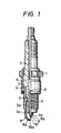
- Figure 1 is a side view, partly in section, of a first embodiment of a spark plug;
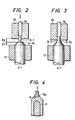
- Figures 2-4 show the steps of welding a noble metal tip to an electrode main body;
- Figure 5 shows another method for joining a noble metal tip to an electrode main body;
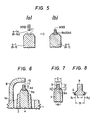
- Figure 6 is a partial view, on enlarged scale, of a second embodiment;
- Figure 7 shows the joint between a tip and an electrode main body;
- Figure 8 is a view showing the corrosions due to oxidation after tests;
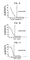
- Figures 9-11 are graphs showing the relationships between the tip-separation-danger rate on the one hand and the shape parameter, size C and size D on the other hand;
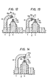
- Figures 12, 13 and 14 are partial sectional views, on enlarged scale, of some modifications of the second embodiment shown in Figure 6;
- Figure 15 is a partial front view, on enlarged scale, of a third embodiment of a spark plug;
- Figure 16 is a side view thereof;
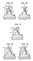
- Figures 17, 18 and 19 show modifications of the third embodiment;
- Figure 20 shows in cross section various joints between noble metal bodies and ground electrode main bodies; and,
- Figure 21 shows the shapes of the leading ends of ground electrodes.
- The spark plug shown in Figures 1 to 5 has a main metal member 1 with a screw thread for mounting on an engine; an
insulator 2 made of high alumina or the like and securely fitted into the main metal member 1 through apacking 3 by a conventional cauking method; and acentre electrode 4 consisting of a nickel alloy such as Ni-Si-Cr-Al alloy, Ni-Cr alloy or Ni-Cr-Fe alloy or a copper core sealed in such nickel alloy fitted into anaxial hole 2a in theinsulator 2 in such a way that the leading end of the centre electrode extends beyond the leading end of theinsulator 2. Thecentre electrode 4 is integral with aresistor 5 sandwiched by electricallyconductive glass seals 6 and a terminal electrode 7 and is sealed in theinsulator 2 by heating. Aground electrode 8 made of a nickel alloy extends from a circular end surface la of the main metal member 1. - According to the present invention, a
noble metal tip 9 in the form of a fine wire (cylindrical) is welded to the leadingend face 4a of thecentre electrode 4 in such a way that thenoble metal tip 9 is enlarged on the welded surface so as to define aflange portion 9a. Anoble metal tip 10 in the form of a fine wire or a column is welded also to the leadingend surface 8a of theground electrode 8 in such a way that aflange portion 10a is formed. In order to prevent the degradation of the discharge characteristics and to minimize the flame extinguishing action, it is preferable in practice that the cross sectional area of thetip 9 is less than 0.8 mm2 and that thetip 10 is made of a platinum alloy which as Pt-IR, Pt-RH, Pt-Ni or Pt-Pd with the area less than 1.3 mm2. Preferably thetip 10 has a minimum cross sectional area 0.2 mm2 or is about 0.5 mm in diameter. - Figures 2-4 show the noble metal tips joined to the centre and ground electrodes. A centre electrode main body 4-1 comprises a nickel alloy with a copper core extending axially therethrough, The main body 4-1 is fabricated by a conventional plastic method. The leading end of the electrode main body 4-1 terminates in a frusto-conical shape 4-la. The frusto-conical leading end 4-la is easily formed when the main body 4-1 is fabricated or by later machining. The electrode main body 4-1 is inserted into a
lower chuck 12 of an electric resistance welding machine and securely clamped in such a way that the leading end 4-la extends beyond the upper surface of thechuck 12 by 11 as shown in Figure 2. The noble metal tip 9-1 is inserted into anupper chuck 13 and securely clamped in such a way that the leading (lower) end of the noble metal tip 9-1 extends downward beyond the lower surface of thechuck 13 by 12. A shaft orrod 14 is extended through theupper chuck 13 in such a way that the shaft orrod 14 is moved down in unison with theupper chuck 13, thereby pressing the rear (upper) end of the noble metal tip 9-1. Theupper chuck 13 is lowered in such a way that the leading end of the noble metal tip 9-1 is made to contact the leading (upper) end surface 4-la of the electrode main body 4-1. Under this condition, electric current passes through the noble metal tip 9-1 and the electrode main body 4-1 so that the noble metal tip 9-1 is red heated. As a result, as shown in Figure 3, the noble metal tip 9-1 is welded (A) to the electrode main body 4-1 forming a flange portion 9-la whose diameter is greater than that of the noble metal tip 9-1. Thus thecentre electrode 4 as shown in Figure 4 is provided. The size of the enlarged-diameter flange portion 9-la is dependent upon the above-described lengths 11 and 12 and welding conditions such as voltage, current, welding time, pressure exerted on the noble metal tip 9-1 and the like. - When the leading end of the centre electrode main body 4-1, 2.6 mm in diameter and made of Inconel 600 is formed in a frustonical shape with the top end face having a diameter of 1.5 mm and the noble metal tip 9-1 0.8 mm in diameter and 1.4 mm in length and made of Pt-Ir, is welded, the flange portion 9-la has a diameter of about 1.4 mm. The centre electrode thus fabricated is assembled with the insulator and the main body. In like manner, the
noble metal tip 10, 1.0 mm in width and 1.0 mm in thickness, is welded to thetop end surface 8a of theground electrode 8,2.7 mm in width and 1.3 mm in thickness and made of Inconel 600 and extended from the main metal body. - The spark plug thus obtained was subjected to an endurance test for 100 hours with an engine running at 500
rpm X 4/4. It was confirmed that the noble metal tips were not adversely affected at all and remained firmly welded to their respective electrode main bodies. In the prior art, after the noble metal tip 9-1 has been welded to the electrode main body 4-1, the weld must be subjected to a heat diffusion treatment so as to form an alloy layer, but according to the present invention, such treatment can be eliminated because the flange portion is formed when the noble metal tip is welded to the electrode main body so that a sufficient welding area can be secured. - Referring next to Figure 5, an
axial recess 11 is formed at the leading end face 4-la (8-la) of the centre electrode main body 4-1 (ground electrode main body 8-1) and the noble metal tip 9 (10) is fitted into therecess 11 and is welded to the main body 4-1 (8-1) in such a way that theflange portion 9a (10a) is partially or completely embedded in theaxial recess 11. According to this method, burr is prevented from being extended and the shape of the flanged portion is stabilized. It is preferable that the noble metal tip extends beyond the leading end face by 0.4 - 1.5 mm. - As described above in connection with the first embodiment, the noble metal tips are welded to the leading end of the electrode main bodies in such a way that the resulting flanges provide a sufficiently large weld area. As a result, even when the noble metal tip to be welded to the centre electrode main body is less than 0.8 mm2 in cross sectional area and the noble metal tip to be welded to the ground electrode main body is less than 1.8 mm2 in cross sectional area, the joint between the noble metal tip and the electrode main body is very strong so that excellent durability of the noble tips can ensured.
- Figure 6 shows a second embodiment. When the
noble metal tip 9 in the form of a fine cylindrical wire is welded to theleading end face 4a of the centre electrodemain body 4, theflange portion 9a which increases the welded joint is simultaneously formed. In order to prevent the degradation of the discharge characteristics and the flame-extinguishing action, thenoble metal tip 9 is 0.5 - 1.2 mm in diameter and is made of a Pt alloy such as Pt-Ir,Pt-Ni or Pt-Pd. It is preferable to use a Pt-Ir alloy consisting of 70-90% by weight of Pt and 30-10% by weight of Ir or Pt-Ni alloy consisting of 80-90% by weight of Pt and 20-10% by weight of Ni because it exhibits a high degree of resistance to wear, a high degree of resistance to high temperature and a high degree of tenacity. When the diameter of the noble metal tip is less than 0.5 mm, durability and the joint strength are considerably decreased and when the diameter of the noble metal tip is greater than 1.2 mm, ignitionability is degraded and the fabrication cost is increased. As indicated by the broken lines, anoble metal member 15 may be welded or otherwise joined to theground electrode 8 by a conventional method in order to improve the resistance to wear. - The
tip 9 is welded to the top end of the centre electrodemain body 4 in a manner substantially similar to that described above in the first embodiment with reference to Figures 1-5 so that, as shown in Figure 7, aflange portion 9a is formed. In order to attain a satisfactory welded joint strength, the diameter B of the flange portion must be equal to or greater than A x 1.3 mm; (where A is the diameter of the wire tip 9); the thickness C equal to or greater than 0.25 mm and the depth D of the portion of the flange portion embedded in the electrodemain body 4 equal to or greater than 0.1 mm depending upon the diameter of the noble metal tip. - In an experiment, a six-cylinder engine with a displacement of 2000 cc was driven in such a way that the engine was driven at a full throttle at 5000 rpm for one minute and then idled for one minute, whereby the spark plugs were subjected to an alternate heating and cooling test for 100 hours (8000 cycles). Thereafter the lengths Al and X2 (see Figure 8) of the portions corroded by oxidation were measured. In order to determined the limits of the sizes B,C and D, the chip separation-danger rate is used.
- The diameter B of the flange portion formed when the noble metal tip is welded to the electrode main body is given by k = B/A (k > 1), where k is a parameter representative of the shape of the flange portion and, as shown in Figure 9, it is seen that k must be in excess of 1.3 in order to secure a satisfactory welded joint. As shown in Figure 10, it is seen that the thickness C of the flange portion must be in excess of 0.25 mm. When the thickness C is less than 0.25 mm, the peripheral portion of the flange is distorted upwardly due to the repeated stress due to alternate heating and cooling so that there arises the problem that the corrosion due to oxidation is accelerated. The depth D of the flange portion embedded into the electrode main body must be in excess of 0.1 mm as shown in Figure 11 in order to ensure the increase in welded joint strength. If the depth D is less than 0.1 mm, the tip tends to be easily separated from the electrode main body so that the spark plug cannot be used in practice. The above-described sizes of the flange portion are determined by controlling the welding conditions such as a welding current, a welding time, a load and so on.
- In the second embodiment, the sizes of the noble metal tip and the flange portion of the centre electrode are determined in the manner described. In addition, in order to satisfactorily relieve the thernal stress to further improve durability, the leading end of the electrode
main body 4 is so machined that it is tapered or is in the form of a cylinder with diameter E at its top end satisfying the following relation:
- Furthermore, the length F of the
tip 9 above the flanged portion must satisfy the following relation:
- If the above-described relations are satisfied, the spark plug exhibits satisfactory durability.
- Some modified spark plugs are shown in Figures 12, 13 and 14. In a first modification shown in Figure 12, the
noble metal tip 9 is electrically welded to theleading end face 4a of thecentre electrode 4 in such a way that theflanged portion 9a is formed. In like manner, thenoble metal tip 10 is welded to theleading end face 8a of theground electrode 8 in opposed relationship with the leading end of thetip 9 of thecentre electrode 4 in a manner substantially similar to that described above so that theflanged portion 10a is simultaneously formed and furthermore the sizes A,B,C and D satisfy the above-described relations. Aspark gap 11 is defined between the leading end of thenoble metal tip 9 and the side surface of thenoble metal tip 10 of theground electrode 8. - In a second modification shown in Figure 13, the
spark gap 11 is defined between the leading end face of thetip 10 welded to theleading end face 8a of theground electrode 8 and the side surface of the leading end of thenoble metal tip 9 of thecentre electrode 4. Especially in the second modification, a plurality of ground electrodes may be provided so that a plurality of spark gaps may be defined. - In a third modification as shown in Figure 14, the
tip 10 is welded to theside surface 8b at the leading end of theground electrode 8 in opposed relationship with the leading end of thetip 9 of thecentre electrode 4 in such a way a flanged portion whose sizes satisfy the above-described relations is formed. Therefore, thespark gap 11 is defined between the leading end of thetip 10 and the leading end of thetip 9 of thecentre electrode 4. - As described above, according to the second embodiment and its modifications, the noble metal tip is welded to the leading end face of at least one of the centre and ground electrodes in such a way that the flanged portion is formed. In this case, the diameter A of the noble metal tip, the diameter B of the flanged portion thus formed, the thickness C thereof and the depth D of the flanged portion embedded into the electrode main body satisfy the above-described relations. As a result, even when the noble metal tip is very fine, it can be welded to the electrode main body in such a way that a satisfactorily high welded joint strength can be ensured and therefore the separation of the welded tip from the electrode main body can be prevented in a stable manner. Therefore, durability of the noble metal tip can be ensured. In addition, the discharge characteristics and the ingnitionability of the spark plug can be considerably improved. Moreover, since electric welding can used, the spark plugs can be mass produced. Furthermore, the amount of tips can be reduced so that the fabrication costs can be considerably lowered.
- A third embodiment of spark plug is shown in Figures 15 and 16. The
noble metal body 9 in the form of a cylinder is welded to theleading end face 4a of the frusto-conical leading end of thecentre electrodes 4. Preferably thenoble metal body 9 is made of a platinum alloy such as Pt-Ir, Pt-Rh, Pt-Ni, Pt-Pd and so on and has a cross sectional area of less than 0.8 mm2. The minimum diameter of thenoble metal block 9 is about 0.5 mm (0.196 mm2) and the diameter of thenoble metal block 9 is in the form of a wire whose diameter is less than about one millimeter (0.785 mm2). The height G of thenoble metal body 9 above theleading end face 4a of thecentre electrode 4 is between 0.4 and 1.5 mm. A square or rectangularnoble metal body 10 is welded to theleading end face 8a of theground electrode 8 which is parallel with theleading end face 9a of thenoble metal body 9 welded to thecentre electrode 4. The cross sectional area of thenoble metal body 10 is less than 1.3 mm2 and preferably is greater than or equal to the cross sectional area of the centre electrode. Therefore even when the spark gap is extended deep into the combustion chamber, resistance to wear can be ensured. For instance, arecess 8a, 1.01 mm in width and 0.5 mm in depth, is formed at the centre of theinner surface 8b of the nickelmain body 8 2.5 mm in width and 1.7 mm in thickness and a platinum alloy which is similar to thenoble metal body 9 of the centre electrode and which is 1.0 mm in width and 1.0 mm in thickness is fitted to form thenoble metal body 10 into therecess 8c and welded. The height H of thenoble metal body 10 extended from theleading end face 8a of theground electrode 8 is between 0.4 and 1.5 mm. Thenoble metal body 10 is welded to theground electrode 8 in such a way that the lower surface of thenoble metal body 10 is coplanar with theinner surface 8b of theground electrode 8 or is slightly extended beyond theinner surface 8b by less than the thickness of the noble metal body 10). - Spark plugs were fabricated according to the third embodiment described above. The Pt-Ir alloy body 1.0 mm in diameter and 1.4 mm in length was welded to the leading end face of the centre electrode in such a way that the height G of the noble metal body was 0.7 mm. The noble metal body 1.0 mm in thickness, 1.0 mm in width and 1.4 mm in length and made of a Pt-Ir alloy was welded to the ground electrode in such a way that the extension H of the noble metal body was 0.7 mm. For the sake of comparison, the prior art spark plugs B were used. In the prior art spark plug B, a thin noble metal plate 0.9 mm in diameter and 0.4 mm in thickness was welded to the leading end of the centre electrode and a thin noble metal disk 1.0 mm in diameter and 0.2 mm in thickness was welded to the leading end of the inner surface of the ground electrode which is in opposed relationship with the thin noble metal disk of the centre electrode. The spark plugs of the invention and the prior art spark plugs B were mounted on engines (four-cycle, four-cylinder with a displacement of 2000 cc) and the number of ignition failures were measured for three minutes during idling in terms of the CO concentration in the exhaust gases which is correlated with an air-fuel ratio. The results showed that when the spark plugs of the present invention were used, the ignition failures were less than when the prior art spark plugs were used. Furthermore, in the cases of pressure spark tests in which the centre electrode has a negative or positive polarity, it was found out that the discharge voltage of the spark plugs A of the present invention was lower than that the prior art spark plugs B especially when the centre electrodes had positive polarity.
- Figures 17, 18 and 19 show modifications of the third embodiment. A first modification as shown in Figure 17 is different from the third embodiment in that a longitudinal groove 18c is formed in the inner surface 18b along the centre line thereof of the ground electrode
main body 18 and thenoble metal body 10 is fitted into the groove 18c and welded in such a way that the leading end of the noble metal body is extended beyond the leading end of the ground electrodemain body 18. Since the groove 18c can be formed when the ground electrodemain body 18 is fabricated, the spark plug as shown in Figure 17 is adapted for mass production. - In a second modification as shown in Figure 18, the
noble metal body 10 of theground electrode 8 is in opposed relationship with theside surface 9b of thenoble metal body 9 of the centre electrode. In a third modification as shown in Figure 19, thenoble metal body 10 of theground electrode 8 is disposed in opposed relationship with theedge 9c of the leading (upper) end of thenoble metal body 9 of thecentre electrode 4. With these constructions, the flame-extinguishing action of the electrodes can be reduced and ignitionability can be improved. Furthermore there is an advantage in that thenoble metal body 10 of the ground electrode may be circular or elliptical in cross section so that the discharge characteristics are not adversely affected. - The reason for the dimensions G and H (Figure 15) being limited between 0.4 - 1.5 mm is as follows. When the size of G or H is less than 0.4 mm, the flame extinguishing action of the electrodes is decreased so that ignitionability is not satisfactorily improved. On the other hand, when the size G or H is in excess of 1.5 mm, the temperature rises because of a small thermal capacity of the noble metal body so that wear is accelerated. As a ressult, the noble metal body welded to the electrode main body tends to break off so that the spark plug cannot be used in practice.
- Figure 20 shows various joints between ground electrode main bodies and noble metal bodies in accordance with the present invention. The noble metal body may be square in cross section as shown at (a) and (b), round in cross section as shown at (c), rhombus or diamond shaped in cross section as shown at (d), trapezoid in cross section as shown at (e) or triangular in cross section as shown at (f) and (g). At least one portion of the noble metal body is embedded at the leading end of the electrode main body and welded thereto.
- As shown in Figure 21, the
leading end face 8a of the ground electrode main body may be flat (a) or may be tapered as indicated by 8'a or 8"a (b) or (c) so that the flame extinguishing effect or action can be considerably decreased. - As described above, according to the third embodiment of the present invention, the cross sectional area of the noble metal body welded to the centre or ground electrode is smaller than in the prior art spark plugs and the extension of the noble metal body beyond the leading end face of the electrode body is limited within a predetermined range. As a result, the discharge voltage can be lowered, the flame extinguishing effect or action of the electrodes cab be decreased and ignitionability can be improved. Especially with an ignition power supply using positive and negative polarities, the third embodiment is very advantageous. In addition, a long service life can be ensured.
Claims (10)
Applications Claiming Priority (6)
| Application Number | Priority Date | Filing Date | Title |
|---|---|---|---|
| JP59166276A JPS6145583A (en) | 1984-08-07 | 1984-08-07 | Ignition plug |
| JP166275/84 | 1984-08-07 | ||
| JP166276/84 | 1984-08-07 | ||
| JP16627584A JPS6145582A (en) | 1984-08-07 | 1984-08-07 | Ignition plug |
| JP1118085A JPS61171080A (en) | 1985-01-24 | 1985-01-24 | Ingnition plug |
| JP11180/85 | 1985-01-24 |
Publications (2)
| Publication Number | Publication Date |
|---|---|
| EP0171994A1 true EP0171994A1 (en) | 1986-02-19 |
| EP0171994B1 EP0171994B1 (en) | 1988-06-22 |
Family
ID=27279311
Family Applications (1)
| Application Number | Title | Priority Date | Filing Date |
|---|---|---|---|
| EP85305617A Expired EP0171994B1 (en) | 1984-08-07 | 1985-08-07 | Spark plug |
Country Status (3)
| Country | Link |
|---|---|
| US (1) | US4700103A (en) |
| EP (1) | EP0171994B1 (en) |
| DE (1) | DE3563498D1 (en) |
Cited By (16)
| Publication number | Priority date | Publication date | Assignee | Title |
|---|---|---|---|---|
| FR2603749A1 (en) * | 1986-09-08 | 1988-03-11 | Eyquem | METHOD FOR MANUFACTURING A BIMETALLIC CENTRAL ELECTRODE HAVING A PLATINUM TIP FOR SPARK PLUG AND ELECTRODE OBTAINED ACCORDING TO THIS PROCESS |
| WO1989012339A1 (en) * | 1988-06-06 | 1989-12-14 | Allied-Signal Inc. | Method for manufacturing electrodes for a spark plug |
| WO1991002393A1 (en) * | 1989-08-11 | 1991-02-21 | Ford Motor Company Limited | Forming an erosion resistant tip on an electrode |
| EP0554853A1 (en) * | 1992-02-05 | 1993-08-11 | BERU Ruprecht GmbH & Co. KG | Electrodes with fibre composite materials for a plug |
| EP0633638A1 (en) * | 1993-07-06 | 1995-01-11 | Ngk Spark Plug Co., Ltd | A spark plug for an internal combustion engine and a method of making the same |
| WO1995025372A1 (en) * | 1994-03-17 | 1995-09-21 | Alliedsignal Inc. | Spark plug with fine wire rivet firing tips and method for its manufacture |
| EP0701311A1 (en) * | 1994-09-06 | 1996-03-13 | General Motors Corporation | Spark plug with radial spark gap |
| US6094000A (en) * | 1995-06-15 | 2000-07-25 | Nippondenso Co., Ltd. | Spark plug for internal combustion engine |
| US6262522B1 (en) | 1995-06-15 | 2001-07-17 | Denso Corporation | Spark plug for internal combustion engine |
| EP1276189A1 (en) * | 2000-02-16 | 2003-01-15 | Ngk Spark Plug Co., Ltd | Spark plug |
| EP2214274A1 (en) * | 2007-11-20 | 2010-08-04 | NGK Spark Plug Co., Ltd. | Spark plug for internal combustion engine and method of manufacturing spark plug |
| CN102177631A (en) * | 2008-11-05 | 2011-09-07 | 日本特殊陶业株式会社 | Spark plug |
| EP2416462A1 (en) * | 2009-03-31 | 2012-02-08 | NGK Sparkplug Co., Ltd. | Spark plug |
| CN102570314A (en) * | 2010-11-04 | 2012-07-11 | 日本特殊陶业株式会社 | Spark plug and method of manufacturing the same |
| EP2063507A3 (en) * | 2007-11-20 | 2012-12-12 | NGK Spark Plug Co., Ltd. | Spark plug for internal combustion engine |
| EP2063506A3 (en) * | 2007-11-20 | 2012-12-19 | NGK Spark Plug Co., Ltd. | Spark plug for internal combustion engine and method for producing the spark plug |
Families Citing this family (50)
| Publication number | Priority date | Publication date | Assignee | Title |
|---|---|---|---|---|
| EP0287080B1 (en) * | 1987-04-16 | 1992-06-17 | Nippondenso Co., Ltd. | Spark plug for internal-combustion engine |
| US5159232A (en) * | 1987-04-16 | 1992-10-27 | Nippondenso Co., Ltd. | Spark plugs for internal-combustion engines |
| DE8902032U1 (en) * | 1989-02-21 | 1989-05-18 | Jenbacher Werke Ag, Jenbach, Tirol, At | |
| US5113806A (en) * | 1991-03-04 | 1992-05-19 | Rodart George H | Bicatalytic igniter converter and processor for internal combustion engines |
| DE4128392C2 (en) * | 1991-08-27 | 1996-06-13 | Daimler Benz Ag | spark plug |
| JP3327941B2 (en) * | 1991-10-11 | 2002-09-24 | 日本特殊陶業株式会社 | Spark plug |
| US5371335A (en) * | 1991-10-23 | 1994-12-06 | General Motors Corporation | Spark plug electrode welding system |
| JPH05335066A (en) * | 1992-06-01 | 1993-12-17 | Nippondenso Co Ltd | Spark plug for internal combustion engine |
| JP2853108B2 (en) * | 1992-06-17 | 1999-02-03 | 日本特殊陶業 株式会社 | Spark plug |
| JP3425973B2 (en) * | 1992-08-19 | 2003-07-14 | 日本特殊陶業株式会社 | Spark plug and manufacturing method thereof |
| JPH0750192A (en) * | 1993-08-04 | 1995-02-21 | Ngk Spark Plug Co Ltd | Spark plug for gas engine |
| US5856724A (en) * | 1994-02-08 | 1999-01-05 | General Motors Corporation | High efficiency, extended life spark plug having shaped firing tips |
| DE69702476T3 (en) * | 1996-04-25 | 2006-08-03 | NGK Spark Plug Co., Ltd., Nagoya | Spark plug for an internal combustion engine |
| JP3000955B2 (en) * | 1996-05-13 | 2000-01-17 | 株式会社デンソー | Spark plug |
| JP3461670B2 (en) | 1996-06-28 | 2003-10-27 | 日本特殊陶業株式会社 | Spark plug and its manufacturing method |
| US6495948B1 (en) | 1998-03-02 | 2002-12-17 | Pyrotek Enterprises, Inc. | Spark plug |
| US6045424A (en) * | 1998-07-13 | 2000-04-04 | Alliedsignal Inc. | Spark plug tip having platinum based alloys |
| US5980345A (en) * | 1998-07-13 | 1999-11-09 | Alliedsignal Inc. | Spark plug electrode having iridium based sphere and method for manufacturing same |
| DE19961769A1 (en) * | 1998-12-21 | 2000-06-29 | Denso Corp | Spark plug for an internal combustion engine with a straight column ground electrode |
| US6366007B1 (en) * | 1999-11-08 | 2002-04-02 | Chen Hsiang Cheng | Spark plug having tapered ground electrode |
| US6586865B1 (en) * | 2000-05-11 | 2003-07-01 | Delphi Technologies, Inc. | Variable gap spark plug |
| JP4433634B2 (en) * | 2000-06-29 | 2010-03-17 | 株式会社デンソー | Spark plug for cogeneration |
| JP2002222686A (en) * | 2000-11-24 | 2002-08-09 | Denso Corp | Spark plug and its manufacturing method |
| JP4305713B2 (en) * | 2000-12-04 | 2009-07-29 | 株式会社デンソー | Spark plug |
| JP2002246143A (en) * | 2000-12-15 | 2002-08-30 | Denso Corp | Manufacturing method of spark plug |
| JP3988426B2 (en) * | 2001-01-18 | 2007-10-10 | 株式会社デンソー | Spark plug |
| JP3702838B2 (en) * | 2001-02-08 | 2005-10-05 | 株式会社デンソー | Spark plug and manufacturing method thereof |
| EP1298768B1 (en) | 2001-03-28 | 2011-12-21 | NGK Spark Plug Co., Ltd. | Spark plug |
| WO2003031510A1 (en) * | 2001-10-05 | 2003-04-17 | Bridgestone Corporation | Rubber composition |
| JP2004006250A (en) * | 2002-04-10 | 2004-01-08 | Denso Corp | Spark plug for internal combustion engine |
| DE60302012T2 (en) * | 2002-06-21 | 2006-07-13 | NGK Spark Plug Co., Ltd., Nagoya | Spark plug and its manufacturing process |
| WO2005050803A1 (en) * | 2003-11-21 | 2005-06-02 | Ngk Spark Plug Co., Ltd. | Spark plug manufacturing method |
| US20050168121A1 (en) * | 2004-02-03 | 2005-08-04 | Federal-Mogul Ignition (U.K.) Limited | Spark plug configuration having a metal noble tip |
| DE102005006354A1 (en) * | 2005-02-11 | 2006-08-24 | Robert Bosch Gmbh | Ignition system for an internal combustion engine |
| JP2006228522A (en) * | 2005-02-16 | 2006-08-31 | Denso Corp | Spark plug for internal combustion engine |
| US20070132354A1 (en) * | 2005-12-12 | 2007-06-14 | Scott Barry L | Spark plugs and methods of making the same |
| WO2007121757A1 (en) * | 2006-04-20 | 2007-11-01 | Hosny Ibrahim Sabry | Spark plug |
| CN101507067A (en) * | 2006-06-19 | 2009-08-12 | 费德罗-莫格尔公司 | Spark plug with fine wire ground electrode |
| CN101242080A (en) * | 2007-02-08 | 2008-08-13 | 华迪敏 | Line plane built-in multi-pole high energy costly metal spark plug |
| JP4730747B2 (en) * | 2007-03-29 | 2011-07-20 | 日本特殊陶業株式会社 | Spark plug and manufacturing method thereof |
| CN101868891B (en) * | 2007-11-20 | 2012-12-12 | 日本特殊陶业株式会社 | Spark plug |
| US8013504B2 (en) | 2007-11-20 | 2011-09-06 | Ngk Spark Plug Co., Ltd. | Spark plug for internal combustion engine and method for producing the spark plug |
| JP5048063B2 (en) * | 2007-12-28 | 2012-10-17 | 日本特殊陶業株式会社 | Spark plug for internal combustion engine |
| US8517786B2 (en) * | 2008-04-23 | 2013-08-27 | Ngk Spark Plug Co., Ltd. | Method of producing a spark plug |
| JP5291789B2 (en) | 2011-12-26 | 2013-09-18 | 日本特殊陶業株式会社 | Spark plug |
| JP5653399B2 (en) * | 2012-08-30 | 2015-01-14 | 日本特殊陶業株式会社 | Spark plug |
| US9130357B2 (en) * | 2013-02-26 | 2015-09-08 | Federal-Mogul Ignition Company | Method of capacitive discharge welding firing tip to spark plug electrode |
| JP5766845B2 (en) * | 2013-05-01 | 2015-08-19 | 日本特殊陶業株式会社 | Spark plug and ignition system |
| JP5978250B2 (en) | 2014-06-03 | 2016-08-24 | 日本特殊陶業株式会社 | Electrode tip for spark plug and spark plug |
| JP6514733B2 (en) * | 2017-05-02 | 2019-05-15 | 日本特殊陶業株式会社 | Method of manufacturing spark plug |
Citations (6)
| Publication number | Priority date | Publication date | Assignee | Title |
|---|---|---|---|---|
| FR1001923A (en) * | 1946-07-02 | 1952-02-29 | Improvement in spark plugs | |
| FR1365880A (en) * | 1963-08-12 | 1964-07-03 | Bosch Gmbh Robert | Spark plug for internal combustion engines |
| FR1435473A (en) * | 1965-05-29 | 1966-04-15 | Bosch Gmbh Robert | Method for assembling a metallic element having a high melting point with a metallic element having a lower melting point, and the assembled elements and in particular the spark plugs obtained by the implementation of this process or similar process |
| US3315113A (en) * | 1964-10-20 | 1967-04-18 | Champion Spark Plug Co | Iridium tip electrode and method of making the same |
| DE2120250A1 (en) * | 1971-04-26 | 1972-11-02 | Beru-Werk Albert Ruprecht, 7140 Ludwigsburg | Spark plug with precious metal electrodes |
| DE2404454A1 (en) * | 1974-01-31 | 1975-08-14 | Bosch Gmbh Robert | I.C. engine spark plug with protruding centre electrode - has centre electrode of silver whose dia. at protruding end is smaller than shaft dia. |
Family Cites Families (6)
| Publication number | Priority date | Publication date | Assignee | Title |
|---|---|---|---|---|
| US2239561A (en) * | 1939-01-19 | 1941-04-22 | Baker & Co Inc | Spark plug |
| US2296033A (en) * | 1941-01-18 | 1942-09-15 | Gen Motors Corp | Spark plug |
| US3548239A (en) * | 1968-09-03 | 1970-12-15 | Champion Spark Plug Co | Spark plug electrode construction |
| US3868530A (en) * | 1973-07-05 | 1975-02-25 | Champion Spark Plug Co | Spark plug |
| JPS5642981A (en) * | 1979-09-14 | 1981-04-21 | Ngk Spark Plug Co | Inignition plug and production thereof |
| US4514657A (en) * | 1980-04-28 | 1985-04-30 | Nippon Soken, Inc. | Spark plug having dual gaps for internal combustion engines |
-
1985
- 1985-08-07 US US06/763,224 patent/US4700103A/en not_active Expired - Lifetime
- 1985-08-07 DE DE8585305617T patent/DE3563498D1/en not_active Expired
- 1985-08-07 EP EP85305617A patent/EP0171994B1/en not_active Expired
Patent Citations (6)
| Publication number | Priority date | Publication date | Assignee | Title |
|---|---|---|---|---|
| FR1001923A (en) * | 1946-07-02 | 1952-02-29 | Improvement in spark plugs | |
| FR1365880A (en) * | 1963-08-12 | 1964-07-03 | Bosch Gmbh Robert | Spark plug for internal combustion engines |
| US3315113A (en) * | 1964-10-20 | 1967-04-18 | Champion Spark Plug Co | Iridium tip electrode and method of making the same |
| FR1435473A (en) * | 1965-05-29 | 1966-04-15 | Bosch Gmbh Robert | Method for assembling a metallic element having a high melting point with a metallic element having a lower melting point, and the assembled elements and in particular the spark plugs obtained by the implementation of this process or similar process |
| DE2120250A1 (en) * | 1971-04-26 | 1972-11-02 | Beru-Werk Albert Ruprecht, 7140 Ludwigsburg | Spark plug with precious metal electrodes |
| DE2404454A1 (en) * | 1974-01-31 | 1975-08-14 | Bosch Gmbh Robert | I.C. engine spark plug with protruding centre electrode - has centre electrode of silver whose dia. at protruding end is smaller than shaft dia. |
Cited By (28)
| Publication number | Priority date | Publication date | Assignee | Title |
|---|---|---|---|---|
| EP0262005A1 (en) * | 1986-09-08 | 1988-03-30 | EYQUEM, Société dite: | Method of making a bimetallic central electrode with a platinum tip for a sparking plug, and electrode obtained by this method |
| US4803395A (en) * | 1986-09-08 | 1989-02-07 | Eyquem | Process for the manufacture of a platinum-tipped bimetallic central electrode for an ignition plug and the electrode produced according to this process |
| FR2603749A1 (en) * | 1986-09-08 | 1988-03-11 | Eyquem | METHOD FOR MANUFACTURING A BIMETALLIC CENTRAL ELECTRODE HAVING A PLATINUM TIP FOR SPARK PLUG AND ELECTRODE OBTAINED ACCORDING TO THIS PROCESS |
| WO1989012339A1 (en) * | 1988-06-06 | 1989-12-14 | Allied-Signal Inc. | Method for manufacturing electrodes for a spark plug |
| WO1991002393A1 (en) * | 1989-08-11 | 1991-02-21 | Ford Motor Company Limited | Forming an erosion resistant tip on an electrode |
| US5510667A (en) * | 1992-02-05 | 1996-04-23 | Beru Ruprecht Gmbh & Co. | Spark plug with an electrode having a platinum-nickel fiber composite material |
| EP0554853A1 (en) * | 1992-02-05 | 1993-08-11 | BERU Ruprecht GmbH & Co. KG | Electrodes with fibre composite materials for a plug |
| EP0633638A1 (en) * | 1993-07-06 | 1995-01-11 | Ngk Spark Plug Co., Ltd | A spark plug for an internal combustion engine and a method of making the same |
| US5556315A (en) * | 1993-07-06 | 1996-09-17 | Ngk Spark Plug Co., Ltd. | Method of making a spark plug for an internal combustion engine |
| US5574329A (en) * | 1993-07-06 | 1996-11-12 | Ngk Spark Plug Co., Ltd. | Spark plug and a method of making the same for an internal combustion engine |
| US5456624A (en) * | 1994-03-17 | 1995-10-10 | Alliedsignal Inc. | Spark plug with fine wire rivet firing tips and method for its manufacture |
| WO1995025372A1 (en) * | 1994-03-17 | 1995-09-21 | Alliedsignal Inc. | Spark plug with fine wire rivet firing tips and method for its manufacture |
| EP0701311A1 (en) * | 1994-09-06 | 1996-03-13 | General Motors Corporation | Spark plug with radial spark gap |
| US6262522B1 (en) | 1995-06-15 | 2001-07-17 | Denso Corporation | Spark plug for internal combustion engine |
| US6094000A (en) * | 1995-06-15 | 2000-07-25 | Nippondenso Co., Ltd. | Spark plug for internal combustion engine |
| DE19623795C2 (en) * | 1995-06-15 | 2003-09-25 | Denso Corp | Spark plug for an internal combustion engine |
| EP1276189A1 (en) * | 2000-02-16 | 2003-01-15 | Ngk Spark Plug Co., Ltd | Spark plug |
| EP1276189A4 (en) * | 2000-02-16 | 2007-01-03 | Ngk Spark Plug Co | Spark plug |
| EP2063507A3 (en) * | 2007-11-20 | 2012-12-12 | NGK Spark Plug Co., Ltd. | Spark plug for internal combustion engine |
| EP2214274A4 (en) * | 2007-11-20 | 2012-11-21 | Ngk Spark Plug Co | Spark plug for internal combustion engine and method of manufacturing spark plug |
| EP2214274A1 (en) * | 2007-11-20 | 2010-08-04 | NGK Spark Plug Co., Ltd. | Spark plug for internal combustion engine and method of manufacturing spark plug |
| EP2063506A3 (en) * | 2007-11-20 | 2012-12-19 | NGK Spark Plug Co., Ltd. | Spark plug for internal combustion engine and method for producing the spark plug |
| CN102177631A (en) * | 2008-11-05 | 2011-09-07 | 日本特殊陶业株式会社 | Spark plug |
| CN102177631B (en) * | 2008-11-05 | 2013-07-31 | 日本特殊陶业株式会社 | Spark plug |
| EP2416462A1 (en) * | 2009-03-31 | 2012-02-08 | NGK Sparkplug Co., Ltd. | Spark plug |
| EP2416462A4 (en) * | 2009-03-31 | 2013-11-20 | Ngk Spark Plug Co | Spark plug |
| EP2790281A3 (en) * | 2009-03-31 | 2014-10-29 | Ngk Spark Plug Co., Ltd. | Spark plug |
| CN102570314A (en) * | 2010-11-04 | 2012-07-11 | 日本特殊陶业株式会社 | Spark plug and method of manufacturing the same |
Also Published As
| Publication number | Publication date |
|---|---|
| EP0171994B1 (en) | 1988-06-22 |
| DE3563498D1 (en) | 1988-07-28 |
| US4700103A (en) | 1987-10-13 |
Similar Documents
| Publication | Publication Date | Title |
|---|---|---|
| EP0171994B1 (en) | Spark plug | |
| US6853116B2 (en) | Structure of spark plug designed to provide higher durability and ignitability of fuel | |
| US6229253B1 (en) | Spark plug with specific gap between insulator and electrodes | |
| US6642638B2 (en) | Spark plug with Ir-alloy chip | |
| US7084558B2 (en) | Spark plug and method for manufacturing the spark plug | |
| US6819031B2 (en) | Spark plug and a method of producing the same | |
| US5502351A (en) | Spark plug having horizontal discharge gap | |
| EP2704271B1 (en) | Spark plug | |
| EP0435202B1 (en) | Spark plug for internal combustion engine | |
| US6653766B2 (en) | Spark plug and method of manufacturing same | |
| US7230370B2 (en) | Spark plug | |
| JP3562533B2 (en) | Spark plug for internal combustion engine | |
| US5406166A (en) | Long life spark plug having consumable discharge member | |
| US5563469A (en) | Spark plug for internal combustion engine | |
| US6528929B1 (en) | Spark plug with iridium-based alloy chip | |
| US20020063504A1 (en) | Spark plug designed to provide high durability and productivity | |
| US7145287B2 (en) | Spark plug having noble metal tip | |
| EP0989645B1 (en) | Spark plug | |
| US6956319B2 (en) | Structure of spark plug designed to provide higher wear resistance to center electrode and production method thereof | |
| JPH05275157A (en) | Spark plug | |
| US5196760A (en) | Spark plug for internal combustion engine with pillar shaped electrode | |
| JP2725261B2 (en) | Spark plug for internal combustion engine | |
| JP2890818B2 (en) | Spark plug for internal combustion engine | |
| US5847492A (en) | Spark Plug | |
| EP0480886A1 (en) | A spark plug |
Legal Events
| Date | Code | Title | Description |
|---|---|---|---|
| PUAI | Public reference made under article 153(3) epc to a published international application that has entered the european phase |
Free format text: ORIGINAL CODE: 0009012 |
|
| AK | Designated contracting states |
Designated state(s): DE FR GB |
|
| 17P | Request for examination filed |
Effective date: 19860220 |
|
| 17Q | First examination report despatched |
Effective date: 19870430 |
|
| GRAA | (expected) grant |
Free format text: ORIGINAL CODE: 0009210 |
|
| AK | Designated contracting states |
Kind code of ref document: B1 Designated state(s): DE FR GB |
|
| REF | Corresponds to: |
Ref document number: 3563498 Country of ref document: DE Date of ref document: 19880728 |
|
| ET | Fr: translation filed | ||
| PLBE | No opposition filed within time limit |
Free format text: ORIGINAL CODE: 0009261 |
|
| STAA | Information on the status of an ep patent application or granted ep patent |
Free format text: STATUS: NO OPPOSITION FILED WITHIN TIME LIMIT |
|
| 26N | No opposition filed | ||
| REG | Reference to a national code |
Ref country code: GB Ref legal event code: IF02 |
|
| PGFP | Annual fee paid to national office [announced via postgrant information from national office to epo] |
Ref country code: GB Payment date: 20030806 Year of fee payment: 19 |
|
| PGFP | Annual fee paid to national office [announced via postgrant information from national office to epo] |
Ref country code: FR Payment date: 20030808 Year of fee payment: 19 |
|
| PGFP | Annual fee paid to national office [announced via postgrant information from national office to epo] |
Ref country code: DE Payment date: 20030814 Year of fee payment: 19 |
|
| PG25 | Lapsed in a contracting state [announced via postgrant information from national office to epo] |
Ref country code: GB Free format text: LAPSE BECAUSE OF NON-PAYMENT OF DUE FEES Effective date: 20040807 |
|
| PG25 | Lapsed in a contracting state [announced via postgrant information from national office to epo] |
Ref country code: DE Free format text: LAPSE BECAUSE OF NON-PAYMENT OF DUE FEES Effective date: 20050301 |
|
| GBPC | Gb: european patent ceased through non-payment of renewal fee |
Effective date: 20040807 |
|
| PG25 | Lapsed in a contracting state [announced via postgrant information from national office to epo] |
Ref country code: FR Free format text: LAPSE BECAUSE OF NON-PAYMENT OF DUE FEES Effective date: 20050429 |
|
| REG | Reference to a national code |
Ref country code: FR Ref legal event code: ST |