EP0171454B1 - Drive mechanism for a carriage supporting a type carrier, print head, magnetic head or the like - Google Patents
Drive mechanism for a carriage supporting a type carrier, print head, magnetic head or the like Download PDFInfo
- Publication number
- EP0171454B1 EP0171454B1 EP84109777A EP84109777A EP0171454B1 EP 0171454 B1 EP0171454 B1 EP 0171454B1 EP 84109777 A EP84109777 A EP 84109777A EP 84109777 A EP84109777 A EP 84109777A EP 0171454 B1 EP0171454 B1 EP 0171454B1
- Authority
- EP
- European Patent Office
- Prior art keywords
- drive
- magnetic head
- guide rods
- carriage
- drive unit
- Prior art date
- Legal status (The legal status is an assumption and is not a legal conclusion. Google has not performed a legal analysis and makes no representation as to the accuracy of the status listed.)
- Expired
Links
Images
Classifications
-
- B—PERFORMING OPERATIONS; TRANSPORTING
- B41—PRINTING; LINING MACHINES; TYPEWRITERS; STAMPS
- B41J—TYPEWRITERS; SELECTIVE PRINTING MECHANISMS, i.e. MECHANISMS PRINTING OTHERWISE THAN FROM A FORME; CORRECTION OF TYPOGRAPHICAL ERRORS
- B41J19/00—Character- or line-spacing mechanisms
- B41J19/18—Character-spacing or back-spacing mechanisms; Carriage return or release devices therefor
- B41J19/20—Positive-feed character-spacing mechanisms
Definitions
- the invention relates to a drive device for a type carrier, printhead, magnetic head and similar carriage arrangement which can be displaced along at least one guide rod and can be driven by means of a drive unit, consisting of a drive motor, optionally with a gear, and a drive pulley, via a drive belt or cable is, which is guided over the drive pulley and a deflection pulley arranged in the frame and is attached to the carriage on both sides.
- a drive unit consisting of a drive motor, optionally with a gear, and a drive pulley, via a drive belt or cable is, which is guided over the drive pulley and a deflection pulley arranged in the frame and is attached to the carriage on both sides.
- the drive unit is usually mounted in a stationary manner in the frame, and the deflection pulley is guided in a spring-loaded manner in order to generate and maintain the belt or rope tension, which at the same time compensates for expansion of the belt as a result of temperature fluctuations or as a result of longer operating times (see, for example, 4 of US-A-3 496 547).
- Such compensatory movements take place, for example, in the case of type carrier stop movements or in the case of an uneven magnetic head path, such as occur when driving over journal books, passbooks, etc.
- the invention has for its object to remedy this situation and to design a drive device of the type described above in such a way that the longitudinal movements of the slide are carried out with significantly increased accuracy of the synchronism and the stepping movements. This object has been achieved with the device according to claim 1.
- the entire drive unit consisting of the drive motor, which is usually designed as a geared motor, and the drive disk, is arranged as a spring-loaded mass in the direction of movement of the slide, so that all longitudinal interference forces and vibrations of high frequency originating from this unit are reflected in the by spring-drive system formed spring-mass system can react and possibly low-frequency forces are transmitted to the housing via the guide rods.
- the mass of the drive unit is effective as a damping element, and the slide movement remains unaffected by these interfering forces.
- all forces occurring in the direction of the slide movement such as belt or rope tension, thrust, acceleration and deceleration of the slide form a closed circuit in the system and are used as reaction forces via the counter bearing of the spring element, i.e. via the guide rod (n ) derived in the frame.
- the drive unit is either rotatably guided on a guide rod or on two parallel guide rods and is each supported by means of a compression spring against a corresponding stop on the guide rod.
- a carriage 10 with a magnetic head 12 is guided in a longitudinally displaceable manner on two parallel guide rods 14, 16.
- the ends of the guide rods 14, 16 are supported on both sides in a frame 18.
- a drive unit 20 consisting of a geared motor 21 with a drive pulley 22, is used the drive disk 22 and a deflection disk 26 mounted at the opposite end in the frame 18 and fastened at its ends to the carriage 10 so that it forms a closed loop.
- the geared motor 21 is likewise guided in a longitudinally displaceable manner on the guide rods 14, 16 by means of a motor carriage 28, which is supported by two compression springs 30 against two disks 32 which are fastened on the guide rods 14 and 16, respectively.
- the compression springs 30 By means of the compression springs 30, the rope 24 is thus kept constantly under a certain tension, and changes in length of the rope 24 due to expansion or temperature fluctuations are automatically compensated in this way.
- the geared motor 21 can be reversed and, in accordance with the control signals supplied, effects a continuous or step-wise reciprocating movement of the carriage 10 over a predetermined path. Vibrations or similar disturbing forces occurring in the geared motor 21 in the direction of the guide rods 14, 16 are effectively damped by the mass of the drive unit 20 and, unless they are already absorbed by the sprung mass of the drive unit 20, reach the guide rods 14 via the compression springs 30 , 16 and from there directly into the frame 18 without the movement of the carriage 10 being impaired thereby. Since the deflection disk 26 is rigidly mounted in the frame 18, it does not react to transverse forces which act on the carriage 10, for. B.
- the deflection disk 26 can not impair the synchronism of the carriage feed, but such transverse forces, as far as they are converted into longitudinal forces via the cable 24, are absorbed by the inertia of the geared motor 21.
- the geared motor 21 guided on the guide rods 14, 16 with respect to the longitudinal vibrations and disturbing forces thus forms an independently oscillating spring-mass system, which ensures a very precise synchronization of the carriage movements.
- the magnetic head carriage 40 with the magnetic head 42 and the gear motor 51 with the associated drive disk 52 are guided in a longitudinally displaceable manner on two parallel guide rods 44, 46.
- the guide rods 44, 46 are mounted in side plates 48 of the device.
- the magnetic head 42 is pivotally mounted by means of bearing pins 42a with locking screws 42b in a head carrier 41, which in turn is pivotably guided in the magnetic head carriage 40 by means of an axis 43.
- a spring 43a exerts a constant torque on the head support 41, so that the magnetic head 42 bumps when driving over the passbook surface, z. B.
- a flat cable harness 55 connects the magnetic head carriage 40 to the magnetic head 42 and at the same time acts as a parallel guide for the magnetic head 42 which is pivotably guided in the head carrier 41 (cf. also FIG. 2A). Regardless of the respective pivot position of the head support 41, the magnetic head 42 therefore always maintains its position parallel to the plane of the magnetic strip.
- Another flat cable harness 57 is used for the electrical connection between the magnetic head carriage 40 and a holder 59 on the geared motor 51, from which in turn corresponding cable connections lead to the machine housing. This cable routing is used so that the entire arrangement shown in FIG. 2 can be replaced as a complete structural unit.
- a drive unit 50 is arranged, consisting of the geared motor 51 and its drive disk 52. Via the drive disk 52 and a deflection disk 54 mounted in the side plate 48 at the opposite end of the guide bars 44 a rope 56 is guided, the ends of which are attached to the magnetic head carriage 40 and which thus forms a closed loop.
- the geared motor 51 with the drive disk 52 is guided in a longitudinally displaceable manner on the guide rods 44, 46 by means of a motor carriage 58 and is supported on the guide rods 44, 46 by a spring 60 against a C-disk 62.
- FIG. 2 shows a ramp surface 66 on which the magnetic head 42 is lifted off the record carrier in the area of the right end position of the magnetic head carriage 40 by means of a roller 68 attached to the head carrier 41, so that the inserted passbook can be removed and a new one inserted.
- the springs 60 exert a constant force (directed to the right in FIG. 2) on the motor carriage 58 and ensure the constant maintenance of the tension of the rope 56. In addition, changes in length of the rope 56 are automatically compensated for by the springs 60 without the need for readjustment is.
- the vibrations and other disturbing forces that occur parallel to these during the back and forth movement of the magnetic head carriage 40 along the guide rods 44, 46 in the geared motor 51 are, as has already been described with reference to FIG. 1, already in the region of their origin, namely by spring-loaded mass of the drive unit 50 damped and can therefore not be transferred to the magnetic head carriage 40.
- the adjustment speed and positioning accuracy of the magnetic head carriage 40 is therefore not affected by this.
- the occurring longitudinal disturbing forces rather, unless they are already absorbed by the spring mass of the drive unit 50 and the springs 60, as forces of very low frequency via the guide rods 44, 46 and the boards 48 into the frame of the device.
Landscapes
- Moving Of Heads (AREA)
- Character Spaces And Line Spaces In Printers (AREA)
Abstract
Description
Die Erfindung betrifft eine Antriebseinrichtung für eine Typenträger-, Druckkopf-, Magnetkopf-und ähnliche Schlittenanordnung, die längs mindestens einer Führungsstange verschiebbar und mittels einer Antriebseinheit, bestehend aus einem Antriebsmotor, gegebenenfalls mit Getriebe, und einer Antriebsscheibe, über ein Antriebsband oder -seil antreibbar ist, das über die Antriebsscheibe und eine im Rahmen angeordnete Umlenkscheibe geführt sowie beiderseits am Schlitten befestigt ist.The invention relates to a drive device for a type carrier, printhead, magnetic head and similar carriage arrangement which can be displaced along at least one guide rod and can be driven by means of a drive unit, consisting of a drive motor, optionally with a gear, and a drive pulley, via a drive belt or cable is, which is guided over the drive pulley and a deflection pulley arranged in the frame and is attached to the carriage on both sides.
Üblicherweise ist bei solchen Einrichtungen die Antriebseinheit im Rahmen stationär gelagert, und zur Erzeugung und Aufrechterhaltung der Band- bzw. Seilspannung ist die Umlenkscheibe gefedert geführt, wodurch gleichzeitig Dehnungen des Bandes infolge von Temperaturschwankungen oder in der Folge längerer Betriebszeit ausgeglichen werden (siehe z. B. Fig. 4 des US-A-3 496 547).In such devices, the drive unit is usually mounted in a stationary manner in the frame, and the deflection pulley is guided in a spring-loaded manner in order to generate and maintain the belt or rope tension, which at the same time compensates for expansion of the belt as a result of temperature fluctuations or as a result of longer operating times (see, for example, 4 of US-A-3 496 547).
Bei Einrichtungen dieser Art werden an die Gleichlaufund Positioniergenauigkeit des Schlittens vielfach sehr hohe Anforderungen gestellt. Denn von der genauen Einhaltung der geforderten Typenträgerschlitten-Schrittgrößen bzw. des Gleichlaufs des kontinuierlich bewegten Trägers oder Druckkopfes hängt bei Druckwerken maßgeblich die Qualität des Zeichenabdruckes ab; desgleichen werden bei Magnetkopfschlitten zur Aufzeichnung und Abtastung von Signalen auf einem magnetischen Aufzeichnungsträger für die Gleichlaufgenauigkeit des Kopfes besonders hohe Anforderungen gestellt. So verlangt DIN 32 744 Bit-Abstände auf einem Magnetstreifen von 0,121 mm bei einer zulässigen Toleranz von ± 5 %, entsprechend 0,0061 mm. Diese Genauigkeit konnte mit den herkömmlichen Anordnungen bisher nicht erreicht werden. Das ist hauptsächlich darauf zurückzuführen, daß die Schlittenführung durch Störkräfte beeinflußt wird, wie z. B. durch die Schrittbewegungen des Schlittens oder durch das Getriebe erzeugte und auf den Rahmen übertragene Schwingungen, oder auch darauf, daß infolge der Ausgleichsbewegungen der als Spannrolle wirksamen Umlenkscheibe die gleichmäßige Geschwindigkeit des Schlittens beeinträchtigt wird. Solche Ausgleichsbewegungen finden beispielsweise bei Typenträgeranschlagbewegungen bzw. bei unebener Magnetkopfbahn statt, wie sie beim Überfahren von Journalbüchern, Sparbüchern usw. auftreten.In devices of this type, very high demands are often made on the synchronism and positioning accuracy of the slide. This is because the exact quality of the character imprint largely depends on the exact adherence to the required type carrier carriage step sizes or the synchronism of the continuously moving carrier or printhead; Likewise, particularly high demands are made on magnetic head slides for recording and scanning signals on a magnetic recording medium for the synchronism accuracy of the head. DIN 32 744 bit spacing on a magnetic strip of 0.121 mm requires a permissible tolerance of ± 5%, corresponding to 0.0061 mm. This accuracy has not previously been achieved with the conventional arrangements. This is mainly due to the fact that the slide guide is influenced by interference, such as. B. by the step movements of the carriage or generated by the transmission and transmitted to the frame vibrations, or that the uniform speed of the carriage is impaired due to the compensating movements of the deflection pulley acting as a tensioning pulley. Such compensatory movements take place, for example, in the case of type carrier stop movements or in the case of an uneven magnetic head path, such as occur when driving over journal books, passbooks, etc.
Der Erfindung liegt die Aufgabe zugrunde hier Abhilfe zu schaffen und eine Antriebseinrichtung der oben beschriebenen Gattung so zu gestalten, daß die Längsbewegungen des Schlittens mit wesentlich erhöhter Genauigkeit des Gleichlaufs und der Schrittbewegungen ausgeführt werden. Diese Aufgabe ist mit der Einrichtung gemäß dem Patentanspruch 1 gelöst worden.The invention has for its object to remedy this situation and to design a drive device of the type described above in such a way that the longitudinal movements of the slide are carried out with significantly increased accuracy of the synchronism and the stepping movements. This object has been achieved with the device according to claim 1.
Erfindungsgemäß wird die gesamte Antriebseinheit, bestehend aus dem Antriebsmotor, der üblicherweise als Getriebemotor ausgebildet ist, und der Antriebsscheibe, als in der Bewegungsrichtung des Schlittens gefederte Masse angeordnet, so daß alle von dieser Einheit herrührenden longitudinalen Störkräfte und Schwingungen hoher Frequenz sich in dem durch die gefederte Antriebseinheit gebildeten Feder-Masse-System abreagieren können und allenfalls niederfrequente Kräfte über die Führungsstangen auf das Gehäuse übertragen werden. Die Masse der Antriebseinheit ist hierbei als Dämpfungselement wirksam, und die Schlittenbewegung bleibt von diesen Störkräften unbeeinflußt.According to the invention, the entire drive unit, consisting of the drive motor, which is usually designed as a geared motor, and the drive disk, is arranged as a spring-loaded mass in the direction of movement of the slide, so that all longitudinal interference forces and vibrations of high frequency originating from this unit are reflected in the by spring-drive system formed spring-mass system can react and possibly low-frequency forces are transmitted to the housing via the guide rods. The mass of the drive unit is effective as a damping element, and the slide movement remains unaffected by these interfering forces.
Bei der erfindungsgemäßen Anordnung bilden somit alle auftretenden Kräfte in der Richtung der Schlittenbewegung, wie Band- bzw. Seilspannung, Schub, Beschleunigung und Verzögerung des Schlittens einen im System geschlossenen Kreis und werden als Reaktionskräfte über das Gegenlager des Federelements, also über die Führungsstange(n) in den Rahmen abgeleitet. Bei bevorzugten Ausführungen der Erfindung ist die Antriebseinheit entweder verdrehfest auf einer Führungsstange oder auf zwei parallelen Führungsstangen geführt und jeweils mittels Druckfeder gegen einen entsprechenden Anschlag auf der Führungsstange abgestützt.In the arrangement according to the invention, all forces occurring in the direction of the slide movement, such as belt or rope tension, thrust, acceleration and deceleration of the slide form a closed circuit in the system and are used as reaction forces via the counter bearing of the spring element, i.e. via the guide rod (n ) derived in the frame. In preferred embodiments of the invention, the drive unit is either rotatably guided on a guide rod or on two parallel guide rods and is each supported by means of a compression spring against a corresponding stop on the guide rod.
Die Erfindung wird nachfolgend anhand der Zeichnungen sowohl in ihrem Wirkungsprinzip als auch anhand eines Ausführungsbeispiels erläutert. Es zeigen:
- Fig. 1 eine schematische Darstellung des Wirkungsprinzips der Erfindung,
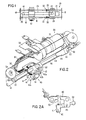
- Fig. 2 als Anwendungsbeispiel die Antriebseinheit und die Magnetkopfschlittenführung eines Sparbuchdruckers für Sparbücher mit Magnetstreifen zum Aufzeichnen und Abtasten der zu druckenden bzw. der gedruckten Informationen und
- Fig. 2A eine Detailansicht in Richtung A der Fig. 2.
- 1 is a schematic representation of the principle of action of the invention,
- Fig. 2 as an application example, the drive unit and the magnetic head carriage guide of a passbook printer for passbooks with magnetic strips for recording and scanning the information to be printed or printed and
- 2A is a detailed view in direction A of FIG. 2nd
Gemäß Fig. 1 ist ein Schlitten 10 mit einem Magnetkopf 12 auf zwei parallelen Führungsstangen 14, 16 längsverschiebbar geführt. Die Führungsstangen 14, 16 sind beiderseits mit ihren Enden in einem Rahmen 18 gelagert. Zum Antrieb des Schlittens 10 längs der Führungsstangen 14, 16, also in Richtung des Doppelpfeiles, dient eine Antriebseinheit 20, bestehend aus einem Getriebemotor 21 mit einer Antriebsscheibe 22. Zur Antriebsverbindung zwischen dem Getriebemotor 21 und dem Schlitten 10 dient ein Seil 24, das über die Antriebsscheibe 22 und eine am entgegengesetzten Ende im Rahmen 18 gelagerte Umlenkscheibe 26 geführt und mit seinen Enden am Schlitten 10 befestigt ist, so daß es eine geschlossene Schleife bildet.1, a
Der Getriebemotor 21 ist mittels eines Motorschlittens 28 gleichfalls längsverschiebbar auf den Führungsstangen 14, 16 geführt, der sich über zwei Druckfedern 30 gegen zwei Scheiben 32 abstützt, die auf den Führungsstangen 14 bzw. 16 befestigt sind. Mittels der Druckfedern 30 wird somit das Seil 24 ständig unter einer gewissen Spannung gehalten, und Längenänderungen des Seiles 24 infolge von Dehnung oder Temperaturschwankungen werden auf diese Weise selbsttätig ausgeglichen.The geared
Der Getriebemotor 21 ist umpolbar und bewirkt entsprechend den zugeführten Steuersignalen eine kontinuierliche oder schrittweise Hin- und Herbewegung des Schlittens 10 über einen vorgegebenen Weg. Hierbei im Getriebemotor 21 auftretende Schwingungen oder ähnliche Störkräfte in Richtung der Führungsstangen 14, 16 werden durch die Masse der Antriebseinheit 20 wirksam gedämpft und gelangen, soweit sie nicht bereits durch die gefederte Masse der Antriebseinheit 20 absorbiert sind, über die Druckfedern 30 auf die Führungsstangen 14, 16 und von dort unmittelbar in den Rahmen 18, ohne daß die Bewegung des Schlittens 10 davon beeinträchtigt wird. Da die Umlenkscheibe 26 starr im Rahmen 18 gelagert ist, reagiert sie nicht auf Querkräfte, die auf den Schlitten 10 wirksam werden, z. B. beim Überfahren des Magnetkopfes von Unebenheiten; infolgedessen kann auch die Umlenkscheibe 26 den Gleichlauf des Schlittenvorschubes nicht beeinträchtigen, sondern solche Querkräfte werden, soweit sie in Längskräfte über das Seil 24 umgewandelt werden, durch die Massenträgheit des Getriebemotors 21 aufgefangen.The geared
Insgesamt bildet somit der gefedert auf den Führungsstangen 14, 16 geführte Getriebemotor 21 bezüglich der längsgerichteten Schwingungen und Störkräfte ein selbständig schwingungsfähiges Feder-Masse-System, das einen sehr genauen Gleichlauf der Schlittenbewegungen gewährleistet.Overall, the geared
Bei der in Fig. 2 dargestellten Baugruppe, bestehend aus der Antriebseinheit 50 und der Magnetkopfschlittenführung eines Sparbuchdruckers, sind der Magnetkopfschlitten 40 mit dem Magnetkopf 42 und der Getriebemotor 51 mit zugehöriger Antriebsscheibe 52 auf zwei parallelen Führungsstangen 44, 46 längsverschiebbar geführt. Die Führungsstangen 44, 46 sind in seitlichen Platinen 48 des Gerätes gelagert. Der Magnetkopf 42 ist mittels Lagerstiften 42a mit Sicherungsschrauben 42b in einem Kopfträger 41 schwenkbar gelagert, der seinerseits mittels einer Achse 43 schwenkbar im Magnetkopfschlitten 40 geführt ist. Eine Feder 43a übt auf den Kopfträger 41 ein ständiges Drehmoment aus, so daß der Magnetkopf 42 beim Überfahren der Sparbuchfläche Unebenheiten, z. B. Buchkanten und -rücken, ausgleichen kann und stets mit der gleichen Kraft auf dem Magnetstreifen aufliegt. Ein Flachkabelstrang 55 verbindet den Magnetkopfschlitten 40 mit dem Magnetkopf 42 und ist gleichzeitig als Parallelführung für den schwenkbar im Kopfträger 41 geführten Magnetkopf 42 wirksam (vgl. auch Fig. 2A). Unabhängig von der jeweiligen Schwenklage des Kopfträgers 41 behält daher der Magnetkopf 42 stets seine Lage parallel zur Ebene des Magnetstreifens bei. Ein weiterer Flachkabelstrang 57 dient zur elektrischen Verbindung zwischen dem Magnetkopfschlitten 40 und einer Halterung 59 am Getriebemotor 51, von dem seinerseits entsprechende Kabelverbindungen zum Maschinengehäuse führen. Diese Kabelführung dient dazu, daß die gesamte, in Fig. 2 dargestellte Anordnung als vollständige Baueinheit austauschbar ist.In the assembly shown in FIG. 2, consisting of the
Zum Antrieb des Magnetkopfschlittens 40 längs der Führungsstangen 44, 46 ist eine Antriebseinheit 50 angeordnet, bestehend aus dem Getriebemotor 51 und dessen Antriebsscheibe 52. Über die Antriebsscheibe 52 und eine am entgegengesetzten Ende der Führungsstangen 44, 46 in der seitlichen Platine 48 gelagerte Umlenkscheibe 54 ist ein Seil 56 geführt, dessen Enden am Magnetkopfschlitten 40 befestigt sind und das somit eine geschlossene Schleife bildet. Der Getriebemotor 51 mit der Antriebsscheibe 52 ist mittels eines Motorschlittens 58 längsverschiebbar auf den Führungsstangen 44, 46 geführt und über je eine Feder 60 gegen eine C-Scheibe 62 auf den Führungsstangen 44, 46 abgestützt. Die C-Scheiben 62 sind in je einer Ringnut in den Führungsstangen 44, 46 eingesetzt und bilden daher feste Anschläge für die Federn 60. An den beiderseitigen Enden der Führungsstangen 44, 46 sind außerdem Gummipufferringe 64 aufgeschoben. Weiterhin zeigt Fig. 2 eine Rampenfläche 66, auf die im Bereich der rechten Endstellung des Magnetkopfschlittens 40 mittels einer am Kopfträger 41 angebrachten Rolle 68 der Magnetkopf 42 vom Aufzeichnungsträger abgehoben wird, so daß das eingelegte Sparbuch entnommen und ein neues eingelegt werden kann.To drive the
Die Federn 60 üben eine ständige (in Fig. 2 nach rechts gerichtete) Kraft auf den Motorschlitten 58 aus und gewährleisten die ständige Aufrechterhaltung der Spannung des Seiles 56. Außerdem werden Längenänderungen des Seiles 56 durch die Federn 60 selbsttätig ausgeglichen, ohne daß ein Nachstellen erforderlich ist.The
Die bei der Hin- und Herbewegung des Magnetkopfschlittens 40 längs der Führungsstangen 44, 46 im Getriebemotor 51 auftretenden, parallel zu diesen gerichteten Schwingungen und sonstige Störkräfte werden, wie bereits anhand von Fig. 1 beschrieben wurde, schon im Bereich ihres Entstehens, nämlich durch die federnd gelagerte Masse der Antriebseinheit 50 gedämpft und können daher nicht auf den Magnetkopfschlitten 40 übertragen werden. Die Verstellgeschwindigkeit und Positioniergenauigkeit des Magnetkopfschlittens 40 wird daher hiervon nicht beeinflußt. Die auftretenden longitudinalen Störkräfte gelangen vielmehr, soweit sie nicht ohnehin von der Federmasse der Antriebseinheit 50 und der Federn 60 absorbiert werden, als Kräfte sehr niederer Frequenz über die Führungsstangen 44, 46 und die Platinen 48 in den Rahmen des Geräts.The vibrations and other disturbing forces that occur parallel to these during the back and forth movement of the
Die von der Antriebseinheit 50 auf den Magnetkopfschlitten 40 übertragenen Bewegungen in Richtung der Führungsstangen 44, 46 laufen daher mit höchster Genauigkeit ab und bleiben von Störkräften unbeeinflußt.The movements in the direction of the
Claims (3)
characterized in that for a fixidly mounted deflecting pulley (26; 54), the drive unit (20; 50) is movable on or parallel to the guide rod and guide rods, respectively, (14, 16; 44, 46) and supported on the frame (18; 48) or a component connected thereto through a spring element (30; 60) for generating and maintaining the band tension.
Priority Applications (5)
| Application Number | Priority Date | Filing Date | Title |
|---|---|---|---|
| AT84109777T ATE34940T1 (en) | 1984-08-17 | 1984-08-17 | DRIVE DEVICE FOR A TYPE CARRIER, PRINT HEAD, MAGNETIC HEAD AND SIMILAR CARRIAGE ASSEMBLY. |
| DE8484109777T DE3471901D1 (en) | 1984-08-17 | 1984-08-17 | Drive mechanism for a carriage supporting a type carrier, print head, magnetic head or the like |
| EP84109777A EP0171454B1 (en) | 1984-08-17 | 1984-08-17 | Drive mechanism for a carriage supporting a type carrier, print head, magnetic head or the like |
| JP60104136A JPS6153074A (en) | 1984-08-17 | 1985-05-17 | Carriage drive |
| US06/766,856 US4675764A (en) | 1984-08-17 | 1985-08-16 | Drive mechanism for a magnetic head carriage assembly |
Applications Claiming Priority (1)
| Application Number | Priority Date | Filing Date | Title |
|---|---|---|---|
| EP84109777A EP0171454B1 (en) | 1984-08-17 | 1984-08-17 | Drive mechanism for a carriage supporting a type carrier, print head, magnetic head or the like |
Publications (2)
| Publication Number | Publication Date |
|---|---|
| EP0171454A1 EP0171454A1 (en) | 1986-02-19 |
| EP0171454B1 true EP0171454B1 (en) | 1988-06-08 |
Family
ID=8192117
Family Applications (1)
| Application Number | Title | Priority Date | Filing Date |
|---|---|---|---|
| EP84109777A Expired EP0171454B1 (en) | 1984-08-17 | 1984-08-17 | Drive mechanism for a carriage supporting a type carrier, print head, magnetic head or the like |
Country Status (5)
| Country | Link |
|---|---|
| US (1) | US4675764A (en) |
| EP (1) | EP0171454B1 (en) |
| JP (1) | JPS6153074A (en) |
| AT (1) | ATE34940T1 (en) |
| DE (1) | DE3471901D1 (en) |
Families Citing this family (2)
| Publication number | Priority date | Publication date | Assignee | Title |
|---|---|---|---|---|
| US4675754A (en) * | 1984-02-21 | 1987-06-23 | Mitsubishi Denki Kabushiki Kaisha | Magnetic recorder/reproducer |
| US4944616A (en) * | 1989-11-06 | 1990-07-31 | Ncr Corporation | Passbook read/write mechanism |
Family Cites Families (10)
| Publication number | Priority date | Publication date | Assignee | Title |
|---|---|---|---|---|
| US3496547A (en) * | 1965-10-12 | 1970-02-17 | American Chain & Cable Co | Control system and printer controlled thereby |
| US3572489A (en) * | 1968-11-08 | 1971-03-30 | Ibm | Typewriter with extended writing line |
| US3859662A (en) * | 1973-05-30 | 1975-01-07 | Ibm | Transducer track selection apparatus |
| US4121226A (en) * | 1977-03-25 | 1978-10-17 | Alden Research Foundation | Idler guide for facsimile scanning belt |
| DE2840052A1 (en) * | 1978-09-14 | 1980-03-27 | Agfa Gevaert Ag | RECORDING AND / OR PLAYING DEVICE FOR INFORMATION CARRIERS WITH A MAGNETIC LAYER |
| DE2905074A1 (en) * | 1979-02-10 | 1980-08-28 | Basf Ag | POSITIONING DEVICE FOR A SCAN HEAD IN A DISK INFORMATION STORAGE, IN PARTICULAR IN A MAGNETIC DISK OR FILM STORAGE |
| DE2915027C2 (en) * | 1979-04-12 | 1985-02-28 | Olympia Werke Ag, 2940 Wilhelmshaven | Device for setting a scanning device for coding disks |
| US4263632A (en) * | 1979-05-11 | 1981-04-21 | Mfe Corporation | Vibration damper for a transducer carriage drive mechanism for use in a diskette system |
| US4399477A (en) * | 1980-12-04 | 1983-08-16 | Philip Bryer | Split band actuator |
| US4395151A (en) * | 1981-11-02 | 1983-07-26 | Zenith Radio Corporation | Print head drive belt tensioning means and method for line printer |
-
1984
- 1984-08-17 DE DE8484109777T patent/DE3471901D1/en not_active Expired
- 1984-08-17 EP EP84109777A patent/EP0171454B1/en not_active Expired
- 1984-08-17 AT AT84109777T patent/ATE34940T1/en not_active IP Right Cessation
-
1985
- 1985-05-17 JP JP60104136A patent/JPS6153074A/en active Granted
- 1985-08-16 US US06/766,856 patent/US4675764A/en not_active Expired - Fee Related
Also Published As
| Publication number | Publication date |
|---|---|
| EP0171454A1 (en) | 1986-02-19 |
| JPH0423920B2 (en) | 1992-04-23 |
| US4675764A (en) | 1987-06-23 |
| DE3471901D1 (en) | 1988-07-14 |
| ATE34940T1 (en) | 1988-06-15 |
| JPS6153074A (en) | 1986-03-15 |
Similar Documents
| Publication | Publication Date | Title |
|---|---|---|
| DE69517087T2 (en) | Method and device for adjusting a printhead | |
| DE3133374C2 (en) | Print head carriage with traction means in a printing device | |
| DE3003279C2 (en) | ||
| EP0311731A1 (en) | Traction element stretching device for printers, particularly for matrix printers | |
| EP0044415A2 (en) | Oscillation mechanism for the rectilinear reciprocating movement of a matrix printer carriage | |
| EP0171454B1 (en) | Drive mechanism for a carriage supporting a type carrier, print head, magnetic head or the like | |
| DE69523685T2 (en) | Guide mechanism for printers | |
| DE1264122B (en) | Device for adjusting and guiding a stylus in a coordinate recorder | |
| DE68906994T2 (en) | Printer. | |
| DE602005002613T2 (en) | Pressure device with reciprocating carriage and two-part frame structure | |
| DE4009175C2 (en) | Lifting nozzle and button storage for sheet feeders | |
| EP0006143B1 (en) | Carriage drive for printer or teleprinter | |
| US4547089A (en) | Guide for a print head of a printing device | |
| DE3537240C2 (en) | ||
| DE2941969A1 (en) | Typewriter with sliding printing head - has extruded profile sections accommodating platen and slide guiding and fixing devices | |
| DE3322791C2 (en) | ||
| DE2929917A1 (en) | MULTICOLOR RECORDING DEVICE | |
| EP0216946B1 (en) | Matrix printer, in particular a matrix line printer | |
| EP0101071B1 (en) | Paper feeding device for printing installations | |
| DE3122645A1 (en) | Horizontal drive for a recording head | |
| DE2821173C3 (en) | High-speed printer | |
| EP0098317B1 (en) | Mounting arrangement for the oscillating frame in a matrix line printer | |
| DE2139524C3 (en) | Grapple plant | |
| DE2746674A1 (en) | DISC RECORDER WITH HEAD ADJUSTMENT | |
| DE2746914A1 (en) | DISC RECORDER WITH IMPROVED MOUNTING OF THE HEAD |
Legal Events
| Date | Code | Title | Description |
|---|---|---|---|
| PUAI | Public reference made under article 153(3) epc to a published international application that has entered the european phase |
Free format text: ORIGINAL CODE: 0009012 |
|
| AK | Designated contracting states |
Designated state(s): AT DE FR GB |
|
| 17P | Request for examination filed |
Effective date: 19860624 |
|
| 17Q | First examination report despatched |
Effective date: 19871001 |
|
| GRAA | (expected) grant |
Free format text: ORIGINAL CODE: 0009210 |
|
| AK | Designated contracting states |
Kind code of ref document: B1 Designated state(s): AT DE FR GB |
|
| REF | Corresponds to: |
Ref document number: 34940 Country of ref document: AT Date of ref document: 19880615 Kind code of ref document: T |
|
| GBT | Gb: translation of ep patent filed (gb section 77(6)(a)/1977) | ||
| REF | Corresponds to: |
Ref document number: 3471901 Country of ref document: DE Date of ref document: 19880714 |
|
| ET | Fr: translation filed | ||
| R20 | Corrections of a patent specification |
Effective date: 19880705 |
|
| PLBE | No opposition filed within time limit |
Free format text: ORIGINAL CODE: 0009261 |
|
| STAA | Information on the status of an ep patent application or granted ep patent |
Free format text: STATUS: NO OPPOSITION FILED WITHIN TIME LIMIT |
|
| 26N | No opposition filed | ||
| PGFP | Annual fee paid to national office [announced via postgrant information from national office to epo] |
Ref country code: FR Payment date: 19920724 Year of fee payment: 9 |
|
| PGFP | Annual fee paid to national office [announced via postgrant information from national office to epo] |
Ref country code: AT Payment date: 19920828 Year of fee payment: 9 |
|
| PGFP | Annual fee paid to national office [announced via postgrant information from national office to epo] |
Ref country code: GB Payment date: 19930720 Year of fee payment: 10 |
|
| PG25 | Lapsed in a contracting state [announced via postgrant information from national office to epo] |
Ref country code: AT Effective date: 19930817 |
|
| PG25 | Lapsed in a contracting state [announced via postgrant information from national office to epo] |
Ref country code: FR Effective date: 19940429 |
|
| REG | Reference to a national code |
Ref country code: FR Ref legal event code: ST |
|
| PG25 | Lapsed in a contracting state [announced via postgrant information from national office to epo] |
Ref country code: GB Effective date: 19940817 |
|
| PGFP | Annual fee paid to national office [announced via postgrant information from national office to epo] |
Ref country code: DE Payment date: 19940824 Year of fee payment: 11 |
|
| GBPC | Gb: european patent ceased through non-payment of renewal fee |
Effective date: 19940817 |
|
| PG25 | Lapsed in a contracting state [announced via postgrant information from national office to epo] |
Ref country code: DE Effective date: 19960501 |